EP1675247A2 - Elektrische Maschine mit verbesserten Verlusteigenschaften und Herstellungsverfahren hierfür - Google Patents
Elektrische Maschine mit verbesserten Verlusteigenschaften und Herstellungsverfahren hierfür Download PDFInfo
- Publication number
- EP1675247A2 EP1675247A2 EP05257855A EP05257855A EP1675247A2 EP 1675247 A2 EP1675247 A2 EP 1675247A2 EP 05257855 A EP05257855 A EP 05257855A EP 05257855 A EP05257855 A EP 05257855A EP 1675247 A2 EP1675247 A2 EP 1675247A2
- Authority
- EP
- European Patent Office
- Prior art keywords
- rotor
- section
- electrical machine
- stator
- electrical
- Prior art date
- Legal status (The legal status is an assumption and is not a legal conclusion. Google has not performed a legal analysis and makes no representation as to the accuracy of the status listed.)
- Ceased
Links
- 238000004519 manufacturing process Methods 0.000 title claims description 9
- 239000000463 material Substances 0.000 claims abstract description 33
- 238000000034 method Methods 0.000 claims description 54
- 238000004804 winding Methods 0.000 claims description 23
- 238000007747 plating Methods 0.000 claims description 17
- 239000004020 conductor Substances 0.000 claims description 14
- 239000000696 magnetic material Substances 0.000 claims description 13
- RYGMFSIKBFXOCR-UHFFFAOYSA-N Copper Chemical compound [Cu] RYGMFSIKBFXOCR-UHFFFAOYSA-N 0.000 claims description 10
- 229910052802 copper Inorganic materials 0.000 claims description 10
- 239000010949 copper Substances 0.000 claims description 10
- 238000009713 electroplating Methods 0.000 claims description 7
- PXHVJJICTQNCMI-UHFFFAOYSA-N Nickel Chemical compound [Ni] PXHVJJICTQNCMI-UHFFFAOYSA-N 0.000 claims description 6
- 239000000843 powder Substances 0.000 claims description 6
- 229910052709 silver Inorganic materials 0.000 claims description 5
- 239000004332 silver Substances 0.000 claims description 5
- 229910000831 Steel Inorganic materials 0.000 claims description 4
- 238000001513 hot isostatic pressing Methods 0.000 claims description 4
- 238000005507 spraying Methods 0.000 claims description 4
- 239000010959 steel Substances 0.000 claims description 4
- 238000007772 electroless plating Methods 0.000 claims description 3
- 229910052759 nickel Inorganic materials 0.000 claims description 3
- 239000000853 adhesive Substances 0.000 claims 1
- 230000001070 adhesive effect Effects 0.000 claims 1
- 238000003475 lamination Methods 0.000 description 8
- 238000001816 cooling Methods 0.000 description 6
- 239000002184 metal Substances 0.000 description 4
- 229910052751 metal Inorganic materials 0.000 description 4
- 230000006399 behavior Effects 0.000 description 3
- 230000004907 flux Effects 0.000 description 3
- 230000001052 transient effect Effects 0.000 description 3
- 229910000881 Cu alloy Inorganic materials 0.000 description 2
- 238000000576 coating method Methods 0.000 description 2
- 238000010438 heat treatment Methods 0.000 description 2
- 150000002739 metals Chemical class 0.000 description 2
- 239000000126 substance Substances 0.000 description 2
- 230000001360 synchronised effect Effects 0.000 description 2
- XUIMIQQOPSSXEZ-UHFFFAOYSA-N Silicon Chemical compound [Si] XUIMIQQOPSSXEZ-UHFFFAOYSA-N 0.000 description 1
- 238000005452 bending Methods 0.000 description 1
- 230000015572 biosynthetic process Effects 0.000 description 1
- 238000006243 chemical reaction Methods 0.000 description 1
- 239000011248 coating agent Substances 0.000 description 1
- 238000004590 computer program Methods 0.000 description 1
- 239000002826 coolant Substances 0.000 description 1
- 238000005260 corrosion Methods 0.000 description 1
- 230000007797 corrosion Effects 0.000 description 1
- 230000008878 coupling Effects 0.000 description 1
- 238000010168 coupling process Methods 0.000 description 1
- 238000005859 coupling reaction Methods 0.000 description 1
- 230000002500 effect on skin Effects 0.000 description 1
- 230000005611 electricity Effects 0.000 description 1
- 230000005672 electromagnetic field Effects 0.000 description 1
- 230000005284 excitation Effects 0.000 description 1
- 238000005290 field theory Methods 0.000 description 1
- 239000012530 fluid Substances 0.000 description 1
- 238000005242 forging Methods 0.000 description 1
- 238000009413 insulation Methods 0.000 description 1
- 230000004807 localization Effects 0.000 description 1
- 238000003754 machining Methods 0.000 description 1
- 238000010310 metallurgical process Methods 0.000 description 1
- 238000002360 preparation method Methods 0.000 description 1
- 229910052710 silicon Inorganic materials 0.000 description 1
- 239000010703 silicon Substances 0.000 description 1
- 239000007787 solid Substances 0.000 description 1
- 230000007704 transition Effects 0.000 description 1
Images



Classifications
-
- H—ELECTRICITY
- H02—GENERATION; CONVERSION OR DISTRIBUTION OF ELECTRIC POWER
- H02K—DYNAMO-ELECTRIC MACHINES
- H02K1/00—Details of the magnetic circuit
- H02K1/06—Details of the magnetic circuit characterised by the shape, form or construction
- H02K1/22—Rotating parts of the magnetic circuit
-
- Y—GENERAL TAGGING OF NEW TECHNOLOGICAL DEVELOPMENTS; GENERAL TAGGING OF CROSS-SECTIONAL TECHNOLOGIES SPANNING OVER SEVERAL SECTIONS OF THE IPC; TECHNICAL SUBJECTS COVERED BY FORMER USPC CROSS-REFERENCE ART COLLECTIONS [XRACs] AND DIGESTS
- Y10—TECHNICAL SUBJECTS COVERED BY FORMER USPC
- Y10T—TECHNICAL SUBJECTS COVERED BY FORMER US CLASSIFICATION
- Y10T29/00—Metal working
- Y10T29/49—Method of mechanical manufacture
- Y10T29/49002—Electrical device making
- Y10T29/49009—Dynamoelectric machine
-
- Y—GENERAL TAGGING OF NEW TECHNOLOGICAL DEVELOPMENTS; GENERAL TAGGING OF CROSS-SECTIONAL TECHNOLOGIES SPANNING OVER SEVERAL SECTIONS OF THE IPC; TECHNICAL SUBJECTS COVERED BY FORMER USPC CROSS-REFERENCE ART COLLECTIONS [XRACs] AND DIGESTS
- Y10—TECHNICAL SUBJECTS COVERED BY FORMER USPC
- Y10T—TECHNICAL SUBJECTS COVERED BY FORMER US CLASSIFICATION
- Y10T29/00—Metal working
- Y10T29/49—Method of mechanical manufacture
- Y10T29/49002—Electrical device making
- Y10T29/49009—Dynamoelectric machine
- Y10T29/49012—Rotor
Definitions
- the invention relates generally to an electrical machine, and more particularly to a rotor of an electrical machine, such as a motor and/or generator. Specifically, embodiments of the present technique provide improved loss characteristics in an electrical machine.
- an electrical machine typically includes a rotor and stator that are utilized to convert electrical power to mechanical power or vice versa.
- the stator generally includes a large number of laminations of a magnetic material that are stacked together. Within the center of the laminations, a central opening is formed throughout the length of the stator.
- the rotor may also include magnetic materials that are mounted on a shaft, which is disposed within the central opening of the stator.
- the stator may include coils or windings that form magnetic poles in the stator, while the rotor may also include windings or be a solid portion of magnetic material.
- the stator may include windings that are located adjacent to the central opening of the stator, while the rotor may include windings that are located on the outside of the rotor adjacent to the stator.
- a time-varying magnetic field is capable of producing eddy currents in electrically conductive materials, such as those from which the stator and rotor are formed.
- the magnetic metals usually exhibit a relatively high electrical resistivity. Because eddy current formation primarily depends on electrical and magnetic properties of the rotor surface, the magnetic fields produced around the rotor induce eddy currents in the rotor. These eddy currents dissipate energy via resistive heating in the rotor that increases the temperature of the rotor. As a result, eddy currents reduce the efficiency of the electrical apparatus and present thermal problems for the electrical apparatus. Further, the transient behaviors of the electrical machine are, in part, dictated by the rate at which induced eddy currents decay in the rotor surface. Thus, these eddy currents may impact the operation of the electrical machine.
- the electrical and magnetic properties of the rotor surface may be modified by attachments to address these problems.
- attachments may not be advantageous in electrical machines operating at high speeds, such as speeds exceeding 10,000 revolutions per minute because the centrifugal forces and centrifugal stress imposed on such attachments by rotation of the rotor may cause the attachments to disintegrate from the rotor.
- an electrical machine having a stator and rotor.
- the rotor is disposed within a central opening in the stator.
- the rotor includes a generally cylindrical first section comprising a first material mounted on an axially extending shaft within the central opening.
- the rotor further includes a second section having a predetermined thickness and comprising a second material plated integrally over at least a portion of the first section.
- the second material has a higher electrical conductivity relative to the first material.
- a rotor for an electrical machine is provided.
- the rotor includes a generally cylindrical first portion comprising a first material.
- the rotor further includes a second portion comprising a layer of a second material plated integrally over the first portion.
- the layer has predetermined thickness, and the second material has a higher electrical conductivity relative to the first material.
- a method for manufacturing a rotor includes fabricating a generally cylindrical first section of a rotor from a magnetic material.
- the method further includes plating a second section over at least a portion of the first section of the rotor.
- the second section comprises an electrically conductive material that is applied at a predetermined radial thickness over the first section.
- the electrically conductive material is configured to exhibit a higher electrical conductivity relative to the magnetic material.
- a method for applying a conductive layer over a rotor of an electrical machine.
- the method includes determining a thickness of the conductive layer to provide specific surface properties based on operating parameters of the electrical machine.
- the method further includes plating the conductive layer of an electrically conductive material over a surface of the rotor based on the calculated thickness, wherein the conductive layer is configured to exhibit a higher electrical conductivity than the rotor.
- the techniques discussed below involve plating of a conductive material on the metal surface of the rotor in high-speed electrical machines.
- the materials plated on the rotor surface are configured to have controlled and specified thickness and electrical conductivity. These materials improve rotor surface properties that reduce eddy current losses on the pole faces in high speed electrical machines. Certain embodiments of the present techniques are described hereinafter referring generally to FIGS. 1-5.
- the electrical machine 10 may include, for example, a motor or a generator. As illustrated, the electrical machine 10 includes a stator 12 and rotor 14 that are utilized for energy (or power) conversion.
- the stator 12 has a central opening 16 extending along the length of the stator 12 that surrounds rotor 14.
- the stator 12 generally includes multiple laminations (not shown) of at least one magnetic material that are stacked together.
- the rotor 14 comprises a generally cylindrical section 18 mounted axially on a shaft 20.
- the cylindrical section 18 of the rotor 14 is generally fabricated from a magnetic material, such as magnetic steel.
- the shaft 20 may be formed integral to the generally cylindrical section 18.
- the electrical machine 10 may be adapted for low speed or high speed operation.
- Low speed electrical machines are used, for example, as propulsion motors in electric ship drives. In the low speed operation, the rotor speeds generally do not exceed a few hundred revolutions per minute (rpm). In contrast, in high-speed electrical machines, such as those used as compact generators, the rotor speeds may exceed 10,000 rpm.
- the cylindrical magnetic section 18 of the rotor 14 may be adapted to conduct electrical current to magnetize the rotor 14, which, when subject to the time-varying AC magnetic fields produced by the stator windings, causes the rotor 14 to rotate.
- certain motor applications employ switching devices, such as thyristors or silicon-controlled rectifiers, to synthesize AC power having a desired frequency and amplitude for application to the stator 12.
- the AC power synthesized by such switches in addition to the desired fundamental frequency, also contains substantial undesired harmonics.
- harmonics represent sharp transitions of high frequencies in the current or voltage waveforms. This exposes the stator 12 and rotor 14 to variations in magnetic field at the harmonic frequencies, thereby generating eddy currents that cause excessive heat of the surface of the rotor 14.
- the eddy current losses are reduced because of the relatively thin, mutually insulated laminations of the magnetic metal.
- the thinness of each lamination, and its insulation from its neighbors, provides an extremely resistive path, thereby limiting the induced eddy currents.
- the use of such laminations is not advantageous in limiting eddy current losses in the rotor 14 because the stress imposed by rotation of the rotor at high-speed operation may cause a laminated structure to fail.
- the eddy currents produced from the non-synchronous operation in the electrical machine 10 may be a result of high frequency harmonics of stator excitation circuitry (not shown).
- the eddy currents are generally localized to the surface of the rotor 14, which is referred to as the skin effect. This localization of the eddy currents tends to confine high frequency power loss to the surface, leaving the interior of the rotor 14 relatively loss-free.
- the surface of the cylindrical section 18 of the rotor 14 is plated with a material having a high electrical conductivity relative to that of the magnetic material.
- plating the rotor 14 with a highly conductive material may reduce the amount of power dissipated by eddy currents, while not presenting the problems with machine operation.
- the electrical and magnetic properties of the rotor surface may be modified by enveloping the rotor in a high conductivity material, or by mechanically attaching higher conductivity materials to the rotor surface, such as high conductivity amortisseur (damper) bars or wedges.
- high conductivity amortisseur (damper) bars or wedges such as high conductivity amortisseur (damper) bars or wedges.
- such techniques may be undesirable in high-speed applications, as the centrifugal stress imposed on such attachments by rotation of the rotor at high speeds may cause them to disintegrate from the rotor because of the stresses involved with high speed operation. That is, the conductive coatings and mechanical attachments may not provide a bond that is strong enough to withstand the forces exerted by the high-speed operation. Unusual rotor shapes or curvatures may also make mechanical attachment difficult.
- air-cooling of the rotor 14 may not be available to reduce the heat produced by eddy currents in high -speed electrical machines.
- air-cooling of the rotor 14 causes increased air-friction on the rotor 14, which is disadvantageous for high-speed operation.
- air friction leads to increased windage losses that reduce the efficiency of the electrical machine 10.
- high-speed electrical machines are sometimes required to operate in a substantial vacuum to reduce windage losses.
- the electrical design of some machines may not allow the air gap between rotor and stator to be large enough for good air cooling. Hence, air-cooling of the rotor 14 may not be practical in such applications.
- a highly conductive material may be attached to the surface of the rotor 14 to reduce the heat and inefficiencies.
- a highly conductive material may be integrally plated onto the rotor surface because the plating leads to a stronger bond between the cylindrical section 18 and the high-conductivity layer. This stronger bond is particularly advantageous in high-speed applications wherein a high bond-strength between the cylindrical section 18 and the highly conductive layer is desirable to withstand centrifugal stresses imposed by high rotational speeds of the rotor 14.
- the conductive layer is discussed in greater detail below in FIG. 2.
- FIG. 2 illustrates a front view of the electrical machine 10 of FIG. 1 in accordance with aspects of the present techniques.
- the rotor 14 includes a conductive layer 26 of a highly conductive material disposed over the magnetic cylindrical section 18 to a predetermined thickness t 1 .
- the term conductivity should be understood to refer to electrical conductivity.
- high conductive it is meant that the conductive layer 26 is adapted to exhibit a higher degree of electrical conductivity than the cylindrical section 18.
- a highly conductive material includes copper, which exhibits high electrical conductivity, desirable corrosion resistant properties and is relatively inexpensive. Further, copper also exhibits properties of high machinability and ductility (i.e. can be subject to bending and torsion without being subject to fatigue).
- the conductive layer 26 may comprise copper alloys, including, for example combinations of copper and silver, to achieve desired plating and adhesion properties, while maintaining balanced mechanical, electrical and thermal properties.
- a bonding layer 28 may be utilized to provide improved adhesion properties thus yielding a high bond-strength. That is, the bonding layer 28 may be disposed between the magnetic cylindrical portion 18 and the conductive layer 26 to increase the strength of the adhesion of the conductive layer 26 to the magnetic cylindrical portion 18.
- the bonding layer 28 may include a layer of nickel that is plated on the surface of the cylindrical portion 18 to a predetermined thickness t 2 . Benefically, nickel provides a desired adhesion with copper, but exhibits a higher electrical resistivity (hence lower conductivity) than copper.
- the bonding layer may be applied at a certain thickness, such as thicknesses t 1 and t 2 of the conductive layer 26 and the bonding layer 28, based on calculated values that optimize the surface properties of the rotor 16.
- a certain thickness such as thicknesses t 1 and t 2 of the conductive layer 26 and the bonding layer 28, based on calculated values that optimize the surface properties of the rotor 16.
- Many such bonding layers are known in the art of plating and are usually termed "strike layers".
- the thickness t 1 of the conductive layer 26 and the thickness t 2 of the bonding layer 28 may be based on parameters calculated from electromagnetic field theory, as well as specific parameters of the particular machine.
- the design parameters may include, for example, stator winding details (for e.g. number of phases, number of coils of stator winding per phase, number of turns per coil, number of stator slots, number of winding layers, number of parallel circuits per phase, pitch ratio, etc.), various diameters (for e.g.
- the thicknesses t 1 and t 2 are computed to reduce the total rotor surface loss, while providing a desirable strength and adhesion properties. Further, the thicknesses t 1 and t 2 may depend on the nature of the process used for plating, such as electroplating, hot isostatic pressing and/or high-velocity powder spraying, which are discussed in greater detail below.
- the thicknesses t 1 and t 2 may be computed by an iterative method implemented by a computer program that accepts design parameters of the electrical machine 10, rotor 14 and/or stator 12 as inputs to arrive at optimal values of the thicknesses t1 and t2.
- FIG. 3 is a flow chart illustrating an exemplary process 30 for manufacturing a windingless rotor for an electrical machine, such as the electrical machine 10 of FIG. 1, in accordance with one embodiment of the present techniques.
- the process 30 begins at block 32.
- a generally cylindrical portion of the rotor may be fabricated from a magnetic material, such as magnetic steel. This fabrication may include forging a cylindrical shaped portion from a block of magnetic steel.
- the optimal thicknesses of the highly conductive layer and/or the bonding layer may be computed based on design parameters of the electrical machine, as described above.
- the bonding layer is applied over the surface of the cylindrical portion based on a calculated thickness of the bonding layer, as shown in block 36 following the surface preparation of the magnetic rotor 18.
- the bonding layer may not be applied over the entire cylindrical portion, but may cover a portion of the rotor.
- the conductive layer is applied over the bonding layer. Similar to the bonding layer, the conductive layer may not be applied over the entire cylindrical portion, but may cover specific portions of the cylindrical section.
- the application of the bonding and conductive layers in blocks 36 and 38 may be performed in a variety of electro-chemical and metallurgical bonding processes.
- the conductive layer may be electroplated over the surface of the cylindrical section. Electroplating is useful because it provides a smooth surface finish of the conductive layer. This smooth surface reduces windage losses in high-speed electrical machines. Further, the process of electroplating produces reduced porosity in the conductive layer 26, which results in higher electrical conductivity of the conductive layer. The electroplating process also provides control over the plating rates to enable the conductive layer to be applied to a specific thickness. Still further, the electroplating process may be configured to provide desirable adhesion properties that have a high bond-strength, which is advantageous for high-speed applications, as discussed above. These adhesion properties may also be enhanced by disposing a bonding layer between the cylindrical portion and the conductive layer.
- plating of the bonding and conductive layers over the cylindrical section may also be performed via other electrochemical or metallurgical bonding processes, such as electroless plating, hot isostatic pressing and high-velocity powder spraying, etc.
- Electroless plating is a chemical plating method not requiring electricity; hot isostatic pressing is a process which consolidates metals using high pressures and temperatures, usually starting with metallic powders; high velocity powder spraying consolidates metallic powders into a coating by throwing them against a metallic surface with a velocity high enough to partially melt them.
- the rotor may be assembled with a stator. As shown in block 40, the rotor may be assembled by axially aligning the rotor within the central opening of the stator.
- the assembly of the rotor and stator may include other steps, such as coupling other control circuits to the stator and rotor and forming the frame around the assembled rotor and stator. Thus, other assembling steps may be performed to complete the electrical machines assembly.
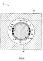
- FIG. 4 illustrates a front view of an electrical machine 42 having a stator 44 and a rotor 46 disposed inside a longitudinal opening 48 in the center of the stator 44.
- the stator 44 and rotor 46 may operate and function similar to the stator and rotor discussed above with regards to FIGs. 2 and 3.
- the rotor 46 in this embodiment may be configured to support windings.
- the rotor 46 may include a generally cylindrical portion 52, which may be made of a magnetic material.
- the cylindrical portion 52 may have longitudinal slots 54 that are machined on the surface of the cylindrical portion 52.
- the longitudinal slots 54 may be configured to support field windings 56.
- the field windings 56 when energized, create magnetic poles 58 and 60 on the surface of the rotor 46.
- the rotor 46 includes a conductive layer 66 comprising a highly conductive material plated over the pole faces 58 and 60 as well as teeth 68 of conducting region 62 and 64.
- the conductive layer 66 has specified thickness t 3 that is configured to reduce losses from eddy currents in the pole faces and the teeth 68 in the conducting regions.
- a bonding layer 70 may be disposed between the cylindrical portion 52 and the conductive layer 66 to a specified thickness t 4 to improve adhesion properties between the conductive layer 66 and the cylindrical section, as discussed above.
- the thicknesses t 3 and t 4 of the conductive layer 66 and the bonding layer 70 may be determined based on design parameters of the electrical machine 42, similar to the discussion above.
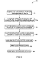
- FIG. 5 is a flow chart illustrating an exemplary process 72 for manufacturing a rotor with winding slots in accordance with another embodiment of the present techniques.
- the general manufacturing process is similar to the discussion above regarding the windingless rotor.
- the blocks 74-80 are similar in principle to blocks 32-38 of FIG. 3.
- the rotor for this process has slots machined into the rotor for the windings.
- longitudinal slots are machined on the surface of the rotor after plating the surface with a high-conductivity material. Plating is performed prior to machining of the slots to yield a uniform thickness of the high-conductivity material over the teeth and the pole faces, thus reducing windage losses at high-speed operations.
- the process 72 then proceeds at block 84 by winding coils on the slots machined on the rotor surface. Once the coils are in place, the rotor may be assembled inside the stator, as shown in block 86.
- the above-described plating techniques are also helpful in reducing losses in certain components within the stator of an electrical machine.
- An example of such a component is a stator core clamping flange.
- the present technique may be advantageous in reducing eddy currents in the stator core clamping flange surface, while providing a relatively simple mechanical structure.
- FIG 6 illustrates an exemplary electrical machine 88 in accordance with the aforementioned embodiment.
- the electrical machine 88 includes a stator member 90 having a stator core 92 formed of a plurality of laminations 94 of a magnetic material.
- the stator member 90 further includes armature windings 96 coiled around the laminated stator core 92.
- the stator core 92 is clamped on both sides (one side shown) by a core clamping flange 98.
- a rotor 100 is disposed within the stator core 92 and may include field windings 102. Certain embodiments of the rotor 100 may not include field windings as illustrated earlier.
- the rotor 100 is separated from the stator core 92 by an airgap 104.
- magnetic flux 106 from the rotor 100 may be linked to the stator core 92 and the core clamping flange 98. Due to laminations 94 in the stator core 92, flux linked to the stator core 92 does not produce significant eddy currents on the stator core 92. However, eddy currents may be formed on the surface of the core clamping flange 98, which leads to heating up of the flange 98. Traditionally, conductive shields have been used to shield the core clamping flange 98 from eddy currents caused by the flux linked to it.
- a conductive layer 108 is plated over the surface of the core clamping flange 98 via any of the electrochemical or metallurgical processes discussed above.
- the conductive layer 108 may comprise, for example copper, or copper alloys as discussed earlier.
- a bonding layer 110 may be disposed between the conducting layer 108 and the core clamping flange 98, to achieve desirable adhesion properties as discussed earlier.
- the conductive layer 108 is adapted to reduce eddy current losses in the core clamping flange 98 caused by fundamental frequency and high frequency harmonics.
- alternative cooling techniques need to be employed, such as using a hollowed flange with forced fluid cooling.
- the present techniques provide a cost effective process to control surface properties of rotors and other components in high-speed electrical machines. These techniques may reduce motor losses and optimize transient behavior for the electrical machine.
- the techniques described are particularly advantageous because they enable surface properties to be designed for reducing losses.
- the techniques provide control over the thicknesses and conductivities of the conductive layers applied to the surface of the rotor and other components.
- the present techniques improve the efficiency of the electrical machine and reduce the negative influence of transient behavior.
Landscapes
- Engineering & Computer Science (AREA)
- Power Engineering (AREA)
- Iron Core Of Rotating Electric Machines (AREA)
- Manufacture Of Motors, Generators (AREA)
Applications Claiming Priority (1)
| Application Number | Priority Date | Filing Date | Title |
|---|---|---|---|
| US11/018,592 US7723894B2 (en) | 2004-12-20 | 2004-12-20 | Electrical machine with improved loss characteristics and method of making same |
Publications (2)
| Publication Number | Publication Date |
|---|---|
| EP1675247A2 true EP1675247A2 (de) | 2006-06-28 |
| EP1675247A3 EP1675247A3 (de) | 2009-06-17 |
Family
ID=36088413
Family Applications (1)
| Application Number | Title | Priority Date | Filing Date |
|---|---|---|---|
| EP05257855A Ceased EP1675247A3 (de) | 2004-12-20 | 2005-12-20 | Elektrische Maschine mit verbesserten Verlusteigenschaften und Herstellungsverfahren hierfür |
Country Status (3)
| Country | Link |
|---|---|
| US (2) | US7723894B2 (de) |
| EP (1) | EP1675247A3 (de) |
| JP (1) | JP2006180693A (de) |
Families Citing this family (15)
| Publication number | Priority date | Publication date | Assignee | Title |
|---|---|---|---|---|
| US7723894B2 (en) * | 2004-12-20 | 2010-05-25 | General Electric Company | Electrical machine with improved loss characteristics and method of making same |
| US7705701B2 (en) * | 2005-07-15 | 2010-04-27 | General Electric Company | Thin metal layer vacuum vessels with composite structural support |
| AU2008291655B2 (en) * | 2007-08-24 | 2012-12-06 | Sunco Investments Ltd. | Multistage variable reluctance motor/generator |
| US7834509B2 (en) * | 2008-02-28 | 2010-11-16 | Hamilton Sundstrand Corporation | Rotor assembly for electromechanical machine |
| TWI448047B (zh) * | 2009-02-24 | 2014-08-01 | Sunco Invest Ltd | 多級可變磁阻電動機/發電機、其設計方法及控制邏輯與電路控制系統 |
| US20100244603A1 (en) * | 2009-03-31 | 2010-09-30 | General Electric Company | Electric machine |
| US7977845B1 (en) * | 2010-01-11 | 2011-07-12 | Heitmann Arnold M | Induction motor |
| US8350440B2 (en) * | 2010-04-14 | 2013-01-08 | General Electric Company | Integrated stator flange assembly for dynamoelectric machine |
| GB201214326D0 (en) | 2012-08-10 | 2012-09-26 | Johnson Matthey Fuel Cells Ltd | Process |
| DE102013100501A1 (de) * | 2013-01-18 | 2014-07-24 | Linde Material Handling Gmbh | Flurförderzeug mit synchroner Reluktanzmaschine |
| EP2800254A1 (de) * | 2013-04-29 | 2014-11-05 | Siemens Aktiengesellschaft | Rotor einer elektrischen Maschine mit einem ausgehend von Granulat hergestellten Kurzschlusskäfig |
| US10253649B2 (en) * | 2014-12-31 | 2019-04-09 | Ingersoll-Rand Company | Rotor construction for high speed motors |
| CN107546890B (zh) * | 2016-06-28 | 2021-07-16 | 特灵国际有限公司 | 谐波分流的电机、方法、ac电机系统及可变速驱动系统 |
| DE102016114569A1 (de) | 2016-08-05 | 2018-02-08 | Volabo Gmbh | Elektrische Maschine |
| US10826363B2 (en) * | 2018-05-10 | 2020-11-03 | Ge Aviation Systems Llc | Additively manufactured assemblies for electrical machines |
Citations (4)
| Publication number | Priority date | Publication date | Assignee | Title |
|---|---|---|---|---|
| GB601370A (en) | 1945-04-05 | 1948-05-04 | Chicago Pneumatic Tool Co | Low inertia induction motor |
| US5801470A (en) | 1996-12-19 | 1998-09-01 | General Electric Company | Rotors with retaining cylinders and reduced harmonic field effect losses |
| WO2001041287A2 (en) | 1999-12-02 | 2001-06-07 | Ispat Inland, Inc. | Asynchronous motors having simple rotor structures |
| GB2378586A (en) | 2001-07-31 | 2003-02-12 | Alstom | Rotor assembly with reduced heating due to eddy currents |
Family Cites Families (20)
| Publication number | Priority date | Publication date | Assignee | Title |
|---|---|---|---|---|
| US1659623A (en) * | 1923-12-12 | 1928-02-21 | Allis Louis Co | Dynamo-electric-machine stator |
| US2547599A (en) * | 1945-10-31 | 1951-04-03 | Casner Patents Inc | Hysteresis dynamoelectric machine |
| US3489539A (en) * | 1966-11-10 | 1970-01-13 | Gen Electric | Manganiding |
| JPS56298A (en) | 1979-06-11 | 1981-01-06 | Toshiba Corp | Plating method |
| JPS5728553A (en) * | 1980-07-28 | 1982-02-16 | Hitachi Ltd | Induction motor |
| JPH01129741A (ja) * | 1987-11-13 | 1989-05-23 | Mitsubishi Metal Corp | ローター用マグネット |
| US4843271A (en) * | 1987-12-10 | 1989-06-27 | General Electric Company | Conductive metal inserts in rotor dynamoelectric machine |
| US5118979A (en) * | 1990-12-18 | 1992-06-02 | General Electric Company | Cantilever spring contact for retaining rings on dynamoelectric machine |
| US5246565A (en) * | 1992-05-07 | 1993-09-21 | The United States Of America As Represented By The United States Department Of Energy | High adherence copper plating process |
| DE4420250C2 (de) | 1994-06-10 | 1996-12-12 | Skf Textilmasch Komponenten | Drehstrommotor, insbesondere zum Einzelantrieb einer Spinn- oder Zwirnspindel |
| DE19547682A1 (de) * | 1994-12-29 | 1996-07-04 | Gen Electric | Antikathoden-Antriebsrotor für eine Röntgenröhre |
| WO1998031497A1 (en) * | 1997-01-20 | 1998-07-23 | Kabushiki Kaisha Meidensha | Unified junction structure of rare-earth magnet and metal material and the jointing method |
| US5924967A (en) * | 1997-07-28 | 1999-07-20 | Eastman Kodak Company | Wear resistant transport roller |
| JPH11181593A (ja) * | 1997-12-16 | 1999-07-06 | Totoku Electric Co Ltd | 銅被覆アルミニウム線の製造方法 |
| CN1251381C (zh) * | 1998-04-23 | 2006-04-12 | 西铁城时计株式会社 | 小型电动机的转子 |
| JP2001028851A (ja) * | 1999-07-13 | 2001-01-30 | Nissan Motor Co Ltd | モータおよびスタータ・ジェネレータ |
| US6291919B1 (en) * | 2000-01-26 | 2001-09-18 | General Electric Company | Conductive structural interface for a non-metallic rotor enclosure |
| FR2825534B1 (fr) * | 2001-05-31 | 2003-09-05 | Valeo Equip Electr Moteur | Procede de fabrication d'un rotor de machine electrique tournante |
| JPWO2004068673A1 (ja) * | 2003-01-28 | 2006-05-25 | 本田技研工業株式会社 | 永久磁石式モータ用ロータ |
| US7723894B2 (en) * | 2004-12-20 | 2010-05-25 | General Electric Company | Electrical machine with improved loss characteristics and method of making same |
-
2004
- 2004-12-20 US US11/018,592 patent/US7723894B2/en not_active Expired - Fee Related
-
2005
- 2005-12-15 JP JP2005361170A patent/JP2006180693A/ja active Pending
- 2005-12-20 EP EP05257855A patent/EP1675247A3/de not_active Ceased
-
2010
- 2010-04-16 US US12/761,767 patent/US8671552B2/en active Active
Patent Citations (4)
| Publication number | Priority date | Publication date | Assignee | Title |
|---|---|---|---|---|
| GB601370A (en) | 1945-04-05 | 1948-05-04 | Chicago Pneumatic Tool Co | Low inertia induction motor |
| US5801470A (en) | 1996-12-19 | 1998-09-01 | General Electric Company | Rotors with retaining cylinders and reduced harmonic field effect losses |
| WO2001041287A2 (en) | 1999-12-02 | 2001-06-07 | Ispat Inland, Inc. | Asynchronous motors having simple rotor structures |
| GB2378586A (en) | 2001-07-31 | 2003-02-12 | Alstom | Rotor assembly with reduced heating due to eddy currents |
Also Published As
| Publication number | Publication date |
|---|---|
| US7723894B2 (en) | 2010-05-25 |
| US8671552B2 (en) | 2014-03-18 |
| US20100199488A1 (en) | 2010-08-12 |
| EP1675247A3 (de) | 2009-06-17 |
| JP2006180693A (ja) | 2006-07-06 |
| US20060131981A1 (en) | 2006-06-22 |
Similar Documents
| Publication | Publication Date | Title |
|---|---|---|
| US8671552B2 (en) | Method for manufacturing a rotor for an electric machine | |
| AU2017277293B2 (en) | Stator assembly with stack of coated conductors | |
| US7144468B2 (en) | Method of constructing a unitary amorphous metal component for an electric machine | |
| US5723933A (en) | Electronically commutated DC machine | |
| US6803694B2 (en) | Unitary amorphous metal component for an axial flux electric machine | |
| CA2316708C (en) | Cage-type induction motor for high rotational speeds | |
| EP0736952B1 (de) | Anker für eine Reluktanzmaschine | |
| WO2017024409A1 (en) | Electric machine | |
| US9985502B2 (en) | Reducing high frequency losses in an electric machine | |
| EP3567701B1 (de) | Magnetmodul für eine dauermagnetmaschine | |
| WO1996042132A1 (en) | High speed synchronous reluctance motor-generator | |
| EP3748813B1 (de) | Permanentmagnetmodul für eine permanentmagnetmaschine | |
| Powell et al. | Rotor topologies for a switched-reluctance machine for the ‘more-electric’aircraft engine | |
| CN112054605B (zh) | 用于永磁电机的永磁体模块 | |
| Zhu et al. | Design of Litz Wire for a Slotless High-speed Permanent Magnet Motor with Gramme-ring Windings | |
| GB2378586A (en) | Rotor assembly with reduced heating due to eddy currents | |
| CN112740519A (zh) | 用于制造旋转电机的绕组头装置的方法 | |
| CN210536357U (zh) | 用于永磁电机的永磁体模块、永磁电机和风力涡轮机 | |
| EP4040645A1 (de) | Verlustarmer dämpferstab für elektrische maschinen | |
| Abdelli et al. | Design and Manufacturing of Axial Flux Permanent Magnet Machines for Electric Vehicle Applications | |
| Gerada et al. | Optimal split ratio for high speed induction machines | |
| JP2004222410A (ja) | モータのステータ鉄心 | |
| JPH11206045A (ja) | 回転電機 | |
| Benarous et al. | A brushless disc drive using powder iron stator | |
| HK1092954B (en) | Method of constructing a unitary amorphous metal component for an electric machine |
Legal Events
| Date | Code | Title | Description |
|---|---|---|---|
| PUAI | Public reference made under article 153(3) epc to a published international application that has entered the european phase |
Free format text: ORIGINAL CODE: 0009012 |
|
| AK | Designated contracting states |
Kind code of ref document: A2 Designated state(s): AT BE BG CH CY CZ DE DK EE ES FI FR GB GR HU IE IS IT LI LT LU LV MC NL PL PT RO SE SI SK TR |
|
| AX | Request for extension of the european patent |
Extension state: AL BA HR MK YU |
|
| PUAL | Search report despatched |
Free format text: ORIGINAL CODE: 0009013 |
|
| AK | Designated contracting states |
Kind code of ref document: A3 Designated state(s): AT BE BG CH CY CZ DE DK EE ES FI FR GB GR HU IE IS IT LI LT LU LV MC NL PL PT RO SE SI SK TR |
|
| AX | Request for extension of the european patent |
Extension state: AL BA HR MK YU |
|
| 17P | Request for examination filed |
Effective date: 20091217 |
|
| 17Q | First examination report despatched |
Effective date: 20100119 |
|
| AKX | Designation fees paid |
Designated state(s): DE FR GB IT |
|
| STAA | Information on the status of an ep patent application or granted ep patent |
Free format text: STATUS: THE APPLICATION HAS BEEN REFUSED |
|
| 18R | Application refused |
Effective date: 20130426 |