EP1675754B1 - Socle porteur de charge - Google Patents
Socle porteur de charge Download PDFInfo
- Publication number
- EP1675754B1 EP1675754B1 EP04775533A EP04775533A EP1675754B1 EP 1675754 B1 EP1675754 B1 EP 1675754B1 EP 04775533 A EP04775533 A EP 04775533A EP 04775533 A EP04775533 A EP 04775533A EP 1675754 B1 EP1675754 B1 EP 1675754B1
- Authority
- EP
- European Patent Office
- Prior art keywords
- base part
- cavity
- load carrier
- locking device
- walls
- Prior art date
- Legal status (The legal status is an assumption and is not a legal conclusion. Google has not performed a legal analysis and makes no representation as to the accuracy of the status listed.)
- Expired - Lifetime
Links
Images


Classifications
-
- B—PERFORMING OPERATIONS; TRANSPORTING
- B60—VEHICLES IN GENERAL
- B60R—VEHICLES, VEHICLE FITTINGS, OR VEHICLE PARTS, NOT OTHERWISE PROVIDED FOR
- B60R9/00—Supplementary fittings on vehicle exterior for carrying loads, e.g. luggage, sports gear or the like
- B60R9/04—Carriers associated with vehicle roof
- B60R9/045—Carriers being adjustable or transformable, e.g. expansible, collapsible
Definitions
- the present invention relates to a load carrier foot for connecting a load carrier bar to an elongated rail profile of a vehicle, having in the longitudinal direction of the rail an extending cavity, with an upwards turned opening, in which the width of the cavity across the longitudinal direction of the rail exceeding the width of the opening, whereby the cavity on each side of the opening having walls, which facing the bottom of the cavity, wherein the load carrier foot having a base part, which extends through the opening towards the bottom of the cavity and comprising a fastening device which by means of a clamping device is moved upwards to clamping connection with the walls when the base part being secured to the rail profile.
- Load carrier feet of the above-described kind are previously known.
- the disadvantage with these previously known load carrier feet is however that the locking device may ends up in an incorrect position when being fastened against the walls, whereby an unsafe connection of the load carrier foot to the rail profile is created.
- the locking device When the locking device is located within the cavity it may not be established if the device lands in incorrect position. It may neither be actuated from the outside, why the user may not for certain establish if a safe connection of the load carrier foot to the rail profile comes about.
- US 2001/0013 528 describes a load carrier foot according to the preamble of claim 1.
- a load carrier foot which is designed in such way that the locking device always ends up in a position in which the tightening device is tightened against the walls and which may be actuated in position from the outside of the rail profile, and is connected with an indication device, which may be observed from the outside of the rail profile and which disclose in which position the locking device is within the rail profile.
- the present invention overcomes the mentioned disadvantages with a load carrier foot of the introductory stated kind, which is characterized in that a connection means is firmly connected with the locking device and rotatable connected to the base part, and in that an elastic body is located between the base part and the connection means, which turns the connection means and the locking device to a position in which the locking device being located transverse relative the longitudinal direction of the rail profile when the base part is mounted to the cavity, and in which position the locking device certainly will be in contact with the walls when the locking device by the clamping device being clamped against the walls.
- connection means having an arm of control, which is placed on the side of the base part that is located on the outside of the cavity of the rail profile.
- the present invention is characterized by that the controlling arm being located in an indication position, where the locking device by the elastic body has been moved to the position in which it safely will be in engagement with the walls, when being tightened by the tightening device.
- the present invention is characterized in that the elastic device consists of a torsion spring.
- connection means with the controlling arm may be twisted against the force from the elastic body, from the position of indication to a second position in which the locking device extends in essential same direction as the base part.
- a vehicle 1 being shown with elongated rail profiles 3 connected to the roof 2, and to which load carrier rods 4 provided with load carrier feet 5 according to the present invention are mounted.
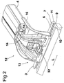
- Figure 2 discloses a part of a rail profile 3, which longitudinal direction has been indicated with the double arrow L and to which a load carrier foot 5 is mounted.
- the rail profile has a cavity 6, with an upwards-turned opening 7, and in figure 3 the width of the cavity being indicated with B and the width of the opening with b. As appear from the figure the width of the cavities being larger than the width of the opening.
- the cover 8 which covers the inner part of the foot and which being shown in figure 1, and the only function of which is to provide an attractive exterior, is omitted in the figure.
- the bottom of the cavity 6 being indicated with 9 and the walls of the cavity, located adjacent to the opening, being indicated with 10 and 11 respectively, and as appear these are facing the bottom 9 of the cavity.
- the load carrier foot comprises a frame part 12 and a base part 13.
- the frame part is in an upper end 14, in known manner, connected to the load carrier bar 4 with bolts 15, of which only one being shown in the figure.
- the base part 13 is mounted to the rail profile in a known way, as will appear from below.
- a cover 16 appear in the figure, which is located on the inside and which extends between the base part and load carrier bar, and the function of which is, in the same manner as the cover 8, to make a attractive exterior.
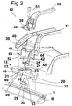
- FIG 3 is an explosion view of the load carrier foot shown in figure 2, but with the load carrier bar 4 omitted.
- the base part 13 which comprises a flat part 17, which centrally having a block 18.
- Support shoulders 19, 20 are arranged on the underside of the part 17, which have a respective abutting surface 21, 22, whose function will be explained below.
- a cylindrical hole 23 extends through the block 18, in which an elastic body in form of a torsion spring 24 together with a cylinder 25 are mounted in a manner as will appear below.
- an opening 26 is formed which extends into the hole 23.
- the opening is defined by a first end surface 27 and a second end surface 28, which surfaces clearly being shown in figure 5.
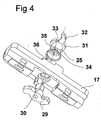
- a fastening device 29 being shown, which is firmly connected to a shaft 30, having a non-circularly cross section. The shaft is connected to the cylinder 25 in a way as will appear from the description below.
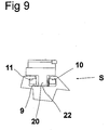
- the base part and fastening device is viewed from below. From the figure appear that the cylinder 25 in its upper area having a flange 31 to which an arm 32 is connected and a notch 33 is formed in the flange 31. In the cylinder is further a recess 34 arranged, having a non-circularly cross section. From the figures the torsion spring 24 also appears, which have a first connecting pin 35 and a second connecting pin 36.
- the frame part 12 comprise a first bracket part 37 and a second bracket part 38, of which the second part is firmly connected to the first part, when the frame part is mounted to the base part.
- the connection of the second part to the first part may happen by welding, riveting, soldering or on every other suitable way.
- a first tab 39 through which is formed a hole 40, a second tab 41 and a third tab 42, which having a respective hatch 43, 44.
- the torsion spring 24 is mounted to the cylinder 25 and the first connecting pin 35 is mounted in the notch 33.
- the cylinder with the torsion spring is moved into the through hole 23 and the second connecting pin 36 is mounted to a notch 45, formed in the circumferential surface of the hole 23.
- the cylinder is moved downwards so far into the hole 23, that the arm 32, will be in contact with the bottom surface 46 of the opening 26.
- the second and the third tab are mounted into the recesses 47 and 48, respectively, formed in the plate 17, and in connection to that the first tab 39 is located over the cylinder 25, whereby ensuring that the cylinder being held on place in the hole 23.
- the tabs 41 and 42, respectively, are connected firmly to the recesses 47 and 48, respectively, through that the hatches 43 and 44 will be in engagement with the knobs 49 and 50, respectively, arranged in the recesses 47 and 48, see figure 5.
- the shaft 30 is located on the fastening device 29 in the opening 34, and a bolt 51 is moved through the hole 40 and a hole 52, formed in the shaft 25, to connection with a threaded hole 53 in the shaft, whereby the locking device over the shaft and the cylinder become turnable connected to the base part and with the bolt 51 tightly connected to the base part.
- the function of the base part should hereafter be described.
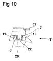
- the arm 32 being turned against the force of the torsion spring to the position it has in figure 6.
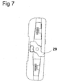
- the locking device occupies the position that is shown in figure 8.
- the longitudinal direction of the locking device being indicated with the double arrow R and the longitudinal direction of the base part being indicated with the double arrow N.
- the direction L and N are parallel, and in the position that is shown in figure 8, the locking device thus extends in a parallel direction to the rail profile, and the base part may thus be mounted to the rail profile.
- the arm 32 is located in a certain position, which is viewable from the outside of the rail profile, and in this position also the locking device is in a position in which it will be in engagement with the walls. If the arm should be located in the position shown in figure 6, the user will know that the locking device is misplaced and by moving the arm to the position shown in figure 2 assuring oneself that the locking device is in correct position.
- the arm 32 functioning as an indicating organ and in the indicating position, shown in figure 2 and 5, indicating that the locking device have the correct position, while in other positions the locking device is misplaced and may be dealt with by moving the arm 32 to the correct position.
Landscapes
- Engineering & Computer Science (AREA)
- Mechanical Engineering (AREA)
- Fittings On The Vehicle Exterior For Carrying Loads, And Devices For Holding Or Mounting Articles (AREA)
- Vehicle Step Arrangements And Article Storage (AREA)
- Socks And Pantyhose (AREA)
- Finger-Pressure Massage (AREA)
- Medicines Containing Material From Animals Or Micro-Organisms (AREA)
Claims (5)
- Pied de porte-charge (5) destiné à relier une barre de porte-charge (4) à un profil en rail allongé (3) d'un véhicule (1) présentant, dans la direction longitudinale (L) du rail, une cavité allongée (6), avec une ouverture orientée vers le haut (7), dans lequel la largeur (B) de la cavité transversalement à la direction longitudinale du rail excède la largeur (b) de l'ouverture, de telle sorte que la cavité sur chaque côté de l'ouverture comporte des parois (10, 11), qui sont orientées face au fond (9) de la cavité, de telle sorte que le pied de porte-charge comporte une partie de base (13), qui s'étend à travers l'ouverture vers le fond de la cavité, et comprenant un dispositif de fixation (29) qui, au moyen d'un dispositif de blocage (51) est déplacé vers le haut en contact de blocage avec les parois lorsque la partie de base est fixée sur le profil en rail, caractérisé en ce qu'un moyen de liaison (25, 30) est relié fermement au dispositif de verrouillage (29) et relié de manière à pouvoir tourner à la partie de base (13), et en ce qu'un corps élastique (24) est situé entre la partie de base et le moyen de liaison, ce qui fait tourner le moyen de liaison et le dispositif de verrouillage vers une position dans laquelle le dispositif de verrouillage est positionné transversalement par rapport à la direction longitudinale (figure 7) du profil en rail lorsque la partie de base est montée dans la cavité, et dans laquelle position, le dispositif de verrouillage est, de manière certaine, en contact avec les parois (10, 11) lorsque le dispositif de verrouillage, par le dispositif de blocage (51), est bloqué contre les parois.
- Pied de porte-charge selon la revendication 1, caractérisé en ce que le moyen de liaison (25, 30) comporte un bras de commande (32) qui est situé sur le côté de la partie de base qui est située à l'extérieur de la cavité des profils en rail.
- Pied de porte-charge selon la revendication 2, caractérisé en ce que le bras de commande (32) est placé dans une position indicatrice (figure 2) lorsque le dispositif de verrouillage (29) est déplacé par le corps élastique (24) vers la position dans laquelle il est couplé de manière certaine avec les parois, lorsqu'il est bloqué par le dispositif de blocage.
- Pied de porte-charge selon l'une quelconque des revendications précédentes, caractérisé en ce que le dispositif élastique consiste en un ressort de torsion (24).
- Pied de porte-charge selon l'une quelconque des revendications précédentes, caractérisé en ce que le moyen de liaison (25, 30) avec le bras de commande (32) peut être tordu contre l'action du corps élastique (24), à partir de la position d'indication vers une seconde position (figure 8) dans laquelle le dispositif de verrouillage s'étend sensiblement dans la même direction que la partie de base, dans lequel la partie de base peut être introduite dans l'ouverture du profil en rail et ressortie de celle-ci.
Applications Claiming Priority (2)
| Application Number | Priority Date | Filing Date | Title |
|---|---|---|---|
| SE0302690A SE0302690L (sv) | 2003-10-13 | 2003-10-13 | Lastbärarfot |
| PCT/SE2004/001452 WO2005035315A1 (fr) | 2003-10-13 | 2004-10-12 | Socle porteur de charge |
Publications (2)
| Publication Number | Publication Date |
|---|---|
| EP1675754A1 EP1675754A1 (fr) | 2006-07-05 |
| EP1675754B1 true EP1675754B1 (fr) | 2008-01-09 |
Family
ID=29398710
Family Applications (1)
| Application Number | Title | Priority Date | Filing Date |
|---|---|---|---|
| EP04775533A Expired - Lifetime EP1675754B1 (fr) | 2003-10-13 | 2004-10-12 | Socle porteur de charge |
Country Status (6)
| Country | Link |
|---|---|
| US (1) | US20060208022A1 (fr) |
| EP (1) | EP1675754B1 (fr) |
| AT (1) | ATE383278T1 (fr) |
| DE (1) | DE602004011249D1 (fr) |
| SE (1) | SE0302690L (fr) |
| WO (1) | WO2005035315A1 (fr) |
Families Citing this family (15)
| Publication number | Priority date | Publication date | Assignee | Title |
|---|---|---|---|---|
| US20060273123A1 (en) * | 2004-09-27 | 2006-12-07 | Settelmayer Joseph J | Rack tower assemblies and rack systems |
| US20060237500A1 (en) * | 2004-12-13 | 2006-10-26 | Settelmayer Joseph J | Side rail rack with removable base |
| NZ561809A (en) | 2007-09-21 | 2009-11-27 | Hubco Automotive Ltd | Resilient infill |
| NZ561811A (en) | 2007-09-21 | 2010-06-25 | Hubco Automotive Ltd | Extendable roof rack |
| NZ561860A (en) * | 2007-09-24 | 2010-04-30 | Hubco Automotive Ltd | Versatile leg for a roof rack |
| NZ571287A (en) * | 2008-09-15 | 2011-03-31 | Hubco Automotive Ltd | A bracket and a crossbar assembly for a roof rack |
| US8499988B2 (en) * | 2011-09-21 | 2013-08-06 | Ford Global Technologies, Llc | Roof rack crossbar |
| AU2013255540A1 (en) * | 2012-04-30 | 2014-12-18 | Yakima Australia Pty Limited | Retention dock |
| WO2014022435A1 (fr) | 2012-07-30 | 2014-02-06 | Yakima Innovation Development Corporation | Élément de remplissage de barre transversale à fentes en t |
| EP3013647B1 (fr) | 2013-06-24 | 2018-05-23 | Mont Blanc Industri AB | Pied de support pour porte-bagages |
| US10040403B2 (en) | 2015-06-09 | 2018-08-07 | Yakima Products, Inc. | Crossbar clamp actuator |
| IT202200019269A1 (it) * | 2022-09-20 | 2024-03-20 | Fb Design Srl | Sistema modulare di riconfigurazione del layout di una imbarcazione. |
| IT202300019155A1 (it) * | 2023-09-18 | 2025-03-18 | Fb Design Srl | Sistema modulare di riconfigurazione del layout di una imbarcazione. |
| US12559040B2 (en) * | 2024-04-07 | 2026-02-24 | Jason Huang | High strength adjustable automotive cross bar cargo carrier |
| USD1046753S1 (en) * | 2024-05-08 | 2024-10-15 | Zhijun He | Vehicle cross bar |
Family Cites Families (8)
| Publication number | Priority date | Publication date | Assignee | Title |
|---|---|---|---|---|
| US4106680A (en) * | 1976-05-05 | 1978-08-15 | Bott John Anthony | Vehicle article carrier |
| US5593265A (en) * | 1995-08-16 | 1997-01-14 | Chrysler Corporation | Quick-connect stored energy torsional fastener |
| GB2330614B (en) * | 1997-07-25 | 2001-10-03 | Baker Martin Aircraft Co | Fittings for securing seating and other equipment in aircraft |
| SE9900324D0 (sv) * | 1999-01-29 | 1999-01-29 | Thule Ind Ab | Takräckesanordning vid motorfordon |
| US6305589B1 (en) * | 1999-03-01 | 2001-10-23 | Industri Ab Thule | Vertically engageable carrier foot |
| US6739487B2 (en) * | 1999-03-01 | 2004-05-25 | Thule Sweden Ab | Vertically engageable carrier foot |
| US6415970B1 (en) * | 2000-10-20 | 2002-07-09 | Jac Products, Inc. | Vehicle article carrier with supports configurable elevated siderails or flush mounted slats |
| US7044345B2 (en) * | 2002-02-25 | 2006-05-16 | Jac Products, Inc. | Single sided releaseable article carrier using leaf spring |
-
2003
- 2003-10-13 SE SE0302690A patent/SE0302690L/sv unknown
-
2004
- 2004-10-12 AT AT04775533T patent/ATE383278T1/de not_active IP Right Cessation
- 2004-10-12 EP EP04775533A patent/EP1675754B1/fr not_active Expired - Lifetime
- 2004-10-12 WO PCT/SE2004/001452 patent/WO2005035315A1/fr not_active Ceased
- 2004-10-12 DE DE602004011249T patent/DE602004011249D1/de not_active Expired - Lifetime
-
2006
- 2006-04-13 US US11/279,727 patent/US20060208022A1/en not_active Abandoned
Also Published As
| Publication number | Publication date |
|---|---|
| DE602004011249D1 (de) | 2008-02-21 |
| US20060208022A1 (en) | 2006-09-21 |
| SE0302690D0 (sv) | 2003-10-13 |
| SE525573C2 (sv) | 2005-03-15 |
| ATE383278T1 (de) | 2008-01-15 |
| EP1675754A1 (fr) | 2006-07-05 |
| WO2005035315A1 (fr) | 2005-04-21 |
| SE0302690L (sv) | 2005-03-15 |
Similar Documents
| Publication | Publication Date | Title |
|---|---|---|
| EP1675754B1 (fr) | Socle porteur de charge | |
| EP0044952B1 (fr) | Poignée de porte pour véhicule automobile | |
| CA2403229A1 (fr) | Dispositif de verrouillage de la direction a bouton-poussoir | |
| KR20010059692A (ko) | 모듈러 클립 | |
| PL343157A1 (en) | Flat composite body, especially a motor vehicle body element | |
| GB2341914B (en) | Vehicle steering column assembly | |
| JP4834560B2 (ja) | ヒュージブルリンクの取付構造 | |
| EP1715233B1 (fr) | Plaque de raccordement entre une vanne et un organe d'actionnement | |
| US11254285B2 (en) | Apparatus for preventing forcible separation of shift cable | |
| KR980008865A (ko) | 가스 백 모듈 | |
| US7681284B1 (en) | Hinge | |
| JPS5841204B2 (ja) | 車輛用滑止め具 | |
| JPH06276649A (ja) | フロアコンセント | |
| KR100535133B1 (ko) | 스타터 제어 장치 | |
| EP2949553B1 (fr) | Pédale transformable en élément antivol | |
| JPS63184544A (ja) | バツクアツププレ−トの取付構造 | |
| JP3276508B2 (ja) | ステアリングホイール | |
| KR200347364Y1 (ko) | 프레임 연결구조 | |
| EP1103431B1 (fr) | Dispositif de positionnement et de fixation d'un module de coussin gonflable | |
| JPH0715062Y2 (ja) | カットアウトの取付構造 | |
| EP1367198B1 (fr) | Serrure | |
| JP2001102043A (ja) | バッテリーへの電線接続構造 | |
| JP2553812Y2 (ja) | ミラーブラケツト | |
| US7229097B2 (en) | Snap-in capsule for steering columns | |
| KR200144193Y1 (ko) | 자동차 트렁크의 키이실린더 취부구조 |
Legal Events
| Date | Code | Title | Description |
|---|---|---|---|
| PUAI | Public reference made under article 153(3) epc to a published international application that has entered the european phase |
Free format text: ORIGINAL CODE: 0009012 |
|
| 17P | Request for examination filed |
Effective date: 20060427 |
|
| AK | Designated contracting states |
Kind code of ref document: A1 Designated state(s): AT BE BG CH CY CZ DE DK EE ES FI FR GB GR HU IE IT LI LU MC NL PL PT RO SE SI SK TR |
|
| DAX | Request for extension of the european patent (deleted) | ||
| 17Q | First examination report despatched |
Effective date: 20070202 |
|
| RIN1 | Information on inventor provided before grant (corrected) |
Inventor name: KARLSSON, PETER |
|
| GRAP | Despatch of communication of intention to grant a patent |
Free format text: ORIGINAL CODE: EPIDOSNIGR1 |
|
| GRAS | Grant fee paid |
Free format text: ORIGINAL CODE: EPIDOSNIGR3 |
|
| GRAA | (expected) grant |
Free format text: ORIGINAL CODE: 0009210 |
|
| AK | Designated contracting states |
Kind code of ref document: B1 Designated state(s): AT BE BG CH CY CZ DE DK EE ES FI FR GB GR HU IE IT LI LU MC NL PL PT RO SE SI SK TR |
|
| REG | Reference to a national code |
Ref country code: GB Ref legal event code: FG4D |
|
| REG | Reference to a national code |
Ref country code: CH Ref legal event code: EP |
|
| REG | Reference to a national code |
Ref country code: IE Ref legal event code: FG4D |
|
| REF | Corresponds to: |
Ref document number: 602004011249 Country of ref document: DE Date of ref document: 20080221 Kind code of ref document: P |
|
| PG25 | Lapsed in a contracting state [announced via postgrant information from national office to epo] |
Ref country code: SI Free format text: LAPSE BECAUSE OF FAILURE TO SUBMIT A TRANSLATION OF THE DESCRIPTION OR TO PAY THE FEE WITHIN THE PRESCRIBED TIME-LIMIT Effective date: 20080109 Ref country code: NL Free format text: LAPSE BECAUSE OF FAILURE TO SUBMIT A TRANSLATION OF THE DESCRIPTION OR TO PAY THE FEE WITHIN THE PRESCRIBED TIME-LIMIT Effective date: 20080109 |
|
| NLV1 | Nl: lapsed or annulled due to failure to fulfill the requirements of art. 29p and 29m of the patents act | ||
| PG25 | Lapsed in a contracting state [announced via postgrant information from national office to epo] |
Ref country code: LI Free format text: LAPSE BECAUSE OF FAILURE TO SUBMIT A TRANSLATION OF THE DESCRIPTION OR TO PAY THE FEE WITHIN THE PRESCRIBED TIME-LIMIT Effective date: 20080109 Ref country code: CH Free format text: LAPSE BECAUSE OF FAILURE TO SUBMIT A TRANSLATION OF THE DESCRIPTION OR TO PAY THE FEE WITHIN THE PRESCRIBED TIME-LIMIT Effective date: 20080109 Ref country code: ES Free format text: LAPSE BECAUSE OF FAILURE TO SUBMIT A TRANSLATION OF THE DESCRIPTION OR TO PAY THE FEE WITHIN THE PRESCRIBED TIME-LIMIT Effective date: 20080420 Ref country code: FI Free format text: LAPSE BECAUSE OF FAILURE TO SUBMIT A TRANSLATION OF THE DESCRIPTION OR TO PAY THE FEE WITHIN THE PRESCRIBED TIME-LIMIT Effective date: 20080109 |
|
| REG | Reference to a national code |
Ref country code: CH Ref legal event code: PL |
|
| PG25 | Lapsed in a contracting state [announced via postgrant information from national office to epo] |
Ref country code: AT Free format text: LAPSE BECAUSE OF FAILURE TO SUBMIT A TRANSLATION OF THE DESCRIPTION OR TO PAY THE FEE WITHIN THE PRESCRIBED TIME-LIMIT Effective date: 20080109 Ref country code: BG Free format text: LAPSE BECAUSE OF FAILURE TO SUBMIT A TRANSLATION OF THE DESCRIPTION OR TO PAY THE FEE WITHIN THE PRESCRIBED TIME-LIMIT Effective date: 20080409 |
|
| PG25 | Lapsed in a contracting state [announced via postgrant information from national office to epo] |
Ref country code: PL Free format text: LAPSE BECAUSE OF FAILURE TO SUBMIT A TRANSLATION OF THE DESCRIPTION OR TO PAY THE FEE WITHIN THE PRESCRIBED TIME-LIMIT Effective date: 20080109 Ref country code: BE Free format text: LAPSE BECAUSE OF FAILURE TO SUBMIT A TRANSLATION OF THE DESCRIPTION OR TO PAY THE FEE WITHIN THE PRESCRIBED TIME-LIMIT Effective date: 20080109 Ref country code: PT Free format text: LAPSE BECAUSE OF FAILURE TO SUBMIT A TRANSLATION OF THE DESCRIPTION OR TO PAY THE FEE WITHIN THE PRESCRIBED TIME-LIMIT Effective date: 20080609 |
|
| EN | Fr: translation not filed | ||
| PG25 | Lapsed in a contracting state [announced via postgrant information from national office to epo] |
Ref country code: DK Free format text: LAPSE BECAUSE OF FAILURE TO SUBMIT A TRANSLATION OF THE DESCRIPTION OR TO PAY THE FEE WITHIN THE PRESCRIBED TIME-LIMIT Effective date: 20080109 Ref country code: CZ Free format text: LAPSE BECAUSE OF FAILURE TO SUBMIT A TRANSLATION OF THE DESCRIPTION OR TO PAY THE FEE WITHIN THE PRESCRIBED TIME-LIMIT Effective date: 20080109 Ref country code: SE Free format text: LAPSE BECAUSE OF FAILURE TO SUBMIT A TRANSLATION OF THE DESCRIPTION OR TO PAY THE FEE WITHIN THE PRESCRIBED TIME-LIMIT Effective date: 20080409 Ref country code: SK Free format text: LAPSE BECAUSE OF FAILURE TO SUBMIT A TRANSLATION OF THE DESCRIPTION OR TO PAY THE FEE WITHIN THE PRESCRIBED TIME-LIMIT Effective date: 20080109 |
|
| PLBE | No opposition filed within time limit |
Free format text: ORIGINAL CODE: 0009261 |
|
| STAA | Information on the status of an ep patent application or granted ep patent |
Free format text: STATUS: NO OPPOSITION FILED WITHIN TIME LIMIT |
|
| PG25 | Lapsed in a contracting state [announced via postgrant information from national office to epo] |
Ref country code: RO Free format text: LAPSE BECAUSE OF FAILURE TO SUBMIT A TRANSLATION OF THE DESCRIPTION OR TO PAY THE FEE WITHIN THE PRESCRIBED TIME-LIMIT Effective date: 20080109 |
|
| 26N | No opposition filed |
Effective date: 20081010 |
|
| PG25 | Lapsed in a contracting state [announced via postgrant information from national office to epo] |
Ref country code: DE Free format text: LAPSE BECAUSE OF FAILURE TO SUBMIT A TRANSLATION OF THE DESCRIPTION OR TO PAY THE FEE WITHIN THE PRESCRIBED TIME-LIMIT Effective date: 20080410 |
|
| PG25 | Lapsed in a contracting state [announced via postgrant information from national office to epo] |
Ref country code: FR Free format text: LAPSE BECAUSE OF FAILURE TO SUBMIT A TRANSLATION OF THE DESCRIPTION OR TO PAY THE FEE WITHIN THE PRESCRIBED TIME-LIMIT Effective date: 20081031 Ref country code: EE Free format text: LAPSE BECAUSE OF FAILURE TO SUBMIT A TRANSLATION OF THE DESCRIPTION OR TO PAY THE FEE WITHIN THE PRESCRIBED TIME-LIMIT Effective date: 20080109 |
|
| PG25 | Lapsed in a contracting state [announced via postgrant information from national office to epo] |
Ref country code: MC Free format text: LAPSE BECAUSE OF NON-PAYMENT OF DUE FEES Effective date: 20081031 |
|
| PG25 | Lapsed in a contracting state [announced via postgrant information from national office to epo] |
Ref country code: CY Free format text: LAPSE BECAUSE OF FAILURE TO SUBMIT A TRANSLATION OF THE DESCRIPTION OR TO PAY THE FEE WITHIN THE PRESCRIBED TIME-LIMIT Effective date: 20080109 |
|
| PG25 | Lapsed in a contracting state [announced via postgrant information from national office to epo] |
Ref country code: IT Free format text: LAPSE BECAUSE OF FAILURE TO SUBMIT A TRANSLATION OF THE DESCRIPTION OR TO PAY THE FEE WITHIN THE PRESCRIBED TIME-LIMIT Effective date: 20080109 |
|
| PG25 | Lapsed in a contracting state [announced via postgrant information from national office to epo] |
Ref country code: IE Free format text: LAPSE BECAUSE OF NON-PAYMENT OF DUE FEES Effective date: 20081013 |
|
| PGFP | Annual fee paid to national office [announced via postgrant information from national office to epo] |
Ref country code: GB Payment date: 20091022 Year of fee payment: 6 |
|
| PG25 | Lapsed in a contracting state [announced via postgrant information from national office to epo] |
Ref country code: HU Free format text: LAPSE BECAUSE OF FAILURE TO SUBMIT A TRANSLATION OF THE DESCRIPTION OR TO PAY THE FEE WITHIN THE PRESCRIBED TIME-LIMIT Effective date: 20080710 Ref country code: LU Free format text: LAPSE BECAUSE OF NON-PAYMENT OF DUE FEES Effective date: 20081012 |
|
| PG25 | Lapsed in a contracting state [announced via postgrant information from national office to epo] |
Ref country code: TR Free format text: LAPSE BECAUSE OF FAILURE TO SUBMIT A TRANSLATION OF THE DESCRIPTION OR TO PAY THE FEE WITHIN THE PRESCRIBED TIME-LIMIT Effective date: 20080109 |
|
| PG25 | Lapsed in a contracting state [announced via postgrant information from national office to epo] |
Ref country code: GR Free format text: LAPSE BECAUSE OF FAILURE TO SUBMIT A TRANSLATION OF THE DESCRIPTION OR TO PAY THE FEE WITHIN THE PRESCRIBED TIME-LIMIT Effective date: 20080410 |
|
| GBPC | Gb: european patent ceased through non-payment of renewal fee |
Effective date: 20101012 |
|
| PG25 | Lapsed in a contracting state [announced via postgrant information from national office to epo] |
Ref country code: GB Free format text: LAPSE BECAUSE OF NON-PAYMENT OF DUE FEES Effective date: 20101012 |
|
| P01 | Opt-out of the competence of the unified patent court (upc) registered |
Effective date: 20230528 |