EP1676128B1 - Verfahren und vorrichtung zur prüfung eines eine komplexe oberflächenkontur aufweisenden bauteils mittels ultraschall - Google Patents
Verfahren und vorrichtung zur prüfung eines eine komplexe oberflächenkontur aufweisenden bauteils mittels ultraschall Download PDFInfo
- Publication number
- EP1676128B1 EP1676128B1 EP04790247A EP04790247A EP1676128B1 EP 1676128 B1 EP1676128 B1 EP 1676128B1 EP 04790247 A EP04790247 A EP 04790247A EP 04790247 A EP04790247 A EP 04790247A EP 1676128 B1 EP1676128 B1 EP 1676128B1
- Authority
- EP
- European Patent Office
- Prior art keywords
- trigger
- surface contour
- along
- axis
- axial drives
- Prior art date
- Legal status (The legal status is an assumption and is not a legal conclusion. Google has not performed a legal analysis and makes no representation as to the accuracy of the status listed.)
- Expired - Lifetime
Links
- 238000002604 ultrasonography Methods 0.000 title claims abstract description 29
- 238000000034 method Methods 0.000 title claims abstract description 22
- 238000012360 testing method Methods 0.000 title claims description 17
- 239000000523 sample Substances 0.000 claims description 16
- 230000001360 synchronised effect Effects 0.000 claims description 11
- 238000005259 measurement Methods 0.000 claims description 6
- 238000010998 test method Methods 0.000 claims 1
- 238000001514 detection method Methods 0.000 description 5
- 238000009825 accumulation Methods 0.000 description 1
- 238000010276 construction Methods 0.000 description 1
- 238000010586 diagram Methods 0.000 description 1
- 230000006870 function Effects 0.000 description 1
- 230000003287 optical effect Effects 0.000 description 1
- 238000000053 physical method Methods 0.000 description 1
Images


Classifications
-
- G—PHYSICS
- G01—MEASURING; TESTING
- G01N—INVESTIGATING OR ANALYSING MATERIALS BY DETERMINING THEIR CHEMICAL OR PHYSICAL PROPERTIES
- G01N29/00—Investigating or analysing materials by the use of ultrasonic, sonic or infrasonic waves; Visualisation of the interior of objects by transmitting ultrasonic or sonic waves through the object
- G01N29/22—Details, e.g. general constructional or apparatus details
- G01N29/26—Arrangements for orientation or scanning by relative movement of the head and the sensor
- G01N29/265—Arrangements for orientation or scanning by relative movement of the head and the sensor by moving the sensor relative to a stationary material
-
- G—PHYSICS
- G01—MEASURING; TESTING
- G01N—INVESTIGATING OR ANALYSING MATERIALS BY DETERMINING THEIR CHEMICAL OR PHYSICAL PROPERTIES
- G01N29/00—Investigating or analysing materials by the use of ultrasonic, sonic or infrasonic waves; Visualisation of the interior of objects by transmitting ultrasonic or sonic waves through the object
- G01N29/04—Analysing solids
- G01N29/06—Visualisation of the interior, e.g. acoustic microscopy
- G01N29/0609—Display arrangements, e.g. colour displays
- G01N29/0645—Display representation or displayed parameters, e.g. A-, B- or C-Scan
-
- G—PHYSICS
- G01—MEASURING; TESTING
- G01N—INVESTIGATING OR ANALYSING MATERIALS BY DETERMINING THEIR CHEMICAL OR PHYSICAL PROPERTIES
- G01N29/00—Investigating or analysing materials by the use of ultrasonic, sonic or infrasonic waves; Visualisation of the interior of objects by transmitting ultrasonic or sonic waves through the object
- G01N29/22—Details, e.g. general constructional or apparatus details
- G01N29/225—Supports, positioning or alignment in moving situation
-
- G—PHYSICS
- G01—MEASURING; TESTING
- G01N—INVESTIGATING OR ANALYSING MATERIALS BY DETERMINING THEIR CHEMICAL OR PHYSICAL PROPERTIES
- G01N2291/00—Indexing codes associated with group G01N29/00
- G01N2291/02—Indexing codes associated with the analysed material
- G01N2291/028—Material parameters
- G01N2291/02854—Length, thickness
-
- G—PHYSICS
- G01—MEASURING; TESTING
- G01N—INVESTIGATING OR ANALYSING MATERIALS BY DETERMINING THEIR CHEMICAL OR PHYSICAL PROPERTIES
- G01N2291/00—Indexing codes associated with group G01N29/00
- G01N2291/10—Number of transducers
- G01N2291/101—Number of transducers one transducer
-
- G—PHYSICS
- G01—MEASURING; TESTING
- G01N—INVESTIGATING OR ANALYSING MATERIALS BY DETERMINING THEIR CHEMICAL OR PHYSICAL PROPERTIES
- G01N2291/00—Indexing codes associated with group G01N29/00
- G01N2291/26—Scanned objects
- G01N2291/263—Surfaces
- G01N2291/2638—Complex surfaces
Definitions
- the invention relates to a method for testing a complex surface contour having a component by means of ultrasound, wherein at least one Ultraschallprüfkopf by means of a multi-axis actuators manipulator is guided in a plurality of axes with a defined distance along the surface contour of the component and wherein according to the movement of at least one drive equidistant Pulses are generated as trigger signals for the geometrically correct assignment of received ultrasound measured values to the surface contour of the component, and to a device for testing a component having a complex surface contour, comprising a manipulator which can be moved in one or more axes by means of axle drives, with which at least one ultrasound test head with a defined distance along the surface contour of the component is movable, wherein the axle drives are controlled by a controller and wherein at least one encoder to produce is provided by trigger pulses for the geometrically correct assignment of received ultrasonic measurements to the surface contour of the component.
- a method for testing a complex surface contour having a component by means of ultrasound wherein on a conventional multi-axis sketchmanipulator one or more ultrasonic sensors are arranged, which are moved along a straight or slightly curved surface contour of a component for testing this , At least one axle drive of the manipulator is equipped to generate trigger pulses for an ultrasound control unit, preferably with an optical encoder.
- This encoder is assigned to a main axis such as X-axis.
- the encoder generates according to the movement of the associated final drive Equidistant pulses for a motion vector of the connected axis.
- the equidistant impulses are necessary as a trigger for the geometrically correct assignment of the ultrasonic measured values to the test part.
- a device 10 with single-axis trigger system is in Fig. 1 shown.
- the device 10 comprises a multi-axis manipulator 12, wherein each axis such as X-axis, Y-axis, Z-axis and possibly rotary axes such as A-axis or B-axis is assigned a respective drive MX, MY, MZ, MA, MB which can be controlled via corresponding control cards SX, SY, SZ, SA, SB via an NC controller NCS.
- One of the axle drives in the example shown the drive MX of the X-axis, is coupled to an encoder E, which emits equidistant pulses to an ultrasound system USS in accordance with the movement of the associated final drive.
- the trigger pulses are generated proportional to the feed of the linear X-axis.
- the ultrasound system USS is coupled to a control computer SR, which in turn is connected to the NC controller of the multiple manipulator.
- surface-accurate data acquisition means that an equidistant measuring point grid on the surface of the component is made available for the later presentation of the measurement results as a fixed C-image.
- the calibration method described aims to provide a new calibration method which is independent of the construction of a sensor unit and accordingly requires no prior physical measurement of geometrical parameters.
- the knowledge of the geometric parameters of the sensor unit is replaced by that of an easily dimensioned calibration object.
- the establishment of an intermediate transfer function takes place directly by detecting the raw information under the same conditions as the later measurement of the points of an object, so that an error accumulation can be avoided.
- the EP-A-0 489 161 refers to an ultrasonic crack detector. Distance sensors and an ultrasonic probe are connected together as a unitary structure so that the distance sensor is passed over the scan lines along with the ultrasonic probe. The surface scanning of an object W by means of the distance sensor is performed in parallel with the crack detection by the ultrasonic probe.
- the crack detection area is divided into a plurality of smaller areas, and a plurality of memory areas similar to a network are stored in a memory. Only one area value of the location storage area includes the crack detection area and is stored in each of the storage areas. Based on these stored shape data, the position and angle of the ultrasonic probe in each of the crack detection points can be controlled.
- the invention is based on the problem of further developing a method and a device of the aforementioned type such that a high measuring accuracy is ensured even for components having a complexly curved surface contour.
- the problem will u. a. procedurally achieved in that the length of the surface contour reproducing surface line is calculated that support points are calculated to guide the Ultraschallprüfkopfes that the axle drives of the manipulator along the precalculated support points are synchronously moved and that a trigger drive synchronized with the axis drives and driven together with all meshing axis drives is moved according to the precalculated surface line, wherein the trigger drive of the surface line is fictitiously stirred and generated with respect to the surface line equidistant trigger pulses.
- the basic idea of the method is, with the aid of a web synchronously to be traversed additional motor or drive with a connected encoder for the generation of Trigger pulses to ensure a true-to-scale measurement value assignment even for components with complex curved surface contours.
- a prediction of a surface line is calculated in accordance with a geometry of the component to be tested which is entered manually or taken over from CAD data.
- the calculation is preferably carried out in a control computer of the ultrasound system.
- points of the multi-axis manipulator for guiding the ultrasonic probe system at a defined distance along the surface contour of the component in the control computer of the ultrasound system are calculated. In this case, for example, a meandering measuring travel is performed over the surface contour of the component.
- the synchronized method of the multiple drive axes of the multi-axis manipulator in space along the precalculated and the NC control transferred bases of the additional motor as a so-called trigger drive or space trigger (virtual axis) synchronized by the NC control together with all others in Traversing axis drives proceed according to the pre-calculated surface line.
- the synchronized method of the actual movement axes for the exact guidance of the ultrasound probe system at a defined distance along the surface contour of the component and the space trigger axis ensures that the space trigger axis fictitiously tracks the surface line and thus outputs equidistant pulses via the connected encoder to the ultrasound system.
- a trigger drive for generating the trigger pulses is provided that the trigger drive synchronized with the axis drives of the manipulator is controlled, the axis drives are moved synchronously along precalculated support points and the trigger drive is synchronized by the controller together with the axle drives according to a predicted length of a surface contour reproducing surface line is movable and that on the encoder (E) Trigger pulses are applied to the trigger drive, which are equidistant with respect to the surface line of the complex surface contour.
- another axis or a trigger drive is defined, i. H. a motor connected to the NC control, which synchronizes in the synchronized process of the axis drives of the multi-axis manipulator in the space along vorausbepiter bases and is moved by the NC control together with all other engaging axes corresponding to the precalculated surface line, so that is guaranteed in that the trigger drive fictitiously tracks the surface line and thus supplies equidistant pulses to the ultrasound system via the connected encoder.
- Fig. 1 shows an assembly 10 for testing a surface contour OK having a component BT by means of a single-axis trigger system, which has already been described in detail in the introduction to the description.
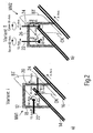
- the multi-axis manipulator MM1 comprises a substantially U-shaped frame 12, which can be moved on the bottom side along guide rails 14, 16 along a first axis such as X-axis by means of a drive MX.
- the U-shaped frame substantially encloses the component BT to be tested.
- the holding elements 22, 24 along an even further axis such as Z-axis, in the direction of the component to be tested BT to and away from the movable. Furthermore, a rotation of the ultrasound Prütkopfsystems UPS about a longitudinal axis such as A-axis of the holding element 22, 24 is possible.
- FIG. 2b shown multi-axis manipulator MM2 differs from that in Fig. 2 a manipulator MM1 shown by the fact that the holding elements 22, 24 are not arranged on the vertically extending legs 18, 20 of the frame 12, but along a Y-axis of an upper, horizontally extending cross member 26 are movable. Furthermore, the holding elements 22, 24 along a vertically extending Z-axis movable.
- the ultrasound probe system UPS is also arranged pivotable about an A-axis.
- the holding elements 22, 24 are rotatable about their longitudinal axis, in the present case about a B-axis.
- Fig. 3 shows an assembly 28 for testing a complex surface contour OK having component BT by means of ultrasound.
- the arrangement comprises the multi-axis manipulator MM for guiding the ultrasound probe system UPS at a defined distance A along the surface contour OK of the component BT.
- the multi-axis manipulator MM comprises the drives MX, MY, MZ, MA, MB for driving the individual axes such as X-axis, Y-axis, Z-axis, A-axis and B-axis, which are controlled via control cards SX, SY, SZ, SA, SB are coupled to the controller NCS.
- a further drive or motor MRT is provided which is connected via a control card SRT to the controller NCS.
- the motor MRT is coupled to an encoder E, which provides trigger signals to an ultrasound system USS, which is connected to a control computer SR, which in turn is connected to the control of the multi-axis manipulator NCS.
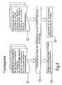
- Fig. 4 shows a flowchart of the method.
- a surface line OL in particular its length, is calculated in accordance with the geometry of the component to be tested BT, which is entered manually or taken from CAD data (section S2). This is followed by a precalculation of bases of the multi-axis manipulator MM for guiding the ultrasound probe system UPS at a defined distance A (section S1). This calculation also takes place in the control computer SR of the ultrasound system.
- a meandering measuring travel is performed over the surface contour OK of the component BT.
- the space-locked motor MRT which can be considered a virtual axis, is synchronized by the NC controller NCS together with the other axes which are engaged the pre-calculated surface line OL (section S3).
Landscapes
- Physics & Mathematics (AREA)
- General Health & Medical Sciences (AREA)
- Immunology (AREA)
- Chemical & Material Sciences (AREA)
- Analytical Chemistry (AREA)
- Biochemistry (AREA)
- Health & Medical Sciences (AREA)
- General Physics & Mathematics (AREA)
- Life Sciences & Earth Sciences (AREA)
- Pathology (AREA)
- Acoustics & Sound (AREA)
- Investigating Or Analyzing Materials By The Use Of Ultrasonic Waves (AREA)
- Ultra Sonic Daignosis Equipment (AREA)
- Manipulator (AREA)
- Length Measuring Devices Characterised By Use Of Acoustic Means (AREA)
Description
- Die Erfindung bezieht sich auf ein Verfahren zur Prüfung eines eine komplexe Oberflächenkontur aufweisenden Bauteils mittels Ultraschall, wobei zumindest ein Ultraschallprüfkopf mittels eines mehrere Achsantriebe aufweisenden Manipulators in mehreren Achsen mit definiertem Abstand entlang der Oberflächenkontur des Bauteils geführt wird und wobei entsprechend der Bewegung zumindest eines Antriebs äquidistante Impulse als Triggersignale zur geometrisch korrekten Zuordnung von empfangenen Ultraschallmesswerten zur Oberflächenkontur des Bauteils erzeugt werden, sowie auf eine Vorrichtung zur Prüfung eines eine komplexe Oberflächenkontur aufweisenden Bauteils, umfassend einen mittels Achsantrieben in einen oder mehreren Achsen verfahrbaren Manipulator, mit dem zumindest ein Ultraschallprüfkopf mit definiertem Abstand entlang der Oberflächenkontur des Bauteils verfahrbar ist, wobei die Achsantriebe mittels einer Steuerung ansteuerbar sind und wobei zumindest ein Encoder zur Erzeugung von Triggerimpulsen zur geometrisch korrekten Zuordnung von empfangenen Ultraschallmesswerten zur Oberflächenkontur des Bauteils vorgesehen ist.
- Aus einem internen Stand der Technik ist ein Verfahren zur Prüfung eines eine komplexe Oberflächenkontur aufweisenden Bauteils mittels Ultraschall bekannt, wobei an einem herkömmlichen Mehrachsen-Prüfmanipulator ein oder mehrere Ultraschallgeber angeordnet sind, welche entlang einer geraden oder leicht gekrümmten Oberflächenkontur eines Bauteils zur Prüfung dieses verfahren werden. Zumindest ein Achsantrieb des Manipulators ist zur Erzeugung von Triggerimpulsen für eine Ultraschallsteuereinheit mit vorzugsweise einem optischen Encoder ausgestattet. Dieser Encoder ist jeweils einer Hauptachse wie X-Achse zugeordnet. Bei einer automatisierten Prüfung des Bauteils erzeugt der Encoder entsprechend der Bewegung des zugehörigen Achsantriebes äquidistante Impulse für einen Bewegungsvektor der angeschlossenen Achse. Die äquidistanten Impulse sind als Trigger zur geometrisch korrekten Zuordnung der Ultraschallmesswerte zum Prüfteil notwendig.
- Eine Vorrichtung 10 mit Einachsen-Triggersystem nach diesem Stand der Technik ist in
Fig. 1 dargestellt. Die Vorrichtung 10 umfasst einen Mehrachsenmanipulator 12, wobei jeder Achse wie beispielsweise X-Achse, Y-Achse, Z-Achse sowie ggf. Drehachsen wie A-Achse oder B-Achse jeweils ein Antrieb MX, MY, MZ, MA, MB zugeordnet ist, welche über entsprechende Steuerkarten SX, SY, SZ, SA, SB über eine NC-Steuerung NCS ansteuerbar sind. Einer der Achsantriebe, im dargestellten Beispiel der Antrieb MX der X-Achse, ist mit einem Encoder E gekoppelt, welcher entsprechend der Bewegung des zugehörigen Achsantriebes äquidistante Impulse an ein Ultraschallsystem USS abgibt. Dabei werden die Triggerimpulse proportional dem Vorschub der linearen X-Achse erzeugt. Das Ultraschallsystem USS ist mit einem Steuerrechner SR gekoppelt, welcher wiederum mit der NC-Steuerung des Mehrfachmanipulators verbunden ist. - Wenn die Geometrie der Oberflächenkontur des zu prüfenden Bauteils in Haupt-Prüfrichtung komplex gekrümmt ist, kann mit einer Einachsen-Triggererzeugung keine ausreichende Genauigkeit der oberflächengetreuen Datenaufnahme gewährleistet werden. Oberflächengetreue Datenaufnahme bedeutet in diesem Sinne, dass ein äquidistantes Messpunktgitter auf der Oberfläche des Bauteils für die spätere Darstellung der Messergebnisse als fixiertes C-Bild zur Verfügung gestellt wird.
- In der
DE-T- 690 03 090 wird ein Kalibrierungsverfahren eines dreidimensionalen Formerfassungssystems und ein System zur Durchführung des genannten Verfahrens beschrieben. Das beschriebene Kalibrierungsverfahren zielt darauf ab, ein neues Eichverfahren zu schaffen, welches von dem Aufbau einer Sensoreinheit unabhängig ist und dementsprechend keine vorherige physische Messung von geometrischen Parametern erfordert. Bei dem Verfahren wird die Kenntnis der geometrischen Parameter der Sensoreinheit durch die eines einfach zu bemaßenden Kalibrierobjektes ersetzt. Die Aufstellung einer Zwischentransferfunktion erfolgt direkt durch eine Erfassung der Rohinformation unter denselben Bedingungen, wie die spätere Messung der Punkte eines Objektes, so dass dadurch eine Fehlerhäufung vermieden werden kann. - Die
EP-A- 0 489 161 bezieht sich auf einen Ultraschall-Riss-Detektor. Abstandssensoren und ein Ultraschalltastkopf sind miteinander als eine einheitliche Struktur verbunden, so dass der Abstandssensor zusammen mit dem Ultraschallprüfkopf über die Scannlinien geführt wird. Die Oberflächenabtastung eines Objektes W mittels des Abstandssensors erfolgt parallel mit der Risserfassung durch den Ultraschallprüfkopf. Der Risserfassungsbereich ist in eine Vielzahl kleinerer Bereiche unterteilt, wobei eine Vielzahl von Speicherbereichen ähnlich eines Netzes in einem Speicher abgelegt werden. Nur ein Flächenwert des Positionsspeicherbereiches enthält den Risserfassungsbereich und ist in jedem der Speicherbereiche gespeichert. Basierend auf diesen gespeicherten Formdaten kann die Position und der Winkel bzw. Lage des Ultraschallprüflcopfes in jedem der Rissdetektionspunkte gesteuert werden. - Davon ausgehend liegt der Erfindung das Problem zu Grunde, ein Verfahren und eine Vorrichtung der zuvor genannten Art dahingehend weiterzuentwickeln, dass auch bei Bauteilen mit komplex gekrümmter Oberflächenkontur eine hohe Messgenauigkeit gewährleistet ist.
- Das Problem wird u. a. verfahrensmäßig dadurch gelöst, dass die Länge einer die Oberflächenkontur wiedergebende Oberflächenlinie berechnet wird, dass Stützpunkte zur Führung des Ultraschallprüfkopfes berechnet werden, dass die Achsantriebe des Manipulators entlang der vorausberechneten Stützpunkte synchron verfahren werden und dass ein Trigger-Antrieb synchronisiert mit den Achsantrieben angesteuert und zusammen mit allen im Eingriff befindlichen Achsantrieben entsprechend der vorausberechneten Oberflächenlinie verfahren wird, wobei der Trigger-Antrieb der Oberflächenlinie fiktiv nachgerührt wird und bezogen auf die Oberflächenlinie äquidistante Triggerimpulse generiert.
- Grundgedanke des Verfahrens ist es, mit Hilfe eines bahnsynchron zu verfahrenden zusätzlichen Motors bzw. Antriebs mit angeschlossenem Encoder zur Erzeugung von Triggerimpulsen eine oberflächengetreue Messwertzuordnung auch bei Bauteilen mit komplex gekrümmten Oberflächenkonturen zu gewährleisten.
- Hierbei ist vorgesehen, dass eine Vorausberechnung einer Oberflächenlinie, insbesondere deren Länge entsprechend einer manuell eingegebenen oder aus CAD-Daten übernommenen Geometrie des zu prüfenden Bauteils berechnet wird. Die Berechnung wird vorzugsweise in einem Steuerrechner des Ultraschallsystems durchgeführt. Ferner werden Stützpunkte des Mehrachsen-Manipulators zur Führung des Ultraschall-Prüfkopfsystems in definiertem Abstand entlang der Oberflächenkontur des Bauteils im Steuerrechner des Ultraschallsystems berechnet. Dabei wird beispielsweise eine mäanderförmige Messfahrt über die Oberflächenkontur des Bauteils durchgeführt.
- Anschließend wird beim synchronisierten Verfahren der mehreren Antriebsachsen des Mehrachsen-Manipulators im Raum entlang der vorausberechneten und der NC-Steuerung übergebenen Stützpunkte der zusätzliche Motor als sogenannter Trigger-Antrieb bzw. Raumtrigger (virtuelle Achse) synchronisiert von der NC-Steuerung zusammen mit allen anderen im Eingriff befindlichen Achsantrieben entsprechend der vorausberechneten Oberflächenlinie verfahren. Durch das synchronisierte Verfahren der eigentlichen Bewegungsachsen zur exakten Führung des Ultraschall-Prüfkopfsystems in definiertem Abstand entlang der Oberflächenkontur des Bauteils und der Raumtriggerachse ist gewährleistet, dass die Raumtriggerachse die Oberflächenlinie fiktiv nachführt und somit äquidistante Impulse über den angeschlossenen Encoder an das Ultraschallsystem ausgibt.
- Das Problem wird durch eine Vorrichtung dadurch gelöst, dass zusätzlich zu den Achsantrieben ein Trigger-Antrieb zur Erzeugung der Triggerimpulse vorgesehen ist, dass der Trigger-Antrieb synchronisiert mit den Achsantrieben des Manipulators ansteuerbar ist, wobei die Achsantriebe entlang von vorausberechneten Stützpunkten synchron verfahrbar sind und der Trigger-Antrieb synchronisiert von der Steuerung zusammen mit den Achsantrieben entsprechend einer vorausberechneten Länge einer die Oberflächenkontur wiedergebenden Oberflächenlinie verfahrbar ist und dass an dem Encoder (E) des Trigger-Antriebs Triggerimpulse anliegen, die bezogen auf die Oberflächenlinie der komplexen Oberflächenkontur äquidistant sind.
- Zusätzlich zu den vorhandenen Achsantrieben des Mehrachsen-Manipulators wird eine weitere Achse bzw. ein Trigger-Antrieb definiert, d. h. ein an die NC-Steuerung angeschlossener Motor, welcher beim synchronisierten Verfahren der Achsantriebe des Mehrachsen-Manipulators im Raum entlang vorausberechneter Stützpunkte synchronisiert und von der NC-Steuerung zusammen mit allen anderen im Eingriff befindlichen Achsen entsprechend der vorausberechneten Oberflächenlinie verfahren wird, so dass gewährleistet ist, dass der Trigger-Antrieb die Oberflächenlinie fiktiv nachführt und somit äquidistante Impulse über den angeschlossenen Encoder an das Ultraschallsystem liefert.
- Weitere Einzelheiten, Vorteile und Merkmale der Erfindung ergeben sich nicht nur aus den Ansprüchen, den diesen zu entnehmenden Merkmalen - für sich und/oder in Kombination -, sondern auch aus der nachfolgenden Beschreibung von der Zeichnung zu entnehmenden bevorzugten Ausführungsbeispielen.
- Es zeigen:
- Fig. 1
- eine Anordnung zur Prüfung eines Bauteils mittels Ultraschall mit Einachsen-Triggersystem nach dem Stand der Technik,
- Fig. 2 a, b
- Prinzipdarstellungen eines Manipulatorsystems,
- Fig. 3
- eine Anordnung zur Prüfung eines Bauteils mittels Ultraschall mit Raumgitter-Triggersystem und
- Fig. 4
- ein Flussdiagramm mit Ablaufschritten zur Durchführung des Verfahrens zur Prüfung eines eine komplexe Oberflächenkontur aufweisenden Bauteils mittels Ultraschall.
-
Fig. 1 zeigt eine Anordnung 10 zur Prüfung eines eine Oberflächenkontur OK aufweisenden Bauteils BT mittels eines Einachsen-Triggersystems, welches in der Beschreibungseinleitung bereits ausführlich beschrieben wurde. - Die
Fig. 2a ) und b) zeigen zwei Ausführungsformen des Mehrachsen-Manipulators MM zur Führung eines Ultraschall-Prüfkopfsystems UPS in definiertem Abstand A entlang der Oberflächenkontur OK des Bauteils BK. Gemäß einer ersten Ausführungsform umfasst der Mehrachsen-Manipulator MM1 ein im Wesentlichen U-förmiges Gestell 12, welches bodenseitig entlang von Führungsschienen 14, 16 entlang einer ersten Achse wie X-Achse mittels eines Antriebs MX verfahrbar ist. Dabei umschließt das U-förmige Gestell beim Verfahren in X-Richtung im Wesentlichen das zu prüfende Bauteil BT. An vertikal verlaufenden Schenkeln 18, 20 des Gestells 12 sind entlang einer weiteren Achse wie Y-Achse verfahrbare Halteelemente 22, 24 angebracht, an denen das Ultraschall-Prüfkopfsystem UPS befestigt ist. Ferner sind die Halteelemente 22, 24 entlang einer noch weiteren Achse wie Z-Achse, in Richtung auf das zu prüfende Bauteil BT zu und von diesem weg bewegbar. Ferner ist eine Rotation des Ultraschall-Prütkopfsystems UPS um eine Längsachse wie A-Achse des Halteelementes 22, 24 möglich. - Ein in
Fig. 2b dargestellter Mehrachsen-Manipulator MM2 unterscheidet sich von dem inFig. 2 a dargestellten Manipulator MM1 dadurch, dass die Halteelemente 22, 24 nicht an den vertikal verlaufenden Schenkeln 18, 20 des Gestells 12 angeordnet sind, sondern entlang einer Y-Achse eines oberen, horizontal verlaufenden Querträgers 26 verfahrbar sind. Ferner sind die Halteelemente 22, 24 entlang einer vertikal verlaufenden Z-Achse verfahrbar. Das Ultraschall-Prüfkopfsystem UPS ist zudem um eine A-Achse schwenkbar angeordnet. Optional ist vorgesehen, dass die Halteelemente 22, 24 um ihre Längsachse, im vorliegenden Fall um eine B-Achse, drehbar sind. -
Fig. 3 zeigt eine Anordnung 28 zur Prüfung eines eine komplexe Oberflächenkontur OK aufweisenden Bauteils BT mittels Ultraschall. Die Anordnung umfasst den Mehrachsen-Manipulator MM zur Führung des Ultraschall-Prüfkopfsystems UPS in definiertem Abstand A entlang der Oberflächenkontur OK des Bauteils BT. Der Mehrachsen-Manipulator MM umfasst die Antriebe MX, MY, MZ, MA, MB zum Antrieb der einzelnen Achsen wie X-Achse, Y-Achse, Z-Achse, A-Achse und B-Achse, welche über Steuerkarten SX, SY, SZ, SA, SB mit der Steuerung NCS gekoppelt sind. Gemäß der Erfindung ist ein weiterer Antrieb bzw. Motor MRT vorgesehen, der über eine Steuerkarte SRT mit der Steuerung NCS verbunden ist. Der Motor MRT ist mit einem Encoder E gekoppelt, der Triggersignale an ein Ultraschallsystem USS liefert, welches mit einem Steuerrechner SR verbunden ist, der wiederum mit der Steuerung des Mehrachsen-Manipulators NCS verbunden ist. -
Fig. 4 zeigt ein Flussdiagramm des Verfahrens. In dem Steuerrechner für das Ultraschallsystem SR werden eine Oberflächenlinie OL, insbesondere deren Länge entsprechend von manuell eingegebenen oder aus CAD-Daten übernommenen Geometrie des zu prüfenden Bauteils BT berechnet (Schnitt S2). Anschließend erfolgt eine Vorausberechnung von Stützpunkten des Mehrachsen-Manipulators MM zur Führung des Ultraschall-Prüfkopfsystems UPS in definiertem Abstand A (Schnitt S1). Diese Berechnung erfolgt ebenfalls im Steuerrechner SR des Ultraschall-Systems. - Vorzugsweise wird eine mäanderförmige Messfahrt über die Oberflächenkontur OK des Bauteils BT durchgeführt. Beim synchronen Verfahren der Achsen im Raum entlang der voraus berechneten und der Steuerung NCS übergebenen Stützpunkte wird der Raumtriggennotor MRT, der als virtuelle Achse angesehen werden kann, synchronisiert von der NC-Steuerung NCS zusammen mit den anderen Achsen, welche sich im Eingriff befinden, entsprechend der vorausberechneten Oberflächenlinie OL verfahren (Schnitt S3). Durch das synchronisierte Verfahren der eigentlichen Bewegungsachsen, d. h. der X-, Y-, Z-, A- und B-Achsen zur exakten Führung des Ultraschall-Prüfkopfsystems UPS in definiertem Abstand A entlang der Oberfläche OK sowie durch Verfahren der Raumtriggerachse des Raumtriggermotors MRT ist gewährleistet, dass die Raumtriggerachse fiktiv die Oberflächenlinie OL nachführt (Schnitt S4) und somit äquidistante Impulse TI über den angeschlossenen Encoder E an das Ultraschallsystem USS abgegeben werden (Schnitt S5).
- Dadurch wird eine ausreichende Genauigkeit der oberflächengetreuen Datenaufnahme, d. h. ein äquidistantes Messpunktgitter an der Oberfläche des Bauteils für die spätere Darstellung der Messergebnisse als pixeliertes C-Bild gewährleistet.
Claims (6)
- Verfahren zur Prüfung eines eine komplexe Oberflächenkontur (OK) aufweisenden Bauteils (BT) mittels Ultraschall, wobei zumindest ein Ultraschallprüfkopf (UPK) mittels eines mehrere Achsantriebe (MX, MJ, MZ, MA, MB) aufweisenden Manipulators (MM) in mehreren Achsen mit definiertem Abstand (A) entlang der Oberflächenkontur (OK) des Bauteils (BT) geführt wird und wobei entsprechend der Bewegung zumindest eines Antriebs äquidistante Impulse als Triggersignale zur geometrisch korrekten Zuordnung von empfangenen Ultraschallmesswerten zur Oberflächenkontur (OK) des Bauteils erzeugt werden,
dadurch gekennzeichnet,
dass die Länge einer die Oberflächenkontur (OK) wiedergebende Oberflächenlinie (OL) berechnet wird,
dass Stützpunkte zur Führung des Ultraschallprüfkopfes (UPK) berechnet werden,
dass die Achsantriebe (MX, MJ, MZ, MA, MB) des Manipulators (MM) entlang der vorausberechneten Stützpunkte synchron verfahren werden und
dass ein Trigger-Antrieb (MRT) synchronisiert mit den Achsantrieben (MX, MJ, MZ, MA, MB) angesteuert und zusammen mit allen im Eingriff befindlichen Achsantrieben entsprechend der vorausberechneten Oberflächenlinie (OL) verfahren wird, wobei der Trigger-Antrieb (MRT) der Oberflächenlinie (OL) fiktiv nachgeführt wird und bezogen auf die Oberflächenlinie (OL) äquidistante Triggerimpulse generiert. - Verfahren nach Anspruch 1,
dadurch gekennzeichnet,
dass die Länge der Oberflächenlinie (OL) für jede individuelle lineare Messfahrt des Ultraschallprüfkopfes (UPK) entlang der Oberflächenkontur des zu prüfenden Bauteils berechnet wird. - Verfahren nach Anspruch 1 oder 2,
dadurch gekennzeichnet,
dass die Stützpunkte zur Realisierung einer mäanderförmigen Messfahrt entlang der Oberflächenkontur (OK) des zu prüfenden Bauteils berechnet werden. - Verfahren nach zumindest einem der vorhergehenden Ansprüche,
dadurch gekennzeichnet,
dass die Ansteuerung aller Achsantriebe (MX, MY, MZ, MA, MB) und des Trigger-Antriebes (MRT) durch eine NC-Steuerung durchgeführt wird. - Verfahren nach zumindest einem der vorhergehenden Ansprüche,
dadurch gekennzeichnet,
dass die Triggerimpulse für ein den Prüfkopf ansteuerndes Ultraschallgerät äquidistant entlang der Oberflächenlinie (OL) erzeugt werden. - Vorrichtung zur Prüfung eines eine komplexe Oberflächenkontur (OK) aufweisenden Bauteils (BT), umfassend einen mittels Achsantrieben (MX, MY, MZ, MA, MB) in einer oder mehreren Achsen verfahrbaren Manipulator (MM), mit dem zumindest ein Ultraschallprüfkopf (UPK) mit definiertem Abstand entlang der Oberflächenkontur (OK) des Bauteils (BT) verfahrbar ist, wobei die Achsantriebe mittels einer Steuerung (NCS) ansteuerbar sind und wobei zumindest ein Encoder (E) zur Erzeugung von Triggerimpulsen zur geometrisch korrekten Zuordnung von empfangenen Ultraschallmesswerten zur Oberflächenkontur des Bauteils vorgesehen ist,
dadurch gekennzeichnet,
dass zusätzlich zu den Achsantrieben (MX, MY, MZ, MA, MB) ein Trigger-Antrieb (MRT) zur Erzeugung der Triggerimpulse vorgesehen ist,
dass der Trigger-Antrieb (MRT) synchronisiert mit den Achsantrieben (MX, MY, MZ, MA, MB) des Manipulators (MM) ansteuerbar ist, wobei die Achsantriebe entlang von vorausberechneten Stützpunkten synchron verfahrbar sind und der Trigger-Antrieb (MRT) synchronisiert von der Steuerung (NCS) zusammen mit den Achsantrieben entsprechend einer vorausberechneten Länge einer die Oberflächenkontur OK wiedergebenden Oberflächenlinie (OL) verfahrbar ist und
dass an dem Encoder (E) des Trigger-Antriebs (RMT) Triggerimpulse anliegen, die bezogen auf die Oberflächenlinie (OL) der komplexen Oberflächenkontur (OK) äquidistant sind.
Applications Claiming Priority (2)
| Application Number | Priority Date | Filing Date | Title |
|---|---|---|---|
| DE10349948A DE10349948B3 (de) | 2003-10-24 | 2003-10-24 | Verfahren und Vorrichtung zur Prüfung eines eine komplexe Oberflächenkontur aufweisenden Bauteils mittels Ultraschall |
| PCT/EP2004/011331 WO2005043151A1 (de) | 2003-10-24 | 2004-10-11 | Verfahren und vorrichtung zur prüfung eines eine komplexe oberflächenkontur aufweisenden bauteils mittels ultraschall |
Publications (2)
| Publication Number | Publication Date |
|---|---|
| EP1676128A1 EP1676128A1 (de) | 2006-07-05 |
| EP1676128B1 true EP1676128B1 (de) | 2008-02-20 |
Family
ID=33521604
Family Applications (1)
| Application Number | Title | Priority Date | Filing Date |
|---|---|---|---|
| EP04790247A Expired - Lifetime EP1676128B1 (de) | 2003-10-24 | 2004-10-11 | Verfahren und vorrichtung zur prüfung eines eine komplexe oberflächenkontur aufweisenden bauteils mittels ultraschall |
Country Status (8)
| Country | Link |
|---|---|
| US (1) | US7181970B2 (de) |
| EP (1) | EP1676128B1 (de) |
| JP (1) | JP4688811B2 (de) |
| AT (1) | ATE386932T1 (de) |
| CA (1) | CA2526835C (de) |
| DE (2) | DE10349948B3 (de) |
| ES (1) | ES2300832T3 (de) |
| WO (1) | WO2005043151A1 (de) |
Cited By (2)
| Publication number | Priority date | Publication date | Assignee | Title |
|---|---|---|---|---|
| US9651525B2 (en) | 2013-06-27 | 2017-05-16 | TecScan Systems Inc. | Method and apparatus for scanning an object |
| US11717967B2 (en) | 2021-03-04 | 2023-08-08 | TecScan Systems Inc. | System and method for scanning an object using an array of ultrasonic transducers |
Families Citing this family (10)
| Publication number | Priority date | Publication date | Assignee | Title |
|---|---|---|---|---|
| US7313961B2 (en) * | 2005-04-26 | 2008-01-01 | General Electric Company | Method and apparatus for inspecting a component |
| DE102007029151A1 (de) * | 2006-12-15 | 2008-06-26 | Siemens Ag | Impulsabgabeeinrichtung zur ortsgenauen Abgabe von Triggerimpulsen |
| JP5155692B2 (ja) * | 2008-02-26 | 2013-03-06 | 東芝プラントシステム株式会社 | 超音波検査装置 |
| JP5155693B2 (ja) * | 2008-02-26 | 2013-03-06 | 東芝プラントシステム株式会社 | 超音波検査装置 |
| EP2105738A3 (de) | 2008-03-25 | 2011-09-28 | Siemens Aktiengesellschaft | Kalibrierung für ein System zur zerstörungsfreien Werkstoffprüfung |
| FR2931556B1 (fr) * | 2008-05-21 | 2010-06-04 | Eads Europ Aeronautic Defence | Procede de correction d'amplitudes d'echos mesures par inspection ultrasonore de pieces |
| DE102008037517A1 (de) * | 2008-11-03 | 2010-05-27 | Ge Sensing & Inspection Technologies Gmbh | Verfahren und Vorrichtung zur Ultraschallprüfung eines Bauteils |
| US10684261B2 (en) | 2016-04-01 | 2020-06-16 | General Electric Company | Ultrasonic bar and tube end testing with linear axis robot |
| CN113447285B (zh) * | 2021-06-25 | 2022-09-16 | 中国铁建重工集团股份有限公司 | 一种跨座式单轨轮胎检测装置 |
| US11474080B2 (en) * | 2021-11-26 | 2022-10-18 | Hefei Juneng Electro Physics High-Tech Development Co., Ltd. | Automatic ultrasonic imaging inspection method and system based on six-axis manipulator |
Family Cites Families (16)
| Publication number | Priority date | Publication date | Assignee | Title |
|---|---|---|---|---|
| US335547A (en) * | 1886-02-02 | Electric motor | ||
| GB1212349A (en) * | 1967-04-14 | 1970-11-11 | Thomas Graham Brown | Improvements in or relating to ultrasonic detection apparatus more particularly for diagnostic application |
| US3898838A (en) * | 1973-11-01 | 1975-08-12 | Int Harvester Co | Ultrasonic scanning system |
| US4311052A (en) * | 1979-01-11 | 1982-01-19 | Automation Industries, Inc. | Ultrasonic control contour follower |
| JP2553867B2 (ja) | 1987-06-12 | 1996-11-13 | 新日本製鐵株式会社 | 超音波探傷装置 |
| JPS63309853A (ja) * | 1987-06-12 | 1988-12-16 | Nippon Steel Corp | 超音波探傷方法 |
| JP2722087B2 (ja) * | 1988-11-16 | 1998-03-04 | 日立建機株式会社 | 超音波探傷装置 |
| FR2642833B1 (fr) * | 1989-02-06 | 1991-05-17 | Vision 3D | Procede d'etalonnage d'un systeme d'acquisition tridimensionnelle de forme et systeme d'acquisition pour la mise en oeuvre dudit procede |
| JP2720077B2 (ja) * | 1989-08-21 | 1998-02-25 | 日立建機株式会社 | 超音波探傷装置 |
| EP0489161A4 (en) * | 1989-08-21 | 1992-07-08 | Hitachi Construction Machinery Co., Ltd. | Ultrasonic flaw detector |
| JP2752734B2 (ja) * | 1989-10-27 | 1998-05-18 | 日立建機株式会社 | 形状測定装置 |
| JPH0545347A (ja) * | 1991-08-14 | 1993-02-23 | Nippon Steel Corp | 自動超音波探傷方法 |
| JP2996112B2 (ja) * | 1994-10-20 | 1999-12-27 | 富士写真光機株式会社 | 超音波診断装置 |
| US6220099B1 (en) * | 1998-02-17 | 2001-04-24 | Ce Nuclear Power Llc | Apparatus and method for performing non-destructive inspections of large area aircraft structures |
| JP2002243703A (ja) * | 2001-02-19 | 2002-08-28 | Nippon Steel Corp | 超音波探傷装置 |
| US6973832B2 (en) * | 2002-02-08 | 2005-12-13 | Metscan Technologies, Llc | Acoustic coupling with a fluid bath |
-
2003
- 2003-10-24 DE DE10349948A patent/DE10349948B3/de not_active Expired - Lifetime
-
2004
- 2004-10-11 AT AT04790247T patent/ATE386932T1/de not_active IP Right Cessation
- 2004-10-11 EP EP04790247A patent/EP1676128B1/de not_active Expired - Lifetime
- 2004-10-11 WO PCT/EP2004/011331 patent/WO2005043151A1/de not_active Ceased
- 2004-10-11 CA CA2526835A patent/CA2526835C/en not_active Expired - Lifetime
- 2004-10-11 DE DE502004006274T patent/DE502004006274D1/de not_active Expired - Lifetime
- 2004-10-11 US US10/541,313 patent/US7181970B2/en not_active Expired - Lifetime
- 2004-10-11 JP JP2006535990A patent/JP4688811B2/ja not_active Expired - Fee Related
- 2004-10-11 ES ES04790247T patent/ES2300832T3/es not_active Expired - Lifetime
Cited By (2)
| Publication number | Priority date | Publication date | Assignee | Title |
|---|---|---|---|---|
| US9651525B2 (en) | 2013-06-27 | 2017-05-16 | TecScan Systems Inc. | Method and apparatus for scanning an object |
| US11717967B2 (en) | 2021-03-04 | 2023-08-08 | TecScan Systems Inc. | System and method for scanning an object using an array of ultrasonic transducers |
Also Published As
| Publication number | Publication date |
|---|---|
| ATE386932T1 (de) | 2008-03-15 |
| JP2007509332A (ja) | 2007-04-12 |
| WO2005043151A1 (de) | 2005-05-12 |
| US20060048579A1 (en) | 2006-03-09 |
| DE502004006274D1 (de) | 2008-04-03 |
| DE10349948B3 (de) | 2005-01-13 |
| CA2526835A1 (en) | 2005-05-12 |
| ES2300832T3 (es) | 2008-06-16 |
| JP4688811B2 (ja) | 2011-05-25 |
| US7181970B2 (en) | 2007-02-27 |
| EP1676128A1 (de) | 2006-07-05 |
| CA2526835C (en) | 2010-01-26 |
Similar Documents
| Publication | Publication Date | Title |
|---|---|---|
| EP2515101B1 (de) | Verfahren zur Planung einer Inspektionsbahn und zur Bestimmung von zu inspizierenden Bereichen | |
| EP0866390B1 (de) | Verfahren zur Steuerung von Koordinatenmessgeräten nach Solldaten | |
| DE10349948B3 (de) | Verfahren und Vorrichtung zur Prüfung eines eine komplexe Oberflächenkontur aufweisenden Bauteils mittels Ultraschall | |
| DE102012111008B4 (de) | Optisches Messverfahren und optische Messvorrichtung zum Erfassen einer Oberflächentopographie | |
| DE60021837T2 (de) | KMM V-Spiralnuten Formmessung ( Gewinde, Innengewinde, Schneckenrad ) mit Drehtisch und Zweiflankenkontakt | |
| DE102020110252B4 (de) | Vibrationsanzeigeeinrichtung, Betriebsprogrammerstellungseinrichtung und System | |
| DE102007023826A1 (de) | Verfahren und Vorrichtung zur berührungslosen Schwingungsmessung | |
| EP2486369A2 (de) | Koordinatenmessgerät mit lageänderungssensoren | |
| EP4021778B1 (de) | Verfahren und messfahrzeug zur ermittlung einer ist-lage eines gleises | |
| EP2138914A2 (de) | Verfahren und Vorrichtung zur Optimierung, Überwachung oder Analyse eines Prozesses | |
| EP3240994A1 (de) | Erfassung von geometrischen abweichungen einer bewegungsführung bei einem koordinatenmessgerät oder einer werkzeugmaschine | |
| EP3285061B1 (de) | Verfahren und vorrichtung zur härteprüfung | |
| DE102019110508A1 (de) | Verfahren zum Steuern eines Koordinatenmessgerätes und Koordinatenmessgerät | |
| DE102008019435B4 (de) | Verfahren zum berührungslosen Vermessen dreidimensionaler, komplex geformter Bauteile | |
| DE102017126198B4 (de) | Verfahren und System zur lehrenlosen Vermessung eines Gewindes | |
| DE102015119525A1 (de) | Einrichtung zum Messen der Mittelposition einer Drehwelle und Verfahren zum Messen der Mittelposition einer Drehwelle unter Verwendung dieser Einrichtung | |
| EP1316777A1 (de) | Verfahren und Vorrichtung zum räumlichen Vermessen von Werkstücken an einer Werkzeugmaschine | |
| DE102017003833A1 (de) | Laserbearbeitungsvorrichtung und Laserbearbeitungsverfahren | |
| EP3023810B1 (de) | Ortungssystem und Verfahren | |
| DE102021125542A1 (de) | Verfahren zum Steuern einer Messvorrichtung und Messvorrichtung | |
| EP0902251A2 (de) | Verfahren und Vorrichtung zur lagegenauen Anordnung von Kraftfahrzeugteilen, insbesondere von Karosseriebauteilen auf einem Strukturcubing | |
| DE102018208189B4 (de) | Verfahren und Vorrichtung zum Ermitteln der Torsionsfehler einer Maschinenachse | |
| DE69403249T2 (de) | Verfahren und Vorrichtung zur Messung der Brennstabpositionen | |
| EP4339556B1 (de) | Verfahren und vorrichtung zum bestimmen von oberflächeneigenschaften eines werkstücks | |
| WO2017207364A1 (de) | Vorrichtung zur vermessung von objekten |
Legal Events
| Date | Code | Title | Description |
|---|---|---|---|
| PUAI | Public reference made under article 153(3) epc to a published international application that has entered the european phase |
Free format text: ORIGINAL CODE: 0009012 |
|
| 17P | Request for examination filed |
Effective date: 20050513 |
|
| AK | Designated contracting states |
Kind code of ref document: A1 Designated state(s): AT BE BG CH CY CZ DE DK EE ES FI FR GB GR HU IE IT LI LU MC NL PL PT RO SE SI SK TR |
|
| DAX | Request for extension of the european patent (deleted) | ||
| RTI1 | Title (correction) |
Free format text: METHOD AND DEVICE FOR TESTING A COMPONENT HAVING A COMPLEX SURFACE CONTOUR BY MEANS OF ULTRASOUND |
|
| GRAP | Despatch of communication of intention to grant a patent |
Free format text: ORIGINAL CODE: EPIDOSNIGR1 |
|
| GRAS | Grant fee paid |
Free format text: ORIGINAL CODE: EPIDOSNIGR3 |
|
| GRAA | (expected) grant |
Free format text: ORIGINAL CODE: 0009210 |
|
| AK | Designated contracting states |
Kind code of ref document: B1 Designated state(s): AT BE BG CH CY CZ DE DK EE ES FI FR GB GR HU IE IT LI LU MC NL PL PT RO SE SI SK TR |
|
| REG | Reference to a national code |
Ref country code: GB Ref legal event code: FG4D Free format text: NOT ENGLISH |
|
| REG | Reference to a national code |
Ref country code: CH Ref legal event code: EP |
|
| REG | Reference to a national code |
Ref country code: IE Ref legal event code: FG4D Free format text: LANGUAGE OF EP DOCUMENT: GERMAN |
|
| REF | Corresponds to: |
Ref document number: 502004006274 Country of ref document: DE Date of ref document: 20080403 Kind code of ref document: P |
|
| REG | Reference to a national code |
Ref country code: ES Ref legal event code: FG2A Ref document number: 2300832 Country of ref document: ES Kind code of ref document: T3 |
|
| PG25 | Lapsed in a contracting state [announced via postgrant information from national office to epo] |
Ref country code: FI Free format text: LAPSE BECAUSE OF FAILURE TO SUBMIT A TRANSLATION OF THE DESCRIPTION OR TO PAY THE FEE WITHIN THE PRESCRIBED TIME-LIMIT Effective date: 20080220 |
|
| NLV1 | Nl: lapsed or annulled due to failure to fulfill the requirements of art. 29p and 29m of the patents act | ||
| PG25 | Lapsed in a contracting state [announced via postgrant information from national office to epo] |
Ref country code: SI Free format text: LAPSE BECAUSE OF FAILURE TO SUBMIT A TRANSLATION OF THE DESCRIPTION OR TO PAY THE FEE WITHIN THE PRESCRIBED TIME-LIMIT Effective date: 20080220 Ref country code: PL Free format text: LAPSE BECAUSE OF FAILURE TO SUBMIT A TRANSLATION OF THE DESCRIPTION OR TO PAY THE FEE WITHIN THE PRESCRIBED TIME-LIMIT Effective date: 20080220 |
|
| REG | Reference to a national code |
Ref country code: IE Ref legal event code: FD4D |
|
| ET | Fr: translation filed | ||
| PG25 | Lapsed in a contracting state [announced via postgrant information from national office to epo] |
Ref country code: SK Free format text: LAPSE BECAUSE OF FAILURE TO SUBMIT A TRANSLATION OF THE DESCRIPTION OR TO PAY THE FEE WITHIN THE PRESCRIBED TIME-LIMIT Effective date: 20080220 Ref country code: SE Free format text: LAPSE BECAUSE OF FAILURE TO SUBMIT A TRANSLATION OF THE DESCRIPTION OR TO PAY THE FEE WITHIN THE PRESCRIBED TIME-LIMIT Effective date: 20080520 Ref country code: PT Free format text: LAPSE BECAUSE OF FAILURE TO SUBMIT A TRANSLATION OF THE DESCRIPTION OR TO PAY THE FEE WITHIN THE PRESCRIBED TIME-LIMIT Effective date: 20080721 Ref country code: NL Free format text: LAPSE BECAUSE OF FAILURE TO SUBMIT A TRANSLATION OF THE DESCRIPTION OR TO PAY THE FEE WITHIN THE PRESCRIBED TIME-LIMIT Effective date: 20080220 Ref country code: IE Free format text: LAPSE BECAUSE OF FAILURE TO SUBMIT A TRANSLATION OF THE DESCRIPTION OR TO PAY THE FEE WITHIN THE PRESCRIBED TIME-LIMIT Effective date: 20080220 Ref country code: DK Free format text: LAPSE BECAUSE OF FAILURE TO SUBMIT A TRANSLATION OF THE DESCRIPTION OR TO PAY THE FEE WITHIN THE PRESCRIBED TIME-LIMIT Effective date: 20080220 Ref country code: CZ Free format text: LAPSE BECAUSE OF FAILURE TO SUBMIT A TRANSLATION OF THE DESCRIPTION OR TO PAY THE FEE WITHIN THE PRESCRIBED TIME-LIMIT Effective date: 20080220 |
|
| PG25 | Lapsed in a contracting state [announced via postgrant information from national office to epo] |
Ref country code: RO Free format text: LAPSE BECAUSE OF FAILURE TO SUBMIT A TRANSLATION OF THE DESCRIPTION OR TO PAY THE FEE WITHIN THE PRESCRIBED TIME-LIMIT Effective date: 20080220 |
|
| PLBE | No opposition filed within time limit |
Free format text: ORIGINAL CODE: 0009261 |
|
| STAA | Information on the status of an ep patent application or granted ep patent |
Free format text: STATUS: NO OPPOSITION FILED WITHIN TIME LIMIT |
|
| 26N | No opposition filed |
Effective date: 20081121 |
|
| BERE | Be: lapsed |
Owner name: GE INSPECTION TECHNOLOGIES G.M.B.H. Effective date: 20081031 |
|
| PG25 | Lapsed in a contracting state [announced via postgrant information from national office to epo] |
Ref country code: EE Free format text: LAPSE BECAUSE OF FAILURE TO SUBMIT A TRANSLATION OF THE DESCRIPTION OR TO PAY THE FEE WITHIN THE PRESCRIBED TIME-LIMIT Effective date: 20080220 Ref country code: BG Free format text: LAPSE BECAUSE OF FAILURE TO SUBMIT A TRANSLATION OF THE DESCRIPTION OR TO PAY THE FEE WITHIN THE PRESCRIBED TIME-LIMIT Effective date: 20080520 |
|
| PG25 | Lapsed in a contracting state [announced via postgrant information from national office to epo] |
Ref country code: MC Free format text: LAPSE BECAUSE OF NON-PAYMENT OF DUE FEES Effective date: 20081031 |
|
| REG | Reference to a national code |
Ref country code: CH Ref legal event code: PL |
|
| PG25 | Lapsed in a contracting state [announced via postgrant information from national office to epo] |
Ref country code: CY Free format text: LAPSE BECAUSE OF FAILURE TO SUBMIT A TRANSLATION OF THE DESCRIPTION OR TO PAY THE FEE WITHIN THE PRESCRIBED TIME-LIMIT Effective date: 20080220 |
|
| PG25 | Lapsed in a contracting state [announced via postgrant information from national office to epo] |
Ref country code: IT Free format text: LAPSE BECAUSE OF FAILURE TO SUBMIT A TRANSLATION OF THE DESCRIPTION OR TO PAY THE FEE WITHIN THE PRESCRIBED TIME-LIMIT Effective date: 20080220 |
|
| PG25 | Lapsed in a contracting state [announced via postgrant information from national office to epo] |
Ref country code: BE Free format text: LAPSE BECAUSE OF NON-PAYMENT OF DUE FEES Effective date: 20081031 |
|
| PG25 | Lapsed in a contracting state [announced via postgrant information from national office to epo] |
Ref country code: CH Free format text: LAPSE BECAUSE OF NON-PAYMENT OF DUE FEES Effective date: 20081031 Ref country code: LI Free format text: LAPSE BECAUSE OF NON-PAYMENT OF DUE FEES Effective date: 20081031 |
|
| PG25 | Lapsed in a contracting state [announced via postgrant information from national office to epo] |
Ref country code: AT Free format text: LAPSE BECAUSE OF NON-PAYMENT OF DUE FEES Effective date: 20081011 |
|
| PG25 | Lapsed in a contracting state [announced via postgrant information from national office to epo] |
Ref country code: LU Free format text: LAPSE BECAUSE OF NON-PAYMENT OF DUE FEES Effective date: 20081011 Ref country code: HU Free format text: LAPSE BECAUSE OF FAILURE TO SUBMIT A TRANSLATION OF THE DESCRIPTION OR TO PAY THE FEE WITHIN THE PRESCRIBED TIME-LIMIT Effective date: 20080821 |
|
| PG25 | Lapsed in a contracting state [announced via postgrant information from national office to epo] |
Ref country code: TR Free format text: LAPSE BECAUSE OF FAILURE TO SUBMIT A TRANSLATION OF THE DESCRIPTION OR TO PAY THE FEE WITHIN THE PRESCRIBED TIME-LIMIT Effective date: 20080220 |
|
| PG25 | Lapsed in a contracting state [announced via postgrant information from national office to epo] |
Ref country code: GR Free format text: LAPSE BECAUSE OF FAILURE TO SUBMIT A TRANSLATION OF THE DESCRIPTION OR TO PAY THE FEE WITHIN THE PRESCRIBED TIME-LIMIT Effective date: 20080521 |
|
| REG | Reference to a national code |
Ref country code: DE Ref legal event code: R082 Ref document number: 502004006274 Country of ref document: DE Representative=s name: PATENTANWAELTE BAUER VORBERG KAYSER PARTNERSCH, DE Ref country code: DE Ref legal event code: R082 Ref document number: 502004006274 |
|
| REG | Reference to a national code |
Ref country code: FR Ref legal event code: PLFP Year of fee payment: 12 |
|
| PGFP | Annual fee paid to national office [announced via postgrant information from national office to epo] |
Ref country code: FR Payment date: 20151019 Year of fee payment: 12 |
|
| REG | Reference to a national code |
Ref country code: FR Ref legal event code: ST Effective date: 20170630 |
|
| PG25 | Lapsed in a contracting state [announced via postgrant information from national office to epo] |
Ref country code: FR Free format text: LAPSE BECAUSE OF NON-PAYMENT OF DUE FEES Effective date: 20161102 |
|
| REG | Reference to a national code |
Ref country code: DE Ref legal event code: R082 Ref document number: 502004006274 Country of ref document: DE Representative=s name: PATENTANWAELTE BAUER VORBERG KAYSER PARTNERSCH, DE Ref country code: DE Ref legal event code: R081 Ref document number: 502004006274 Country of ref document: DE Owner name: BAKER HUGHES DIGITAL SOLUTIONS GMBH, DE Free format text: FORMER OWNER: GE INSPECTION TECHNOLOGIES GMBH, 50354 HUERTH, DE |
|
| PGFP | Annual fee paid to national office [announced via postgrant information from national office to epo] |
Ref country code: GB Payment date: 20230920 Year of fee payment: 20 |
|
| PGFP | Annual fee paid to national office [announced via postgrant information from national office to epo] |
Ref country code: ES Payment date: 20231102 Year of fee payment: 20 |
|
| PGFP | Annual fee paid to national office [announced via postgrant information from national office to epo] |
Ref country code: DE Payment date: 20230920 Year of fee payment: 20 |
|
| REG | Reference to a national code |
Ref country code: DE Ref legal event code: R071 Ref document number: 502004006274 Country of ref document: DE |
|
| REG | Reference to a national code |
Ref country code: ES Ref legal event code: FD2A Effective date: 20241025 |
|
| REG | Reference to a national code |
Ref country code: GB Ref legal event code: PE20 Expiry date: 20241010 |
|
| PG25 | Lapsed in a contracting state [announced via postgrant information from national office to epo] |
Ref country code: GB Free format text: LAPSE BECAUSE OF EXPIRATION OF PROTECTION Effective date: 20241010 |
|
| PG25 | Lapsed in a contracting state [announced via postgrant information from national office to epo] |
Ref country code: ES Free format text: LAPSE BECAUSE OF EXPIRATION OF PROTECTION Effective date: 20241012 |
|
| PG25 | Lapsed in a contracting state [announced via postgrant information from national office to epo] |
Ref country code: GB Free format text: LAPSE BECAUSE OF EXPIRATION OF PROTECTION Effective date: 20241010 Ref country code: ES Free format text: LAPSE BECAUSE OF EXPIRATION OF PROTECTION Effective date: 20241012 |