EP1676598B1 - Système à machon inversé - Google Patents
Système à machon inversé Download PDFInfo
- Publication number
- EP1676598B1 EP1676598B1 EP06113059A EP06113059A EP1676598B1 EP 1676598 B1 EP1676598 B1 EP 1676598B1 EP 06113059 A EP06113059 A EP 06113059A EP 06113059 A EP06113059 A EP 06113059A EP 1676598 B1 EP1676598 B1 EP 1676598B1
- Authority
- EP
- European Patent Office
- Prior art keywords
- tube
- endoscope
- everting
- lubricant
- drive
- Prior art date
- Legal status (The legal status is an assumption and is not a legal conclusion. Google has not performed a legal analysis and makes no representation as to the accuracy of the status listed.)
- Expired - Lifetime
Links
- 239000000314 lubricant Substances 0.000 claims abstract description 63
- 239000000463 material Substances 0.000 claims description 12
- 230000007246 mechanism Effects 0.000 claims description 11
- 230000033001 locomotion Effects 0.000 description 21
- 238000007789 sealing Methods 0.000 description 15
- 238000002347 injection Methods 0.000 description 13
- 239000007924 injection Substances 0.000 description 13
- 230000008878 coupling Effects 0.000 description 11
- 238000010168 coupling process Methods 0.000 description 11
- 238000005859 coupling reaction Methods 0.000 description 11
- 238000005461 lubrication Methods 0.000 description 10
- 230000001050 lubricating effect Effects 0.000 description 9
- 230000035515 penetration Effects 0.000 description 9
- 239000011324 bead Substances 0.000 description 6
- 238000003892 spreading Methods 0.000 description 6
- 230000007480 spreading Effects 0.000 description 6
- 238000010276 construction Methods 0.000 description 5
- 210000000936 intestine Anatomy 0.000 description 5
- 239000011248 coating agent Substances 0.000 description 4
- 238000000576 coating method Methods 0.000 description 4
- 238000000034 method Methods 0.000 description 4
- 230000008569 process Effects 0.000 description 4
- 230000001360 synchronised effect Effects 0.000 description 4
- 210000000436 anus Anatomy 0.000 description 3
- 238000004140 cleaning Methods 0.000 description 3
- 238000005520 cutting process Methods 0.000 description 3
- 238000013461 design Methods 0.000 description 3
- 230000000694 effects Effects 0.000 description 3
- 239000012530 fluid Substances 0.000 description 3
- 238000003780 insertion Methods 0.000 description 3
- 230000037431 insertion Effects 0.000 description 3
- 230000000968 intestinal effect Effects 0.000 description 3
- 239000004033 plastic Substances 0.000 description 3
- 230000008901 benefit Effects 0.000 description 2
- 239000000919 ceramic Substances 0.000 description 2
- 230000006866 deterioration Effects 0.000 description 2
- 238000011161 development Methods 0.000 description 2
- 230000003993 interaction Effects 0.000 description 2
- 239000012528 membrane Substances 0.000 description 2
- 238000003825 pressing Methods 0.000 description 2
- 210000002784 stomach Anatomy 0.000 description 2
- 208000001840 Dandruff Diseases 0.000 description 1
- 241001295925 Gegenes Species 0.000 description 1
- 230000002159 abnormal effect Effects 0.000 description 1
- 238000009825 accumulation Methods 0.000 description 1
- 239000000654 additive Substances 0.000 description 1
- 230000000996 additive effect Effects 0.000 description 1
- 239000000853 adhesive Substances 0.000 description 1
- 230000001070 adhesive effect Effects 0.000 description 1
- 238000001574 biopsy Methods 0.000 description 1
- 230000001680 brushing effect Effects 0.000 description 1
- 238000006243 chemical reaction Methods 0.000 description 1
- 239000003795 chemical substances by application Substances 0.000 description 1
- 230000015271 coagulation Effects 0.000 description 1
- 238000005345 coagulation Methods 0.000 description 1
- 238000011109 contamination Methods 0.000 description 1
- 230000007812 deficiency Effects 0.000 description 1
- 238000006073 displacement reaction Methods 0.000 description 1
- 210000003238 esophagus Anatomy 0.000 description 1
- 239000000835 fiber Substances 0.000 description 1
- 238000011010 flushing procedure Methods 0.000 description 1
- 239000008187 granular material Substances 0.000 description 1
- 238000007373 indentation Methods 0.000 description 1
- 238000009434 installation Methods 0.000 description 1
- 238000009413 insulation Methods 0.000 description 1
- 238000011835 investigation Methods 0.000 description 1
- 230000014759 maintenance of location Effects 0.000 description 1
- 230000000873 masking effect Effects 0.000 description 1
- 239000002184 metal Substances 0.000 description 1
- 229910001092 metal group alloy Inorganic materials 0.000 description 1
- NJPPVKZQTLUDBO-UHFFFAOYSA-N novaluron Chemical compound C1=C(Cl)C(OC(F)(F)C(OC(F)(F)F)F)=CC=C1NC(=O)NC(=O)C1=C(F)C=CC=C1F NJPPVKZQTLUDBO-UHFFFAOYSA-N 0.000 description 1
- 239000013307 optical fiber Substances 0.000 description 1
- 239000002245 particle Substances 0.000 description 1
- 238000005070 sampling Methods 0.000 description 1
- 210000005070 sphincter Anatomy 0.000 description 1
- 238000003860 storage Methods 0.000 description 1
- 238000001356 surgical procedure Methods 0.000 description 1
- 210000003708 urethra Anatomy 0.000 description 1
- 210000003932 urinary bladder Anatomy 0.000 description 1
- 238000013022 venting Methods 0.000 description 1
- 230000000007 visual effect Effects 0.000 description 1
Images




Classifications
-
- A—HUMAN NECESSITIES
- A61—MEDICAL OR VETERINARY SCIENCE; HYGIENE
- A61B—DIAGNOSIS; SURGERY; IDENTIFICATION
- A61B1/00—Instruments for performing medical examinations of the interior of cavities or tubes of the body by visual or photographical inspection, e.g. endoscopes; Illuminating arrangements therefor
- A61B1/273—Instruments for performing medical examinations of the interior of cavities or tubes of the body by visual or photographical inspection, e.g. endoscopes; Illuminating arrangements therefor for the upper alimentary canal, e.g. oesophagoscopes, gastroscopes
- A61B1/2736—Gastroscopes
-
- A—HUMAN NECESSITIES
- A61—MEDICAL OR VETERINARY SCIENCE; HYGIENE
- A61B—DIAGNOSIS; SURGERY; IDENTIFICATION
- A61B1/00—Instruments for performing medical examinations of the interior of cavities or tubes of the body by visual or photographical inspection, e.g. endoscopes; Illuminating arrangements therefor
- A61B1/00131—Accessories for endoscopes
- A61B1/00133—Drive units for endoscopic tools inserted through or with the endoscope
-
- A—HUMAN NECESSITIES
- A61—MEDICAL OR VETERINARY SCIENCE; HYGIENE
- A61B—DIAGNOSIS; SURGERY; IDENTIFICATION
- A61B1/00—Instruments for performing medical examinations of the interior of cavities or tubes of the body by visual or photographical inspection, e.g. endoscopes; Illuminating arrangements therefor
- A61B1/00147—Holding or positioning arrangements
- A61B1/00151—Holding or positioning arrangements using everted tubes
-
- A—HUMAN NECESSITIES
- A61—MEDICAL OR VETERINARY SCIENCE; HYGIENE
- A61B—DIAGNOSIS; SURGERY; IDENTIFICATION
- A61B1/00—Instruments for performing medical examinations of the interior of cavities or tubes of the body by visual or photographical inspection, e.g. endoscopes; Illuminating arrangements therefor
- A61B1/12—Instruments for performing medical examinations of the interior of cavities or tubes of the body by visual or photographical inspection, e.g. endoscopes; Illuminating arrangements therefor with cooling or rinsing arrangements
-
- A—HUMAN NECESSITIES
- A61—MEDICAL OR VETERINARY SCIENCE; HYGIENE
- A61B—DIAGNOSIS; SURGERY; IDENTIFICATION
- A61B1/00—Instruments for performing medical examinations of the interior of cavities or tubes of the body by visual or photographical inspection, e.g. endoscopes; Illuminating arrangements therefor
- A61B1/31—Instruments for performing medical examinations of the interior of cavities or tubes of the body by visual or photographical inspection, e.g. endoscopes; Illuminating arrangements therefor for the rectum, e.g. proctoscopes, sigmoidoscopes, colonoscopes
-
- A—HUMAN NECESSITIES
- A61—MEDICAL OR VETERINARY SCIENCE; HYGIENE
- A61M—DEVICES FOR INTRODUCING MEDIA INTO, OR ONTO, THE BODY; DEVICES FOR TRANSDUCING BODY MEDIA OR FOR TAKING MEDIA FROM THE BODY; DEVICES FOR PRODUCING OR ENDING SLEEP OR STUPOR
- A61M25/00—Catheters; Hollow probes
- A61M25/01—Introducing, guiding, advancing, emplacing or holding catheters
- A61M25/0105—Steering means as part of the catheter or advancing means; Markers for positioning
-
- A—HUMAN NECESSITIES
- A61—MEDICAL OR VETERINARY SCIENCE; HYGIENE
- A61B—DIAGNOSIS; SURGERY; IDENTIFICATION
- A61B2562/00—Details of sensors; Constructional details of sensor housings or probes; Accessories for sensors
- A61B2562/02—Details of sensors specially adapted for in-vivo measurements
- A61B2562/0219—Inertial sensors, e.g. accelerometers, gyroscopes, tilt switches
-
- A—HUMAN NECESSITIES
- A61—MEDICAL OR VETERINARY SCIENCE; HYGIENE
- A61M—DEVICES FOR INTRODUCING MEDIA INTO, OR ONTO, THE BODY; DEVICES FOR TRANSDUCING BODY MEDIA OR FOR TAKING MEDIA FROM THE BODY; DEVICES FOR PRODUCING OR ENDING SLEEP OR STUPOR
- A61M25/00—Catheters; Hollow probes
- A61M25/0043—Catheters; Hollow probes characterised by structural features
- A61M2025/0062—Catheters; Hollow probes characterised by structural features having features to improve the sliding of one part within another by using lubricants or surfaces with low friction
Definitions
- the invention relates to the construction of an endoscope according to the preamble of patent claim 1.
- Endoscopes are used primarily for visual examination of the esophagus, stomach, intestine, from the stomach or anus, urethra and bladder.
- the endoscope is equipped at its distal end with a lighting device and with optics preferably a camera chip, which is connected via lines within an endoscope shaft with a camera control at the end of the endoscope shaft.
- the camera control is in turn connected via a video processor to an external monitor on which the attending physician can recognize the areas to be examined.
- the inserted into the cavity distal end of the shaft is designed to be bent in any direction and can be bent by means of a handle, preferably via two control wheels with brake on the rear end portion of the endoscope manually similar to a finger.
- the endoscope shaft is traversed with at least two channels which open at the foremost tip of the distal end.
- cleaning fluid for cleaning a point to be examined or Co2 (air) can be forced through these channels to deploy the cavity or, for changing over a working channel, various working devices such as forceps or scissors for removing tissue samples, biopsy needles, heatable cutting wires, coagulation electrodes.
- various working devices such as forceps or scissors for removing tissue samples, biopsy needles, heatable cutting wires, coagulation electrodes.
- a forceps is inserted into the canal from the posterior portion of the endoscope shaft and advanced to the distal end.
- the pliers are pulled back and removed from the channel, so that you can continue with the further investigation.
- the endoscope has an elongate tubular shape with a diameter of about 9 to 15 mm and is made of a flexible material in order to be able to follow curvatures of the cavity to be examined, for example intestinal convolutions.
- This endoscope consists essentially of an endoscope head or distal end, to which an endoscope shaft of a flexible flexible tube body connects and an operating device at the rear end of the endoscope shaft.
- the operating device has a number of operating wheels rotatably mounted on the endoscope shaft, which are operatively connected to the distal end via operating wires or Bowden cables laid inside the endoscope shaft.
- a first drive or feed device is provided, which exerts a drive force on the endoscope shaft via drive wheels.
- an everting tube is arranged, which is driven by a second drive or feed device.
- the everting tube consists of an inner tube section, which bears in a lubricious manner on the lateral surface of the endoscope shaft and is everted in the region of the distal end of the endoscope to form a front outer tube section.
- the front outer tube section is also returned to the second drive means and fixed to the housing.
- the inner tube section is to a rear outer Turned up tube section, which is also supplied to the second drive means and fixed to the housing at the opposite end of the front outer tube section axial end side.
- the second drive device acts on the inner everting tube section in order to move it in the axial direction of the endoscope shaft.
- the second drive means has a kind of collar or collar, which contract in the radial direction and thereby frictionally press against the inner tube portion and further can move in the axial direction of the endoscope reciprocating piston.
- the radially acting contact pressure of the sleeve is chosen so large that at least part of the applied contact pressure is transmitted by a deformation of the material of the inner tube portion on the lateral surface of the endoscope shaft, so that the endoscope shaft is driven together with the inner everting tube.
- the initially mentioned first drive device exerts a braking force on the endoscope shaft which counteracts the feed force of the second drive device.
- the second drive means is synchronized to the first drive means, such that in the interaction of both drive means, the movement speed of the inner tube portion in an axial direction is twice as high as the speed of movement of the endoscope shaft, which slides relative to the inner endoscope shaft (ie the distal End of the endoscope shaft moves at the same speed as the everting area of the everting tube).
- a lubricating device by means of a lubricant or lubricant between the inner tube portion and the endoscope shaft and between the inner and outer tube portion is pressed.
- the lubricating device has a cone-shaped sleeve, which is striped over the endoscope shaft and sealingly cooperates with the rear Stellerp Suite of the everting tube, which rides on the cone-shaped sleeve.
- the lubricant which is pressed by means of a pump in the gap between the cone-shaped sleeve and the endoscope shaft, spreads between the inner tube portion and the endoscope shaft to the entire length, with excess amounts of the lubricant in the front eversion area of the everting tube emerge into the cavity to be examined ,
- the second drive means described above proves to be disadvantageous, since the contact force exerted over a large area by the cuff on the endoscope shaft via the elastically deformed everting tube leads to a considerable deterioration of the relative lubricity of the endoscope shaft within the everting tube despite the supply of lubricant.
- an increased braking force must be applied to the endoscope shaft by the first drive means to the speed ratio between everting tube and Maintain endoscope shaft 2: 1.
- the first feed device is difficult and therefore expensive to synchronize with the reciprocating piston-like feed movement of the second feed device. It is therefore obvious that the first drive device not only has to be powerful dimensioned and therefore also builds large but also a larger control effort is operated. Incidentally, the reciprocating motion little suitable to position the distal end exactly to a point to be examined.
- the object of the present invention is to develop an endoscope of this type such that its functionality and handling is improved.
- the endoscope has a shaft which is slidably guided in a tube which has been slipped on both sides, which in turn can be moved by a drive device which acts on the inner tube section of the everting tube.
- the drive device has at least one continuously driving feed means which can be pressed radially onto the inner hose section in order to substantially continuously increase it in the axial direction of the shaft move.
- the pressing force of the advancing means is selected on the inner tube portion so that the shaft is at least in the region of the feed means in direct frictional contact with the inner tube portion.
- the advancing means are one or more friction wheels which can be prestressed against the inner tube section with a predetermined or adjustable contact force.
- the friction wheels can be replaced for example by a Saunoppenantrieb or a caterpillar drive.
- the drive device has a device for synchronizing the shaft movement with the everting tube movement.
- This is a shaft on the shaft axially fixed rear and front end or clamping piece, against which slidably depending on the feed direction of the rear or front Stülp Scheme the everting tube, so that the everting tube on the rear or front end a braking force against the currently prevailing feed force on the Shank applies.
- the synchronization device may be a roller or roller acting on the rear end portion of the shaft Spindle drive, which is synchronized with the everting tube drive such that the feed rate of the shaft is half the feed rate of the inner tube portion.
- the invention further solves the object stated at the outset in that the everting tube has a tube guide part or a sleeve made of a stiff material which is pulled over the inner tube section to form an annular gap and at whose two axial end sections the free ends of outer tube sections are fixed. formed by everting and returning the inner tube portion at two axially spaced-apart Stülp Schemeen.
- This sleeve now provides a receptacle or mounting option for a drive device directly on the inner tube section, so that the outer dimension of the entire everting tube system remains compact and thus the handiness is improved.
- the sleeve has in its central portion a number of preferably at equal angular distance from each other arranged openings or longitudinal slots.
- the everting tube forms, via the inner tube section, the outer tube sections and the sleeve, a cavity which is sealed against the environment and which has access only via the openings in the sleeve.
- the sleeve is structurally prepared for the attachment of a drive device, the feed means can be brought through the longitudinal slots with the inner tube section in contact.
- the sleeve is provided with grooves extending substantially in the axial direction, which open at the end faces of the sleeve. These grooves facilitate the operation of the system inevitably occurring displacement of the lubricant located in said cavity through the sleeve.
- the drive device of the everting tube system has a two-part, collapsible housing which is cuff-shaped around the sleeve of the everting tube laid and in the collapsed state with the sleeve forms a sealed-out cavity, in which friction wheels housed, which are pressable on the housing by the folding of the housing through the openings of the sleeve against the inner tube portion.
- a development of the subject invention further provides that the friction wheels are resiliently mounted on the housing in order to apply a predetermined or adjustable pressure force on the inner hose section in accordance with the spring force.
- the friction wheels can be additionally provided or formed on their running surfaces with an anti-slip coating.
- connection for supplying a lubricant is formed on the housing of the drive device, which can be pressed via the openings of the sleeve in the cavity of the everting tube.
- it is intended to form the everting tube system with a lubrication device for injecting lubricant into an annular gap between the stem and the inner everting tube portion, wherein at least one in the substantially radially extending bore or perforation is provided in the wall of the shaft, which opens into the annular gap and is connected to a lubricant conveying device. In this way, lubricant is conveyed directly into the annular gap with little construction effort.
- the lubricating device comprises a rear clamping piece, which is fixed on the shaft and has at least one lubricant injection shoe. This shoe protrudes into the annular gap and thus enables injection of lubricant via a cannula formed in the shoe.
- a lubricating system for supplying lubricant to the everting tube system consists inter alia of one or two pressure vessels for receiving a respective lubricant bag or lubricant bellows, which is designed according to the invention as a one-way article and which is fluidly connected via a respective coupling with supply lines of the shaft and the drive means ,
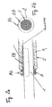
- Fig. 1 the schematic side elevation of an endoscope according to a first embodiment of the invention is shown.
- the endoscope according to the invention consists of an endoscope shaft 1, which is over a length of 1 to 2 m (usually about 1600 mm) with a everting tube 2 of Doppelstülpbauart or jacketed on both sides inverted.
- the distal end 3 of the endoscope shaft 1 consists of an angled in all directions or bendable end piece at the top of a lighting device and a camera chip are arranged (both not shown), which are routed via electrical lines that are routed within the endoscope shaft 1, on a camera control on rear end portion of the endoscope is connected.
- the camera is in turn connected to a monitor via a video processor.
- optics may also be provided at the tip of the bendable end piece 3, which may be connected via optical fibers, e.g. Fiber optic bundle within the endoscope shaft 1 is connected to the camera control.
- the endoscope shaft 1 further extends at least two channels or tubes, located at the foremost tip of the bendable end piece 3 open to the outside and have at the rear end portion of the endoscope an insertion port or manually controllable valves.
- One of these channels is used for the supply of air or gas and as a supply channel of cleaning fluid for flushing to examining points of the cavity, the other as a working channel for the introduction of medical equipment, which can be advanced to the distal end, for example, to take tissue samples or surgical procedures make.
- the everting tube 2 consists of an inner tube section 2a, which is slidably guided through a drive and guide sleeve or a tube guide member 5 and in its front region (everting region) is everted to a front outer tube section 2b.
- the front outer tube portion 2b is to the drive and guide sleeve (hose guide member) 5, which consists of a rigid material, preferably a plastic material, returned and attached at one axial end to the drive sleeve 5 such that it between the inner 2a and outer Hose section 2b comes to rest.
- the inner tube portion 2a is everted to a rear outer tube portion 2c, which is returned to the drive sleeve 5 and fixed to an axial end of the drive sleeve 5.
- the drive sleeve 5 serves on the one hand as a guide element for the inner tube portion 2a to prevent jarring and wrinkling and flaking and on the other hand as a connecting piece of the front outer 2b and rear outer tube section 2c, wherein a central region of the drive sleeve 5 exposed, that is not covered by the everting tube 2 remains.
- the drive sleeve 5 has at least one opening, preferably a longitudinal slot 6 of predetermined width extending in the axial direction.
- the material, ie the type of material and the material thickness of the everting tube 2 is selected such that in the front and rear Stülp Scheme 2d, 2e each a bead-shaped expansion due to an accumulation of material forms at the eversion, which in the inner region to a predetermined constriction the inner diameter of the everting tube 2 leads.
- the everting tube 2 is slidably attached to its front Stülp Scheme 2d to a conical front clamping piece 7, which sits firmly at least in the axial direction on the endoscope shaft 1 and tapers conically in the direction of penetration of the endoscope.
- the rear Stülp Scheme 2e of the everting tube 2 is also slidably attached to a rear clamping piece 8, which in this particular embodiment, just like the front clamping piece 7 sits firmly on the endoscope shaft 1 and also has a corresponding shape.
- the rear clamping piece 8 tapers conically opposite to the direction of penetration of the endoscope. It should be noted, however, that at least the rear clamping piece 8 may have any outer shape, since it is not introduced into the cavity to be examined.
- a narrow annular gap 9 is formed between the inner tube section 2a of the everting tube 2 and the endoscope shaft 1, which is delimited axially by the two beads in the everting regions 2d, 2e of the everting tube 2, which seal against the outer one Apply the lateral surface of the endoscope shaft 1.
- a drive or feed device 10 is arranged in the central region.
- This feed device 10 consists in the present case of a housing 11 preferably made of a plastic or a stainless metal alloy, in which the drive mechanism described below for the everting tube 2 according to the first second and third embodiments of the invention is housed.
- the housing 11 itself consists of two shell-shaped housing halves 11a, 11b, hinged together at a free edge portion along the drive sleeve 5 by means of a hinge or hinge, not shown, and are lockable on the opposite free edge portion by means of a locking device, also not shown.
- the housing halves 11a, 11b may of course also be completely divided and connectable by means of two locking devices.
- transverse side walls of the housing 11 are located on each housing half 11a, 11b of the outer cross-sectional shape of the drive sleeve 5 adapted recesses in the collapsed and locked state of the housing 11 each have a self-contained recess or opening profile corresponding to the outer contour of Form drive sleeve 5 and enclose them sealing to the outside.
- the recesses as well as the free edges of the housing halves 11a, 11b are provided at their respective cutting or edge surfaces with grooves 12 (not shown) in which sealing strips 13 are clamped or glued sealingly upon collapse of the housing halves 11a, 11b create the lateral surface of the drive sleeve 5 so as to create a Enclosing the housing interior sealingly.
- the drive and hose guide sleeve 5 in cross-section has a circular outer contour corresponding to the circular cross section of the forend tube 2 in order to ensure a dense and stress-free connection with the everting tube. But it may also have a lenticular or otherwise cross-sectional shape depending on the construction of the drive mechanism.
- This drive mechanism comprises according to the first preferred embodiment of the invention, a not further shown drive motor which acts via a gear train (also not shown) to a number of friction wheels 14.
- These friction wheels 14 are respectively mounted on the two housing halves 11a, 11b so that they penetrate into the folded or closed state of the housing 11 each in a longitudinal slot 6 of the drive sleeve 5 and with a predetermined preferably adjustable by springs contact pressure on the inner tube portion 2a of Slip tube 2 frictionally abut.
- the running surface of each drive wheel 14 is coated with an adhesive coating (coating with ceramic particles or metal granules of predetermined grain size) to increase the coefficient of friction between the everting tube 2 and the drive wheel 14.
- the friction wheels 14 can of course also be manufactured as a whole from a corresponding material, for example abrasive ceramics.
- the contact pressure is further selected depending on the material and the wall thickness of the everting tube 2 so that a uniform, substantially slip-free propulsion of the everting tube 2 is ensured by the friction wheels 14.
- the endoscope according to the first preferred embodiment of the invention is further provided with a lubricating system for lubricating the relative sliding movement between the endoscope shaft 1 and the inner tube section 2a, as well as between the inner and outer hose sections 2a, 2b, 2c, which will be described below.
- This lubrication system comprises a first Schmierstoffkeep- and feeding device 15 with a compressed air pump (not shown) or a compressed air connection, which is connected to a pressure vessel 18 in order to pressurize this with compressed air.
- This pressure vessel 18 has a hinged or removable cover 18a, by means of which a loading and unloading opening can be closed.
- a removable or replaceable plastic or rubber bag 18b Within the pressure vessel 18 is a removable or replaceable plastic or rubber bag 18b, or alternatively a masking agent bellows, which is filled with the lubricant to be used.
- This bag or bellows 18b has an outlet hose 18c, which is guided through a, preferably the connection point of the pump opposite bore of the pressure vessel 18.
- the bore closes off sealingly at the outlet hose 18c, for which purpose a sealing keder is attached to the bore in this embodiment. Additionally or alternatively to this seal, the bag 18 seals against the pressure vessel wall, so that the outlet bore is substantially airtight from the junction of the pump, which is preferably located in the lid 18a, separated by the bag 18b.
- a coupling piece 30 is provided, which is connectable to a corresponding coupling counterpart 31 of a supply tube 16 of the endoscope, which protrudes laterally from the rear end portion of the endoscope shaft 1 in particular from the housing of the actuator 4.
- the feed tube or channel 16 is here, as in the Fig. 1 is hinted, within the endoscope shaft 1 to a trained in the endoscope shaft 1 outlet bore 17 in the area of the everting tube 2 further.
- the two coupling pieces of the outlet 18c and the Feed tube 16 are in the Fig. 1a shown schematically.
- the one coupling piece 30 has a coupling flange with a union nut or a bayonet closure, wherein the mouth of the outlet tube 18c is closed by a membrane.
- the other coupling counterpart 31 has a counter-element corresponding to the union nut or the bayonet closure, and a cannula formed as a needle-shaped or cutting edge as the extreme end of the delivery tube 16.
- the cannula penetrates the membrane and thus establishes a fluid connection between the outlet tube 18c and the supply tube 16 ago.
- the arrangement of the coupling 30, 31 by no means must be on the endoscope.
- the one coupling piece 30 may for example also be integrated in the bore of the pressure vessel 18, in which case the counterpart 31 can be placed directly on the bag 18b so that upon insertion of the bag 18b a connection to the endoscope is automatically established.
- the first embodiment since this is already filled when plugging the two tubes 18c and 16 of the outlet hose 18c over its entire length with lubricant in advance and thus a subsequent venting of the lubrication system is no longer required.
- Fig. 1 As further in the Fig. 1 is shown penetrates the supply tube 16, the outlet hole 17, such that no lubricant can leak into the interior of the endoscope shaft 1, thereby emptying into the annular gap 9 between the inner everting tube portion 2a and the endoscope shaft 1, by the front and rear everting 2d, 2e is limited axially fluid-tight.
- the Supply tube 16 and the outlet tube 18c is connected directly to a terminal on the endoscope shaft 1, so that the supplied lubricant can spread within the entire endoscope shaft 1. That is, the endoscope shaft 1 in this case itself serves as part of the feed channel 16, the lubricant being conveyed via the feed tube 16 and the endoscope shaft 1 to the outlet bore 17. In this case, then all "innards" of the endoscope shaft 1 must be coated with a special coating or insulation or guided in channels to prevent contamination and related damage by the relatively aggressive lubricant.
- a perforation of the endoscope shaft 1 can also be provided at the corresponding point, wherein a separate lubricant line 16 with several leakers can be laid to the shaft surface in the endoscope shaft 1.
- the delivery pressure of the first lubricant delivery device 15 is selected so that the resulting back pressure within the annular gap 9 between the endoscope shaft 1 and the inner tube section 2a, smaller than the contact pressure of the bead-shaped Umstülp Societye 2d, 2e of the everting tube 2 on the endoscope shaft 1.
- the eversion areas 2d, 2e, together with the shaft 1, act directly as seals preventing leakage of lubricant.
- this type of seal initially does not have to slide along the endoscope shaft 1 or with a corresponding contact pressure on the front end piece 7 but systemeflower on the endoscope shaft 1 rolls, thereby increasing the necessary feed force on the inner tube section 2a to overcome frictional forces omitted.
- the lubrication system comprises a second lubricant delivery and delivery device 19, which is connected via a feed tube or channel 20 to the housing 11 of the drive device 10.
- the structural design of the second Schmierstoffhand- and supply device 19 corresponds in principle to that of the first Schmierstoffrion- and supply device 15 and the alternatives described for this purpose, so that reference can be made at this point to the corresponding text passages.
- the second Schmierstoffproof- and feeding device 19 connected to the drive housing 11 to press the subsidized lubricant in the sealed interior of the drive housing 11, wherein the coupling is disposed directly on the housing 11.
- This lubricant also has access via the openings or longitudinal slots 6 in the drive sleeve 5 access into the cavity between the inner and outer tube section 2a, 2b, 2c of the everting tube 2, thus the relative sliding movement between the inner and outer tube section 2a, 2b, 2c to lubricate.
- the lubricant within the drive housing 11 also causes lubrication of the drive mechanism, i. the storage of the friction wheels 14 itself.
- a vacuum tube 22, open at both ends, is drawn over the prefabricated everting tube 2, the inner diameter of which is slightly larger than the outer diameter of the outer tube section 2b, 2c.
- two sealing sleeves 23, 24 are then inserted.
- the outer part 25 of each gasket 23, 24 places itself sealingly against the Surface of the vacuum tube 22, while an inner part 26 of the sleeves 23, 24 acts against the inner tube portion 2a and this in the radial direction outwards, ie in the direction of the outer tube portion 2b, 2c suppressed.
- the vacuum tube 22 may also be split longitudinally into two half-shells, which are either hinged together at one longitudinal edge or completely separated. In this way, the insertion of the everting tube 2 is facilitated.
- the sealing collars 23, 24 can be replaced by an active spreading device (not shown), not shown in more detail, by means of which the turn-up regions 2e and 2d of the everting tube 2 can be pressed against the vacuum tube 22.
- This spreading device has, similar to a filling tongs, a number of (three) spreading elements, which are inserted into the hose mouth at the front and rear turn-up regions 2d, 2e.
- this spreading device can be further increased by a corresponding at both ends, for example, cloverleaf-shaped inner contour of the vacuum tube, which ensures that the hose not only at the points at which engage the spreading, but also between them on the pipe inner wall.
- the vacuum tube 22 may also be formed such that it has a cavity corresponding to the housing 11 of the drive device in the region of the drive sleeve 5, so that the entire everting tube system consisting of The everting tube, drive sleeve and drive device can be pre-mounted in the vacuum tube.
- the vacuum tube 22 further has a line connection 27, preferably in the region of the drive sleeve 5, which is connected via a line to a vacuum pump (not shown).
- a vacuum pump not shown
- the vacuum pump When the vacuum pump is put into operation, air is sucked out of the cavity between the vacuum tube 22 and the outer tube section 2b, 2c and between the outer and inner tube sections 2a, 2b, 2c via the opening 6 and the longitudinal grooves 5a of the drive sleeve 5, wherein the inner tube section 2a abuts against the outer tube section 2b, 2c and thereby enlarges the inner diameter of the everting tube 2 also in the area of the front and rear inversions 2d, 2e.
- the endoscope shaft 1 can now be inserted in a simple manner in the flared-over tube 2, whereby this threading process can be additionally facilitated by brushing the shaft 1 with a lubricant.
- the drive housing 11 is mounted on a pedestal, with respect to a plate on which the Patient is at least partially, height adjustable and in each direction is pivotable, so that the distal end 3 of the endoscope shaft 1 can be adjusted according to the individual physique of the patient. Subsequently, the distal end 3 of the endoscope shaft 1, ie a short distance inserted into the anus, until the everting tube 2 has passed the sphincter.
- CO2-Ga is introduced into the intestine via the endoscope shaft 1 or a channel guided therein, in order to deploy it, whereupon the drive device 10 is actuated in order to drive the friction wheels 14 with a predeterminable or during operation also changeable number of revolutions. According to this number of revolutions, the inner tube section 2a is slowly advanced in the direction of penetration of the endoscope, wherein it inverts continuously in the anterior everting region 2d to the front, outer tube section 2b and can laterally line the intestinal wall.
- the Umstülp Schemee 2d, 2e and the front and rear clamping pieces 7, 8 due to the low propulsion portion on the front clamping piece 7 and the low necessary braking force on the rear clamping piece 8 must not be pressed together so strong, for example, to achieve a sealing effect.
- this sealing effect is already achieved by the cooperation between the bulge-shaped eversion areas 2d, 2e and the endoscope shaft 2.
- the second lubricant delivery device 19 the lubricant is forced into the cavity between the inner and outer tube sections 2a, 2b, 2c at a predetermined pressure, thereby further reducing the frictional forces. This may be sufficient due to low leakage an initial lubrication process for filling the cavity between the outer and inner everting tube section, that is, that during at least one treatment time not necessarily lubricant must be nachgepreßt.
- an additional external synchronization drive means can be provided, which acts on the endoscope shaft 1 via a number of friction wheels at its rear end portion and thus ensures the continuous penetration movement of the endoscope.
- a spindle drive for the controlled continuous propulsion of the endoscope shaft 1 may be provided.
- the rear clamping piece 8 is designed as a hollow sleeve, which forms a substantially closed cavity together with the endoscope shaft 1.
- the rear hollow sleeve is axially symmetrically divisible in two half-shells so as to be better applied to the endoscope shaft 1 can.
- the side or contact wall 8a of the collar-shaped clamping piece 8 directed towards the everting tube 2 has at least one lubricant injection shoe 28 projecting in the region of the endoscope shaft 1, which protrudes in particular into the everting tube 2 Fig. 2b shown in its cross section.
- the lubricant injection shoe 28 extends at least a 1/3 circle or a 1/2 circle around the endoscope shaft 1.
- two diametrically opposed lubricant injection shoes 28 are provided, although in FIG Fig. 2b only one shoe is shown.
- the cavity described above can also be provided by a channel for supplying Be replaced lubricant.
- the lubricant injection shoes 28 are also elastically on at least at its outermost end portion on the lateral surface of the endoscope shaft 1 and each have at least one lubricant channel, as in Fig. 2a which opens at the rear end (root) of the lubricant injection shoe 28 into the cavity or the supply channel of the sleeve and at its front free end into the annular gap 9.
- a number of recesses or indentations can be provided in the side wall 8a of the sleeve 8, which form an exit gap or gap between the endoscope shaft 1 and the abutment wall 8a.
- the rear clamping piece 8 is provided with a line connection 8b which is fluidly connected to the first lubricant delivery device 15 via the supply line 16 and the outlet tube 18c. All other parts of the endoscope according to the Fig. 2 correspond to those of the first embodiment.
- the first lubricant delivery device 15 conveys the lubricant into the cavity within the rear cuff-shaped clamping piece 8, which fills up accordingly.
- the lubricant flows out of the lubricant channel within the lubricant injection shoe 28 or from the gaps in the abutment wall 8a and penetrates into the annular gap 9 between the endoscope shaft 1 and the inner tube section 2a of the everting tube 2 for lubricating the relative Sliding movement of both components.
- the rear inversion region 2e of the everting tube 2 acts as Seal, against the shaft 1 and against the contact side 8a of the rear clamping piece 8. Also encompasses the rear everting tube portion of the lubricant injection shoe 28 sealingly over its entire length ..
- the drive of the endoscope can be done by components different from the friction wheels 14.
- 2 gears could be provided for the advancing device 10 of the everting tube, which act on the inner tube section 2a.
- all of these variants have in common that the radial pressure force is sufficient to push the inner tube section 2a against the endoscope shaft 1 for its continuous drive despite the presence of lubricant, thereby enabling the exact positioning of the distal end at a point to be examined ,
- the drive device of the third embodiment consists of a drive housing 11 which is placed around the hose guide sleeve 5 as in the first and second embodiments and in which at least two vacuum grippers are arranged alternately movable in the axial direction of the endoscope shaft 1.
- the vacuum grippers consist of small, through the openings in the drive sleeve 5 through, tightly against the inner everting tube section 2a blocks with suction cups, which are formed on the side in contact with the tube 2a of the blocks and suck the generated by a vacuum pump vacuum the tubing in the region of the inner everting tube section 2a and so on produce positive and positive connection to the inner hose section 2a.
- the vacuum pump (not shown) is for this purpose connected to a vacuum connection, which is formed in the housing 11 of the drive device 10 and connected via channels within the blocks with the Suagnäpfen.
- the movement of the blocks which is accomplished by a movement mechanism, not shown, as well as generating the negative pressure within the suction cups is controlled so that the blocks alternately or more than two blocks at regular intervals continuously with a synchronous suction and release of the inner Everting tube section 2a are reciprocated and thereby produce a quasi-continuous and uniform feed movement of the everting tube 2.
- the vacuumizing of the suction cups causes a slight lifting of the inner everting tube portion 2a from the endoscope shaft.
- the feed force to the endoscope shaft 1 is carried out in this embodiment substantially as in the previous versions.
- the entire assembly is filled as in the first and second embodiments with a lubricant that takes over the lubrication of the everting tube 2.
- the Fig. 6 shows an alternative embodiment to the third embodiment, in which by generating a negative pressure, a driving force on the everting tube can be applied.
- the drive mechanism of the third embodiment is formed by a kind of caterpillar drive consisting of at least one elastic endless belt, which is stretched and driven by at least two spaced in the feed direction wheels.
- the entire drive device is housed in the preferably two-part, airtight sealable housing in the longitudinal direction, which has a suction port.
- the endless belt has a number of openings or a perforation on its surface.
- the suction port is connected via a hose to a vacuum pump, not shown.
- the housing 11 itself is open on its side facing the inner tube section 2a, wherein the endless belt is guided in such a way that it closes the open side of the housing 11 as tightly as possible. Gaps between the side edges of the endless belt and the housing 11 may be closed by suitable sealing lips which are secured to the housing walls and on which the endless belt slides. Furthermore, the housing 11 is arranged with respect to the Stülpschlaüchs 2 attached thereto such that the outwardly exposed side of the endless belt with a small gap or distance above the inner tube portion 2a aligns.
- the interior of the housing 11 is evacuated by the vacuum pump, whereby air is sucked through the perforation in the endless belt.
- the inner tube section 2a is sucked with, which applies sealingly to the outside of the endless belt.
- This sealing of the perforation increases the negative pressure within the housing such that the endless belt bulges inwardly due to its elasticity and thereby entrains the inner hose section 2a, as in the Fig. 6 clearly shown.
- the inner tube portion 2a is held firmly over the length of the endless belt and at the same time spaced from the endoscope shaft 1.
- the propulsion of the endoscope shaft 1 thus takes place essentially by the contact forces which are applied to the front clamping piece 7 by the endless belt at the front everting portion 2d during an advancing movement of the front outer hose portion 2b, whereby the inner hose portion 2a remains contactless, in particular in the region of the drive unit.
- Due to the low frictional forces the necessary feed force on the front clamping piece 7 is relatively low, so that no dandruff (wrinkling) in the front portion of the everting tube 2 is to be expected.
- a lubricant is pressed into the annular gap 9, whereby the friction, in particular in the region of the front and rear sealing beads 2d, 2e is further reduced.
- the third embodiment as well as its alternative embodiment provides, as in the first and second embodiments, a continuously or quasi-continuously acting mechnisch acting on the everting tube 2 drive mechanism, which ensures a precisely controllable locomotion of the endoscope.
- the invention relates to an everting tube system having an endoscope having an inner shaft which is guided in a everting tube of the Doppelstülpbauart.
- the drive of the tube is via a number of friction wheels, suction cups or beads which act on an inner tube section to drive the system for continuous movement.
- front and rear everting regions each form a protuberance which seals against the shaft.
- the supply of lubricant into the gap between the shaft and inner tube section via a substantially radial shaft bore in the region of the everting tube, which is connected either via the shaft cavity or an inner conduit to an external supply or via a rear clamping piece by means of a shaft surface adapted lubricant injection shoe ,
Landscapes
- Health & Medical Sciences (AREA)
- Life Sciences & Earth Sciences (AREA)
- Surgery (AREA)
- Heart & Thoracic Surgery (AREA)
- Biophysics (AREA)
- Veterinary Medicine (AREA)
- Public Health (AREA)
- General Health & Medical Sciences (AREA)
- Animal Behavior & Ethology (AREA)
- Engineering & Computer Science (AREA)
- Biomedical Technology (AREA)
- Medical Informatics (AREA)
- Physics & Mathematics (AREA)
- Molecular Biology (AREA)
- Radiology & Medical Imaging (AREA)
- Pathology (AREA)
- Optics & Photonics (AREA)
- Nuclear Medicine, Radiotherapy & Molecular Imaging (AREA)
- Gastroenterology & Hepatology (AREA)
- Pulmonology (AREA)
- Anesthesiology (AREA)
- Hematology (AREA)
- Endoscopes (AREA)
- Rolls And Other Rotary Bodies (AREA)
- Rigid Pipes And Flexible Pipes (AREA)
- Instruments For Viewing The Inside Of Hollow Bodies (AREA)
Claims (1)
- Endoscope avec une tige interne (1) conduite de façon coulissante dans une gaine (2) retroussée à ses deux extrémités, qui se déplace grâce à un dispositif d'entraînement (10) qui agit sur une section de gaine (2a) interne de la gaine retroussée (2) caractérisé en ce que la gaine retroussée (2) a une douille de guidage de gaine (5) en une matière rigide, qui présente dans sa partie centrale une pluralité d'ouvertures et qui s'étend sur la section interne (2a) de la gaine en formant un intervalle, que les extrémités libres des sections externes (2b, 2c) de la gaine sont fixées sur ses deux extrémités axiales, extrémités libres (2b, 2c) qui sont formées par retroussement et retour de la section interne (2a) de la gaine dans deux zone de retroussement (2d, 2e) espacées axialement, la douille (5) étant entourée d'un boîtier en deux parties (11) repliable, en forme de manchon, qui, à l'état fermé, forme avec la douille (5) une chambre fermée de façon étanche vers l'extérieur dans laquelle sont introduits des galets de frottement (14), qui, en s'appuyant sur le boîtier, sont pressés lorsque le boîtier est refermé, à travers les ouvertures de la douille (6) contre la section de gaine (2a) interne, et qu'un raccord est formé sur le boîtier (11) pour l'alimentation en lubrifiant grâce à un dispositif de déplacement et de conduite de lubrifiant (19) qui peut être pressé dans la chambre de la gaine retroussée à travers les ouvertures de la douille (6).
Applications Claiming Priority (3)
| Application Number | Priority Date | Filing Date | Title |
|---|---|---|---|
| DE19717108A DE19717108A1 (de) | 1997-04-23 | 1997-04-23 | Stülpschlauchsystem |
| EP98105235A EP0873761B1 (fr) | 1997-04-23 | 1998-03-23 | Système à manchon inversé |
| EP04006220A EP1433411B1 (fr) | 1997-04-23 | 1998-03-23 | Système à manchon inversé |
Related Parent Applications (1)
| Application Number | Title | Priority Date | Filing Date |
|---|---|---|---|
| EP04006220A Division EP1433411B1 (fr) | 1997-04-23 | 1998-03-23 | Système à manchon inversé |
Publications (3)
| Publication Number | Publication Date |
|---|---|
| EP1676598A2 EP1676598A2 (fr) | 2006-07-05 |
| EP1676598A3 EP1676598A3 (fr) | 2008-07-09 |
| EP1676598B1 true EP1676598B1 (fr) | 2009-09-02 |
Family
ID=7827474
Family Applications (4)
| Application Number | Title | Priority Date | Filing Date |
|---|---|---|---|
| EP98105235A Expired - Lifetime EP0873761B1 (fr) | 1997-04-23 | 1998-03-23 | Système à manchon inversé |
| EP06113057A Withdrawn EP1676597A3 (fr) | 1997-04-23 | 1998-03-23 | Système à machon inversé |
| EP04006220A Expired - Lifetime EP1433411B1 (fr) | 1997-04-23 | 1998-03-23 | Système à manchon inversé |
| EP06113059A Expired - Lifetime EP1676598B1 (fr) | 1997-04-23 | 1998-03-23 | Système à machon inversé |
Family Applications Before (3)
| Application Number | Title | Priority Date | Filing Date |
|---|---|---|---|
| EP98105235A Expired - Lifetime EP0873761B1 (fr) | 1997-04-23 | 1998-03-23 | Système à manchon inversé |
| EP06113057A Withdrawn EP1676597A3 (fr) | 1997-04-23 | 1998-03-23 | Système à machon inversé |
| EP04006220A Expired - Lifetime EP1433411B1 (fr) | 1997-04-23 | 1998-03-23 | Système à manchon inversé |
Country Status (7)
| Country | Link |
|---|---|
| US (1) | US6077219A (fr) |
| EP (4) | EP0873761B1 (fr) |
| JP (1) | JP4391605B2 (fr) |
| AT (3) | ATE441353T1 (fr) |
| CA (1) | CA2231761A1 (fr) |
| DE (4) | DE19717108A1 (fr) |
| ES (3) | ES2232894T3 (fr) |
Families Citing this family (82)
| Publication number | Priority date | Publication date | Assignee | Title |
|---|---|---|---|---|
| US6511512B2 (en) * | 1998-04-10 | 2003-01-28 | Ossur Hf | Active shock module prosthesis |
| DE29808180U1 (de) * | 1998-05-06 | 1998-07-23 | STM Medizintechnik Starnberg GmbH, 86947 Weil | Antriebseinrichtung für Stülpschlauchsystem |
| JP3071190B2 (ja) * | 1998-08-26 | 2000-07-31 | 昌純 高田 | 自走式大腸内視鏡及びその洗浄方法 |
| US6699179B2 (en) * | 2000-01-27 | 2004-03-02 | Scimed Life Systems, Inc. | Catheter introducer system for exploration of body cavities |
| US6517477B1 (en) | 2000-01-27 | 2003-02-11 | Scimed Life Systems, Inc. | Catheter introducer system for exploration of body cavities |
| WO2001070097A1 (fr) * | 2000-03-23 | 2001-09-27 | Atropos Limited | Dispositif d'insertion pour endoscope |
| IL138237A (en) * | 2000-09-04 | 2008-12-29 | Stryker Gi Ltd | Double sleeve endoscope |
| US6702735B2 (en) | 2000-10-17 | 2004-03-09 | Charlotte Margaret Kelly | Device for movement along a passage |
| US7041051B2 (en) * | 2001-04-26 | 2006-05-09 | Lionel M. Bernstein | Automated self-propelling endoscope |
| US7635342B2 (en) * | 2001-05-06 | 2009-12-22 | Stereotaxis, Inc. | System and methods for medical device advancement and rotation |
| WO2003015848A1 (fr) * | 2001-08-14 | 2003-02-27 | Applied Medical Resources Corporation | Procede et appareil de fermeture hermetique d'un acces |
| US20030220544A1 (en) * | 2002-05-21 | 2003-11-27 | Chang Stanley F. | Method of delivering lubricant for endoscopic procedures |
| US6872178B2 (en) * | 2002-11-18 | 2005-03-29 | Andrew Mark Weinberg | Colonoscope apparatus and method |
| WO2004060149A1 (fr) * | 2003-01-03 | 2004-07-22 | Kress Juergen | Element de protection hygienique pour endoscope |
| DE10310912A1 (de) * | 2003-03-13 | 2004-09-23 | Lübbe, Manfred | Aufsatzpads als Vorrichtung zum Verändern des Nahsichtsfeldes einer Nah-, Stufen- oder Gleitsichtbrille |
| US7736300B2 (en) | 2003-04-14 | 2010-06-15 | Softscope Medical Technologies, Inc. | Self-propellable apparatus and method |
| US6971990B2 (en) * | 2003-04-14 | 2005-12-06 | Troy J. Ziegler | Propulsion mechanism for endoscopic systems |
| AU2004263142A1 (en) | 2003-08-06 | 2005-02-17 | Applied Medical Resources Corporation | Surgical device with tack-free gel and method of manufacture |
| US6908428B2 (en) * | 2003-09-04 | 2005-06-21 | Sightline Technologies Ltd. | Sleeve for endoscopic tools |
| EP1943939B1 (fr) * | 2004-01-30 | 2019-02-27 | FUJIFILM Corporation | Applicateur d'endoscope et appareil d'endoscope |
| JP3962999B2 (ja) * | 2004-03-29 | 2007-08-22 | 有限会社エスアールジェイ | 内視鏡装置 |
| DE102004052036A1 (de) * | 2004-10-26 | 2006-04-27 | Stm Medizintechnik Starnberg Gmbh | Endoskop mit alternierendem Vortrieb |
| DE102005004622A1 (de) * | 2005-02-01 | 2006-08-10 | Stm Medizintechnik Starnberg Gmbh | Endoskop mit längsgeführtem Stülpschlauch |
| US7708687B2 (en) * | 2005-05-27 | 2010-05-04 | Bern M Jonathan | Endoscope propulsion system and method |
| DE102005048675A1 (de) * | 2005-10-11 | 2007-04-12 | Invendo Medical Gmbh | Medizintechnische Vorrichtung mit selbstschmierendem Element |
| WO2007103826A2 (fr) * | 2006-03-02 | 2007-09-13 | Talus Medical, Inc. | Prothèse osseuse |
| DE102006000435A1 (de) * | 2006-09-01 | 2008-03-06 | Invendo Medical Gmbh | Stülpschlauch mit 2-Komponentenschmiermittel |
| DE102007000200A1 (de) * | 2007-04-03 | 2008-10-09 | Invendo Medical Gmbh | Druckmesseinrichtung |
| DE102007000214A1 (de) * | 2007-04-10 | 2008-10-16 | Invendo Medical Gmbh | Verfahren zur Reibungsverringerung eines medizintechnischen Kautschukschlauchs |
| JP2013505058A (ja) * | 2009-09-17 | 2013-02-14 | 富士フイルム株式会社 | 能動的にサイズを変える機能を備える推進装置 |
| DE102009052386B4 (de) * | 2009-11-09 | 2019-03-14 | Invendo Medical Gmbh | Schmiermittelzuführeinrichtung für den Stülpschlauchantrieb eines Endoskops |
| DE102009052688A1 (de) * | 2009-11-11 | 2011-05-12 | Invendo Medical Gmbh | Endoskopschaft aus einem Verbundschlauch |
| US20130317519A1 (en) | 2012-05-25 | 2013-11-28 | Hansen Medical, Inc. | Low friction instrument driver interface for robotic systems |
| DE102012218148B4 (de) | 2012-10-04 | 2023-03-02 | Digital Endoscopy Gmbh | Baugruppe aus einem stülpschlauch und einem endoskoprohr |
| DE102012218147B4 (de) * | 2012-10-04 | 2023-03-02 | Digital Endoscopy Gmbh | Baugruppe aus einem stülpschlauch und einem endoskoprohr |
| US11213363B2 (en) | 2013-03-14 | 2022-01-04 | Auris Health, Inc. | Catheter tension sensing |
| US9326822B2 (en) | 2013-03-14 | 2016-05-03 | Hansen Medical, Inc. | Active drives for robotic catheter manipulators |
| US20140277334A1 (en) | 2013-03-14 | 2014-09-18 | Hansen Medical, Inc. | Active drives for robotic catheter manipulators |
| US9173713B2 (en) | 2013-03-14 | 2015-11-03 | Hansen Medical, Inc. | Torque-based catheter articulation |
| US20140276936A1 (en) | 2013-03-15 | 2014-09-18 | Hansen Medical, Inc. | Active drive mechanism for simultaneous rotation and translation |
| US9408669B2 (en) | 2013-03-15 | 2016-08-09 | Hansen Medical, Inc. | Active drive mechanism with finite range of motion |
| US20140276647A1 (en) | 2013-03-15 | 2014-09-18 | Hansen Medical, Inc. | Vascular remote catheter manipulator |
| US9693676B2 (en) * | 2013-05-10 | 2017-07-04 | J. Mathieu Massicotte | Toroidal balloon-driven vehicle |
| JP6656148B2 (ja) | 2013-10-24 | 2020-03-04 | オーリス ヘルス インコーポレイテッド | ロボット支援管腔内手術のためのシステムおよび関連する方法 |
| US10046140B2 (en) | 2014-04-21 | 2018-08-14 | Hansen Medical, Inc. | Devices, systems, and methods for controlling active drive systems |
| US10569052B2 (en) | 2014-05-15 | 2020-02-25 | Auris Health, Inc. | Anti-buckling mechanisms for catheters |
| US9561083B2 (en) | 2014-07-01 | 2017-02-07 | Auris Surgical Robotics, Inc. | Articulating flexible endoscopic tool with roll capabilities |
| CN104207747B (zh) * | 2014-09-28 | 2015-10-07 | 烟台蚯蚓窥视镜有限公司 | 内窥镜导管游动推进装置 |
| CN104207748B (zh) * | 2014-10-06 | 2015-10-07 | 王禄科 | 膜管延展式内窥镜导管推进装置 |
| CN104305948B (zh) * | 2014-11-03 | 2015-11-11 | 烟台蚯蚓窥视镜有限公司 | 胶囊式内窥镜推进装置 |
| CN104287688B (zh) * | 2014-11-07 | 2015-11-11 | 王禄科 | 前端加压膜管延展式内窥镜导管推进装置 |
| JP6769956B2 (ja) * | 2014-11-11 | 2020-10-14 | オーテック リミテッド | スリーブを備えた中空プローブ |
| CN113229942B (zh) | 2015-09-09 | 2024-11-12 | 奥瑞斯健康公司 | 手术器械装置操纵器 |
| US9955986B2 (en) | 2015-10-30 | 2018-05-01 | Auris Surgical Robotics, Inc. | Basket apparatus |
| US9949749B2 (en) | 2015-10-30 | 2018-04-24 | Auris Surgical Robotics, Inc. | Object capture with a basket |
| US10231793B2 (en) | 2015-10-30 | 2019-03-19 | Auris Health, Inc. | Object removal through a percutaneous suction tube |
| JP6978431B2 (ja) * | 2016-04-21 | 2021-12-08 | ベイラー カレッジ オブ メディスンBaylor College Of Medicine | トロカール |
| US10454347B2 (en) | 2016-04-29 | 2019-10-22 | Auris Health, Inc. | Compact height torque sensing articulation axis assembly |
| US11241559B2 (en) | 2016-08-29 | 2022-02-08 | Auris Health, Inc. | Active drive for guidewire manipulation |
| KR20230096148A (ko) | 2016-08-31 | 2023-06-29 | 아우리스 헬스, 인코포레이티드 | 길이 보존 수술용 기구 |
| US10244926B2 (en) | 2016-12-28 | 2019-04-02 | Auris Health, Inc. | Detecting endolumenal buckling of flexible instruments |
| WO2018184717A2 (fr) | 2017-04-06 | 2018-10-11 | Christoph Miethke Gmbh & Co. Kg | Réducteur de débit |
| CN110573208B (zh) | 2017-04-06 | 2022-11-08 | 克里斯托夫梅斯克两合公司 | 流量减少器 |
| US11026758B2 (en) | 2017-06-28 | 2021-06-08 | Auris Health, Inc. | Medical robotics systems implementing axis constraints during actuation of one or more motorized joints |
| US11576560B2 (en) * | 2017-10-19 | 2023-02-14 | Ottek Ltd. | Hollow probe with sleeve |
| US10470830B2 (en) | 2017-12-11 | 2019-11-12 | Auris Health, Inc. | Systems and methods for instrument based insertion architectures |
| US11510736B2 (en) | 2017-12-14 | 2022-11-29 | Auris Health, Inc. | System and method for estimating instrument location |
| WO2019143458A1 (fr) | 2018-01-17 | 2019-07-25 | Auris Health, Inc. | Systèmes robotiques chirurgicaux dotés de bras robotiques améliorés |
| EP3813632B1 (fr) | 2018-06-27 | 2026-04-22 | Auris Health, Inc. | Systèmes d'alignement et de fixation pour instruments médicaux |
| EP3856001A4 (fr) * | 2018-09-28 | 2022-06-22 | Auris Health, Inc. | Dispositifs, systèmes et méthodes d'entraînement manuel et robotique d'instruments médicaux |
| US11730941B2 (en) * | 2019-03-18 | 2023-08-22 | Covidien Lp | Surgical tool positioning device |
| EP3908224A4 (fr) | 2019-03-22 | 2022-10-19 | Auris Health, Inc. | Systèmes et procédés d'alignements d'entrées sur des instruments médicaux |
| US11896330B2 (en) | 2019-08-15 | 2024-02-13 | Auris Health, Inc. | Robotic medical system having multiple medical instruments |
| US11737845B2 (en) | 2019-09-30 | 2023-08-29 | Auris Inc. | Medical instrument with a capstan |
| KR20220123269A (ko) | 2019-12-31 | 2022-09-06 | 아우리스 헬스, 인코포레이티드 | 고급 바스켓 구동 모드 |
| WO2021137104A1 (fr) | 2019-12-31 | 2021-07-08 | Auris Health, Inc. | Système de poulie dynamique |
| IL272441B (en) * | 2020-02-03 | 2021-08-31 | Ottek Ltd | System and method for driving an endoscope |
| CA3189848A1 (fr) * | 2020-08-19 | 2022-02-24 | Satwinder S. Panesar | Compteur intelligent pour hydratation et insertion de catheter |
| DE102020134312B3 (de) | 2020-12-18 | 2022-01-05 | Christoph Miethke Gmbh & Co Kg | Einstellbare implantierbare Drossel |
| DE102021102887B3 (de) * | 2021-02-08 | 2022-04-21 | Schölly Fiberoptic GmbH | Kupplungsvorrichtung für Lichtleiter |
| CN114732346A (zh) * | 2022-03-21 | 2022-07-12 | 杭州康基医疗器械有限公司 | 宫腔镜 |
| EP4569244A1 (fr) * | 2022-08-10 | 2025-06-18 | Corning Research & Development Corporation | Procédé et système de commande de la tension sur un tube tampon par une chenille de compression sur une ligne tampon |
Family Cites Families (8)
| Publication number | Priority date | Publication date | Assignee | Title |
|---|---|---|---|---|
| DE2406823A1 (de) * | 1974-02-13 | 1975-08-14 | Peter Udo | Verfahren und vorrichtung zur katheterisierung von geraden oder gewundenen roehren- und gefaessystemen |
| US4211233A (en) * | 1978-01-05 | 1980-07-08 | Lin Edward D | Urethral catheter |
| JPS60501696A (ja) * | 1983-06-28 | 1985-10-11 | シユテリメ−ト ゲゼルシヤフト フユ−ル メデイツイ−ニツシエンベダルフ ミツト ベシユレンクテル ハフツング | 導入補助装置を有する医療装置 |
| US5236423A (en) * | 1988-12-13 | 1993-08-17 | Endomed Corporation | Facilitating endoscopy |
| US5045070A (en) * | 1988-12-22 | 1991-09-03 | Pentotech, Ltd. | Body cavity probe with everting tube |
| DE3925484A1 (de) * | 1989-08-01 | 1991-02-07 | Bob Konstantin | Vorrichtung zum einfuehren eines medizinischen endoskops in einen koerperkanal |
| DE4244990C2 (de) * | 1992-12-15 | 2002-03-14 | Stm Medtech Starnberg | Vorrichtung zum Bewegen eines Endoskopschafts längs eines kanalartigen Hohlraums |
| DE4242291C2 (de) * | 1992-12-15 | 2000-02-10 | Stm Medtech Starnberg | Vorrichtung zum Bewegen eines Endoskops längs eines kanalartigen Hohlraums |
-
1997
- 1997-04-23 DE DE19717108A patent/DE19717108A1/de not_active Ceased
-
1998
- 1998-03-11 CA CA002231761A patent/CA2231761A1/fr not_active Abandoned
- 1998-03-23 EP EP98105235A patent/EP0873761B1/fr not_active Expired - Lifetime
- 1998-03-23 EP EP06113057A patent/EP1676597A3/fr not_active Withdrawn
- 1998-03-23 ES ES98105235T patent/ES2232894T3/es not_active Expired - Lifetime
- 1998-03-23 AT AT06113059T patent/ATE441353T1/de not_active IP Right Cessation
- 1998-03-23 ES ES04006220T patent/ES2299769T3/es not_active Expired - Lifetime
- 1998-03-23 DE DE59814390T patent/DE59814390D1/de not_active Expired - Lifetime
- 1998-03-23 AT AT04006220T patent/ATE383808T1/de not_active IP Right Cessation
- 1998-03-23 DE DE59814155T patent/DE59814155D1/de not_active Expired - Lifetime
- 1998-03-23 DE DE59812233T patent/DE59812233D1/de not_active Expired - Lifetime
- 1998-03-23 AT AT98105235T patent/ATE281866T1/de not_active IP Right Cessation
- 1998-03-23 ES ES06113059T patent/ES2334052T3/es not_active Expired - Lifetime
- 1998-03-23 EP EP04006220A patent/EP1433411B1/fr not_active Expired - Lifetime
- 1998-03-23 EP EP06113059A patent/EP1676598B1/fr not_active Expired - Lifetime
- 1998-04-22 JP JP11176498A patent/JP4391605B2/ja not_active Expired - Lifetime
- 1998-04-23 US US09/065,653 patent/US6077219A/en not_active Expired - Lifetime
Also Published As
| Publication number | Publication date |
|---|---|
| JPH10314109A (ja) | 1998-12-02 |
| US6077219A (en) | 2000-06-20 |
| EP1433411B1 (fr) | 2008-01-16 |
| ATE281866T1 (de) | 2004-11-15 |
| ES2334052T3 (es) | 2010-03-04 |
| EP1433411A3 (fr) | 2004-10-06 |
| ATE383808T1 (de) | 2008-02-15 |
| DE59814155D1 (de) | 2008-03-06 |
| DE59812233D1 (de) | 2004-12-16 |
| EP1676598A2 (fr) | 2006-07-05 |
| EP1676597A3 (fr) | 2008-07-09 |
| EP0873761A1 (fr) | 1998-10-28 |
| DE19717108A1 (de) | 1998-11-05 |
| JP4391605B2 (ja) | 2009-12-24 |
| ES2232894T3 (es) | 2005-06-01 |
| ATE441353T1 (de) | 2009-09-15 |
| EP1676598A3 (fr) | 2008-07-09 |
| EP1433411A2 (fr) | 2004-06-30 |
| CA2231761A1 (fr) | 1998-10-23 |
| ES2299769T3 (es) | 2008-06-01 |
| DE59814390D1 (de) | 2009-10-15 |
| EP1676597A2 (fr) | 2006-07-05 |
| EP0873761B1 (fr) | 2004-11-10 |
Similar Documents
| Publication | Publication Date | Title |
|---|---|---|
| EP1676598B1 (fr) | Système à machon inversé | |
| EP0993277B1 (fr) | Trocart flexible avec systeme de tube souple a recouvrement | |
| DE19748500B4 (de) | Vorschubeinrichtung für einen flexiblen Endoskopschaft | |
| DE19920717B4 (de) | Antriebseinrichtung für Stülpschlauchsystem | |
| EP0497781B1 (fr) | Dispositif d'introduction pour appareils tubulaires en fibres optiques, notamment pour colonoscope | |
| EP0955006A1 (fr) | Dispositif d'avancement d'un endoscope dans un conduit | |
| EP0484458A1 (fr) | Endoscope. | |
| EP1034010B1 (fr) | Dispositif d'aide a l'insertion endoscopique | |
| DE4242291C2 (de) | Vorrichtung zum Bewegen eines Endoskops längs eines kanalartigen Hohlraums | |
| EP1654976B1 (fr) | Endoscope à progression alternée | |
| EP1685789A2 (fr) | Endoscope avec un tube retourné, guidé longitudinalement | |
| EP3466480A1 (fr) | Dispositif de connexion pour tubes d'étalonnage gastriques ainsi que système médical doté d'un dispositif de connexion pour tubes d'étalonnage gastriques et d'un tube d'étalonnage gastrique | |
| WO2018010034A1 (fr) | Dispositif d'utilisation de soutien pendant la colonoscopie, en particulier permettant de fixer et, de préférence, d'étanchéifier un endoscope dans la zone du canal anal et/ou du rectum | |
| EP2903494B1 (fr) | Système d'endoscopie et de biopsie à usage unique | |
| DE10111354A1 (de) | Endoskopisches Intstument mit Gleitmittelbeaufschlagung | |
| DE102012218147B4 (de) | Baugruppe aus einem stülpschlauch und einem endoskoprohr | |
| EP2478829A1 (fr) | Dispositif d'introduction d'un instrument dans un corps creux | |
| DE102012218148B4 (de) | Baugruppe aus einem stülpschlauch und einem endoskoprohr | |
| DE20012624U1 (de) | Flexible Trokarhülse |
Legal Events
| Date | Code | Title | Description |
|---|---|---|---|
| PUAI | Public reference made under article 153(3) epc to a published international application that has entered the european phase |
Free format text: ORIGINAL CODE: 0009012 |
|
| 17P | Request for examination filed |
Effective date: 20060524 |
|
| AC | Divisional application: reference to earlier application |
Ref document number: 0873761 Country of ref document: EP Kind code of ref document: P Ref document number: 1433411 Country of ref document: EP Kind code of ref document: P |
|
| AK | Designated contracting states |
Kind code of ref document: A2 Designated state(s): AT BE BG CH CY CZ DE DK EE ES FI FR GB GR HU IE IS IT LI LT LU LV MC NL PL PT RO SE SI SK TR |
|
| AX | Request for extension of the european patent |
Extension state: AL BA HR MK YU |
|
| PUAL | Search report despatched |
Free format text: ORIGINAL CODE: 0009013 |
|
| AK | Designated contracting states |
Kind code of ref document: A3 Designated state(s): AT BE BG CH CY CZ DE DK EE ES FI FR GB GR HU IE IS IT LI LT LU LV MC NL PL PT RO SE SI SK TR |
|
| AX | Request for extension of the european patent |
Extension state: AL BA HR MK YU |
|
| RIC1 | Information provided on ipc code assigned before grant |
Ipc: A61B 1/31 20060101ALI20080530BHEP Ipc: A61M 25/01 20060101ALI20080530BHEP Ipc: A61B 1/01 20060101AFI20080530BHEP |
|
| GRAP | Despatch of communication of intention to grant a patent |
Free format text: ORIGINAL CODE: EPIDOSNIGR1 |
|
| AKX | Designation fees paid |
Designated state(s): AT CH DE ES FR GB IT LI SE |
|
| GRAS | Grant fee paid |
Free format text: ORIGINAL CODE: EPIDOSNIGR3 |
|
| GRAA | (expected) grant |
Free format text: ORIGINAL CODE: 0009210 |
|
| AC | Divisional application: reference to earlier application |
Ref document number: 0873761 Country of ref document: EP Kind code of ref document: P Ref document number: 1433411 Country of ref document: EP Kind code of ref document: P |
|
| AK | Designated contracting states |
Kind code of ref document: B1 Designated state(s): AT CH DE ES FR GB IT LI SE |
|
| REG | Reference to a national code |
Ref country code: CH Ref legal event code: EP |
|
| REF | Corresponds to: |
Ref document number: 59814390 Country of ref document: DE Date of ref document: 20091015 Kind code of ref document: P |
|
| REG | Reference to a national code |
Ref country code: CH Ref legal event code: NV Representative=s name: E. BLUM & CO. AG PATENT- UND MARKENANWAELTE VSP |
|
| PG25 | Lapsed in a contracting state [announced via postgrant information from national office to epo] |
Ref country code: SE Free format text: LAPSE BECAUSE OF FAILURE TO SUBMIT A TRANSLATION OF THE DESCRIPTION OR TO PAY THE FEE WITHIN THE PRESCRIBED TIME-LIMIT Effective date: 20090902 |
|
| REG | Reference to a national code |
Ref country code: ES Ref legal event code: FG2A Ref document number: 2334052 Country of ref document: ES Kind code of ref document: T3 |
|
| PGFP | Annual fee paid to national office [announced via postgrant information from national office to epo] |
Ref country code: ES Payment date: 20100324 Year of fee payment: 13 Ref country code: CH Payment date: 20100325 Year of fee payment: 13 |
|
| PGFP | Annual fee paid to national office [announced via postgrant information from national office to epo] |
Ref country code: AT Payment date: 20100322 Year of fee payment: 13 |
|
| PLBE | No opposition filed within time limit |
Free format text: ORIGINAL CODE: 0009261 |
|
| STAA | Information on the status of an ep patent application or granted ep patent |
Free format text: STATUS: NO OPPOSITION FILED WITHIN TIME LIMIT |
|
| 26N | No opposition filed |
Effective date: 20100603 |
|
| PGFP | Annual fee paid to national office [announced via postgrant information from national office to epo] |
Ref country code: IT Payment date: 20100327 Year of fee payment: 13 |
|
| REG | Reference to a national code |
Ref country code: CH Ref legal event code: PL |
|
| PG25 | Lapsed in a contracting state [announced via postgrant information from national office to epo] |
Ref country code: AT Free format text: LAPSE BECAUSE OF NON-PAYMENT OF DUE FEES Effective date: 20110323 |
|
| PG25 | Lapsed in a contracting state [announced via postgrant information from national office to epo] |
Ref country code: LI Free format text: LAPSE BECAUSE OF NON-PAYMENT OF DUE FEES Effective date: 20110331 Ref country code: CH Free format text: LAPSE BECAUSE OF NON-PAYMENT OF DUE FEES Effective date: 20110331 |
|
| PG25 | Lapsed in a contracting state [announced via postgrant information from national office to epo] |
Ref country code: IT Free format text: LAPSE BECAUSE OF NON-PAYMENT OF DUE FEES Effective date: 20110323 |
|
| REG | Reference to a national code |
Ref country code: ES Ref legal event code: FD2A Effective date: 20120424 |
|
| PG25 | Lapsed in a contracting state [announced via postgrant information from national office to epo] |
Ref country code: ES Free format text: LAPSE BECAUSE OF NON-PAYMENT OF DUE FEES Effective date: 20110324 |
|
| REG | Reference to a national code |
Ref country code: FR Ref legal event code: PLFP Year of fee payment: 19 |
|
| REG | Reference to a national code |
Ref country code: FR Ref legal event code: PLFP Year of fee payment: 20 |
|
| PGFP | Annual fee paid to national office [announced via postgrant information from national office to epo] |
Ref country code: DE Payment date: 20170307 Year of fee payment: 20 Ref country code: FR Payment date: 20170323 Year of fee payment: 20 |
|
| PGFP | Annual fee paid to national office [announced via postgrant information from national office to epo] |
Ref country code: GB Payment date: 20170327 Year of fee payment: 20 |
|
| REG | Reference to a national code |
Ref country code: DE Ref legal event code: R071 Ref document number: 59814390 Country of ref document: DE |
|
| REG | Reference to a national code |
Ref country code: GB Ref legal event code: PE20 Expiry date: 20180322 |
|
| PG25 | Lapsed in a contracting state [announced via postgrant information from national office to epo] |
Ref country code: GB Free format text: LAPSE BECAUSE OF EXPIRATION OF PROTECTION Effective date: 20180322 |