EP1677001A2 - Appareil pour éliminer le toit d'une éolienne - Google Patents
Appareil pour éliminer le toit d'une éolienne Download PDFInfo
- Publication number
- EP1677001A2 EP1677001A2 EP05381058A EP05381058A EP1677001A2 EP 1677001 A2 EP1677001 A2 EP 1677001A2 EP 05381058 A EP05381058 A EP 05381058A EP 05381058 A EP05381058 A EP 05381058A EP 1677001 A2 EP1677001 A2 EP 1677001A2
- Authority
- EP
- European Patent Office
- Prior art keywords
- casing
- wind turbine
- cover roof
- beams
- rail beams
- Prior art date
- Legal status (The legal status is an assumption and is not a legal conclusion. Google has not performed a legal analysis and makes no representation as to the accuracy of the status listed.)
- Withdrawn
Links
- 230000002787 reinforcement Effects 0.000 claims description 2
- 238000012423 maintenance Methods 0.000 description 8
- 238000000034 method Methods 0.000 description 4
- 238000010586 diagram Methods 0.000 description 1
- 230000000284 resting effect Effects 0.000 description 1
Images




Classifications
-
- B—PERFORMING OPERATIONS; TRANSPORTING
- B66—HOISTING; LIFTING; HAULING
- B66C—CRANES; LOAD-ENGAGING ELEMENTS OR DEVICES FOR CRANES, CAPSTANS, WINCHES, OR TACKLES
- B66C23/00—Cranes comprising essentially a beam, boom, or triangular structure acting as a cantilever and mounted for translatory of swinging movements in vertical or horizontal planes or a combination of such movements, e.g. jib-cranes, derricks, tower cranes
- B66C23/18—Cranes comprising essentially a beam, boom, or triangular structure acting as a cantilever and mounted for translatory of swinging movements in vertical or horizontal planes or a combination of such movements, e.g. jib-cranes, derricks, tower cranes specially adapted for use in particular purposes
- B66C23/20—Cranes comprising essentially a beam, boom, or triangular structure acting as a cantilever and mounted for translatory of swinging movements in vertical or horizontal planes or a combination of such movements, e.g. jib-cranes, derricks, tower cranes specially adapted for use in particular purposes with supporting couples provided by walls of buildings or like structures
- B66C23/207—Cranes comprising essentially a beam, boom, or triangular structure acting as a cantilever and mounted for translatory of swinging movements in vertical or horizontal planes or a combination of such movements, e.g. jib-cranes, derricks, tower cranes specially adapted for use in particular purposes with supporting couples provided by walls of buildings or like structures with supporting couples provided by wind turbines
-
- F—MECHANICAL ENGINEERING; LIGHTING; HEATING; WEAPONS; BLASTING
- F03—MACHINES OR ENGINES FOR LIQUIDS; WIND, SPRING, OR WEIGHT MOTORS; PRODUCING MECHANICAL POWER OR A REACTIVE PROPULSIVE THRUST, NOT OTHERWISE PROVIDED FOR
- F03D—WIND MOTORS
- F03D80/00—Details, components or accessories not provided for in groups F03D1/00 - F03D17/00
- F03D80/50—Maintenance or repair
-
- F—MECHANICAL ENGINEERING; LIGHTING; HEATING; WEAPONS; BLASTING
- F03—MACHINES OR ENGINES FOR LIQUIDS; WIND, SPRING, OR WEIGHT MOTORS; PRODUCING MECHANICAL POWER OR A REACTIVE PROPULSIVE THRUST, NOT OTHERWISE PROVIDED FOR
- F03D—WIND MOTORS
- F03D13/00—Assembly, mounting or commissioning of wind motors; Arrangements specially adapted for transporting wind motor components
- F03D13/20—Arrangements for mounting or supporting wind motors; Masts or towers for wind motors
-
- F—MECHANICAL ENGINEERING; LIGHTING; HEATING; WEAPONS; BLASTING
- F05—INDEXING SCHEMES RELATING TO ENGINES OR PUMPS IN VARIOUS SUBCLASSES OF CLASSES F01-F04
- F05B—INDEXING SCHEME RELATING TO WIND, SPRING, WEIGHT, INERTIA OR LIKE MOTORS, TO MACHINES OR ENGINES FOR LIQUIDS COVERED BY SUBCLASSES F03B, F03D AND F03G
- F05B2240/00—Components
- F05B2240/10—Stators
- F05B2240/14—Casings, housings, nacelles, gondels or the like, protecting or supporting assemblies there within
-
- F—MECHANICAL ENGINEERING; LIGHTING; HEATING; WEAPONS; BLASTING
- F05—INDEXING SCHEMES RELATING TO ENGINES OR PUMPS IN VARIOUS SUBCLASSES OF CLASSES F01-F04
- F05B—INDEXING SCHEME RELATING TO WIND, SPRING, WEIGHT, INERTIA OR LIKE MOTORS, TO MACHINES OR ENGINES FOR LIQUIDS COVERED BY SUBCLASSES F03B, F03D AND F03G
- F05B2240/00—Components
- F05B2240/90—Mounting on supporting structures or systems
- F05B2240/91—Mounting on supporting structures or systems on a stationary structure
- F05B2240/916—Mounting on supporting structures or systems on a stationary structure with provision for hoisting onto the structure
-
- Y—GENERAL TAGGING OF NEW TECHNOLOGICAL DEVELOPMENTS; GENERAL TAGGING OF CROSS-SECTIONAL TECHNOLOGIES SPANNING OVER SEVERAL SECTIONS OF THE IPC; TECHNICAL SUBJECTS COVERED BY FORMER USPC CROSS-REFERENCE ART COLLECTIONS [XRACs] AND DIGESTS
- Y02—TECHNOLOGIES OR APPLICATIONS FOR MITIGATION OR ADAPTATION AGAINST CLIMATE CHANGE
- Y02B—CLIMATE CHANGE MITIGATION TECHNOLOGIES RELATED TO BUILDINGS, e.g. HOUSING, HOUSE APPLIANCES OR RELATED END-USER APPLICATIONS
- Y02B10/00—Integration of renewable energy sources in buildings
- Y02B10/30—Wind power
-
- Y—GENERAL TAGGING OF NEW TECHNOLOGICAL DEVELOPMENTS; GENERAL TAGGING OF CROSS-SECTIONAL TECHNOLOGIES SPANNING OVER SEVERAL SECTIONS OF THE IPC; TECHNICAL SUBJECTS COVERED BY FORMER USPC CROSS-REFERENCE ART COLLECTIONS [XRACs] AND DIGESTS
- Y02—TECHNOLOGIES OR APPLICATIONS FOR MITIGATION OR ADAPTATION AGAINST CLIMATE CHANGE
- Y02E—REDUCTION OF GREENHOUSE GAS [GHG] EMISSIONS, RELATED TO ENERGY GENERATION, TRANSMISSION OR DISTRIBUTION
- Y02E10/00—Energy generation through renewable energy sources
- Y02E10/70—Wind energy
- Y02E10/72—Wind turbines with rotation axis in wind direction
-
- Y—GENERAL TAGGING OF NEW TECHNOLOGICAL DEVELOPMENTS; GENERAL TAGGING OF CROSS-SECTIONAL TECHNOLOGIES SPANNING OVER SEVERAL SECTIONS OF THE IPC; TECHNICAL SUBJECTS COVERED BY FORMER USPC CROSS-REFERENCE ART COLLECTIONS [XRACs] AND DIGESTS
- Y02—TECHNOLOGIES OR APPLICATIONS FOR MITIGATION OR ADAPTATION AGAINST CLIMATE CHANGE
- Y02E—REDUCTION OF GREENHOUSE GAS [GHG] EMISSIONS, RELATED TO ENERGY GENERATION, TRANSMISSION OR DISTRIBUTION
- Y02E10/00—Energy generation through renewable energy sources
- Y02E10/70—Wind energy
- Y02E10/728—Onshore wind turbines
Definitions
- This invention refers to a system for removing the cover roof that covers the main body of the wind turbine and which is known as the nacelle.
- the system is based on external parts to the wind turbine components that are integrated into the nacelle structure to form a method of removing said cover roof and lowering it to the ground.
- Patent WO 9206295 describes nacelle casing that opens in half using a hydraulic mechanism so that it does not have to be lowered, since when folded it does not hinder maintenance work and the removal of different components through the top of the wind turbine.
- wind turbine nacelles used nowadays are made up of a main frame comprising a combination of horizontal and vertical beams that rest on the base of the nacelle.
- the higher horizontal beams on this structure known as rail beams, are well positioned to house and withstand certain parts of the wind turbine or to act as a support for the wind turbine casing itself. Based on these rail beams and the light tools used on them, a procedure is established to remove the casing of the nacelle to make maintenance work easier.
- the invention seeks to use a tool capable of hoisting, moving and turning the nacelle, preparing it for its lowering stage.
- the tool also forms part of this invention, with its characteristic securing, lifting, turning and moving parts.
- the invention also seeks to use a boom capable of withstanding the casing, turning it over and lowering it to the ground (or the opposite operation, hoisting and putting it back).
- the invention also seeks to establish a procedure to carry out the appropriate steps for lowering the casing: the assembly of an elevator and a boom on the rail beams of the frame forming the nacelle, the lifting of the cover roof, its lengthways movement and 90° turn using the lifting tool and its lowering using the boom.
- the cover roof can be removed without the need for external, costly cranes that are difficult to use on complex land.
- the parts used to move and subsequently lower the cover roof are anchored to the rail beams on the nacelle structure.
- a method is established that adapts to the space available to be able to carry out the maintenance work.
- Figure 1 is a perspective view of the casing handling tool, showing all its parts.
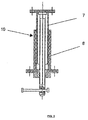
- Figure 2 involves details of the lifting part as a cross-section along its transversal axis.
- Figure 3 shows a view of the casing handling tool as it is working.
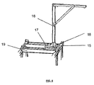
- Figure 4 is a view of the boom mounted on the rail beams.
- Figure 5 is a side view of the wind turbine, where the side wall is cross-sectioned to show the location of the handling tool. The original layout of the casing before lifting and moving is shown by the dotted line.
- Figure 6 is a view of the top of the wind turbine with the casing removed and turned 90°.
- the dotted lines show the original layout and an intermediate step as it turns.
- Figure 7 is a view of the top of the wind turbine with the casing secured by the boom and the turn being made for moving.
- the dotted line shows the casing before it is turned.
- the handling tool consists of padded sheets (1) on which joists (2) with supports (3) on each end are mounted.
- the padded sheets (1) are responsible for pressing the casing and securing it transversally.
- Joists (2) are fitted perpendicular to the sheets, which have adjustable supports (3) on their ends to secure the casing lengthways.
- These two parts comprise the casing securing system and are combined with the lifting mechanism (10) made up of a mechanical or hydraulic jack supported on beams (5) that can move thanks to the wheels (6) fitted on their ends.
- the padded sheets (1) are made up of two cylindrical bars connected to each other by crossbeams (4) that pull out at each end over a surface area that is widest in the intermediate area (11).
- the upper padded sheet (1) has an intermediate area (11) with a pass hole (12) for tool assembly.
- the joists (2) are attached to the padded sheets (1) using a securing system which is easy to mount and dismantle.
- the joists (2) have adjustable supports (3) at the ends that pull out lengthways and end in duly padded support disks (13).
- the lifting mechanism (10) that crosses the base structure made up of a combination of H-shaped beams (5) extends from the lower padded sheet.
- the four free ends of the beams (5) are fitted with wheels (6) and reinforcement strips (14) anchored to the lifting mechanism.
- Figure 2 shows the lifting mechanism (10) made up of two bodies: a top one (7) and a lower one (8) that insert into each other to allow for relative sliding between them.
- This mechanism is fitted with a mechanical or hydraulic jack (4) to lift it and a turning mechanism to pivot the upper body (7), keeping the lower body stable (8).
- Figure 3 shows the handling tool mounted on the rail beams (15) forming the general frame and secured to the nacelle casing (9) that, according to the implementation shown, has a slight step at the top right to avoid discontinuity using the corresponding adjustable supports (3) on the ends of the joists (2).
- the lower and upper sheets are secure using connecting parts (20) from the crossbeams on their ends (4). These connecting parts cross the casing (9) through holes in its surface.
- Figure 4 shows the lifting tool made up of a boom (16) anchored to a combination of H-shaped crossbeams (17), the base of the boom (18) resting on the central crossbeam.
- This combination of beams rests on an overhead crane (19) to enable the assembly to be moved along its longer sides.
- the overhead crane (19) is anchored onto the rail beams (15) forming the nacelle frame.
- the boom (17) can turn on its axis.
- the first stage in removing the cover roof is to fit the aforementioned handling tool onto the rail beams (15).
- the padded sheets (1) are then mounted to press the casing (9) transversally, which are fitted with joists (2) and supports (3) which are adjustable lengthways. Once the casing (9) is secure, it is lifted using the lifting mechanism (10) and moved lengthways thanks to the wheels (6) on the ends of the beams (5) that form the H-shaped base of the tool.
- Figure 6 shows how the handling tool turns the casing (9), leaving it perpendicular to its standby location.
- the lifting and lowering tool (16) which is anchored to the overhead crane (19), is then mounted.
- the crossbeams (17) forming the base of the boom (16) can move lengthways over the overhead crane (19) to allow the casing to be lowered (9) on one side or another, as indicated in Figure 7.
Landscapes
- Engineering & Computer Science (AREA)
- Mechanical Engineering (AREA)
- Life Sciences & Earth Sciences (AREA)
- Sustainable Development (AREA)
- Sustainable Energy (AREA)
- Chemical & Material Sciences (AREA)
- Combustion & Propulsion (AREA)
- General Engineering & Computer Science (AREA)
- Civil Engineering (AREA)
- Structural Engineering (AREA)
- Wind Motors (AREA)
- Lift-Guide Devices, And Elevator Ropes And Cables (AREA)
Applications Claiming Priority (1)
| Application Number | Priority Date | Filing Date | Title |
|---|---|---|---|
| ES200403112A ES2315042B1 (es) | 2004-12-15 | 2004-12-15 | Sistema de retirada de la capota de un aerogenerador. |
Publications (2)
| Publication Number | Publication Date |
|---|---|
| EP1677001A2 true EP1677001A2 (fr) | 2006-07-05 |
| EP1677001A3 EP1677001A3 (fr) | 2012-04-04 |
Family
ID=36306624
Family Applications (1)
| Application Number | Title | Priority Date | Filing Date |
|---|---|---|---|
| EP05381058A Withdrawn EP1677001A3 (fr) | 2004-12-15 | 2005-12-15 | Appareil pour éliminer le toit d'une éolienne |
Country Status (2)
| Country | Link |
|---|---|
| EP (1) | EP1677001A3 (fr) |
| ES (1) | ES2315042B1 (fr) |
Cited By (8)
| Publication number | Priority date | Publication date | Assignee | Title |
|---|---|---|---|---|
| WO2009074859A3 (fr) * | 2007-12-11 | 2009-12-03 | Innovative Windpower Ag | Dispositif de maintenance d'une éolienne |
| WO2009132671A3 (fr) * | 2008-04-30 | 2010-02-25 | Multibrid Gmbh | Habillage de la nacelle d'une éolienne |
| US8601805B2 (en) | 2011-04-05 | 2013-12-10 | Mitsubishi Heavy Industries, Ltd. | Power generating apparatus of renewable energy type |
| WO2013182198A1 (fr) | 2012-06-04 | 2013-12-12 | Liftra Ip Aps | Procédé et moyens d'établissement d'un accès aux principales pièces de la nacelle d'une éolienne |
| WO2018054437A1 (fr) | 2016-09-21 | 2018-03-29 | Vestas Wind Systems A/S | Procédé d'ouverture d'une partie de couvercle d'une éolienne |
| CN110529343A (zh) * | 2019-10-16 | 2019-12-03 | 南京高速齿轮制造有限公司 | 一种风力发电机机舱上罩顶撑装置 |
| US10920752B2 (en) | 2016-12-22 | 2021-02-16 | Vestas Wind Systems A/S | Nacelle for a wind turbine and a wind turbine |
| CN120759721A (zh) * | 2025-08-29 | 2025-10-10 | 江苏常友环保科技股份有限公司 | 一种内置式箱变上移机舱罩 |
Family Cites Families (5)
| Publication number | Priority date | Publication date | Assignee | Title |
|---|---|---|---|---|
| SE466466B (sv) * | 1990-10-04 | 1992-02-17 | Sven Svenning | Anordning vid vindkraftverk |
| DK173530B2 (da) * | 1999-11-17 | 2005-07-18 | Siemens Wind Power As | Fremgangsmåde til montering af hovedkomponenter i kabine på vindmölle og en sådan kabine til vindmölle |
| DE19955516C1 (de) * | 1999-11-18 | 2001-12-20 | Tacke Windenergie Gmbh | Windkraftanlage und Verfahren zum Aus- und Einbau der Hauptkomponenten des Maschinengehäuses einer Windkraftanlage |
| ATE366226T1 (de) * | 2000-10-25 | 2007-07-15 | Nordex Energy Gmbh | Verfahren zum anbringen eines kranes an einer windmühle |
| AU2003239786A1 (en) * | 2002-06-26 | 2004-01-19 | Neg Micon A/S | Frame for a nacelle for a wind turbine and hatch means for a nacelle |
-
2004
- 2004-12-15 ES ES200403112A patent/ES2315042B1/es not_active Expired - Fee Related
-
2005
- 2005-12-15 EP EP05381058A patent/EP1677001A3/fr not_active Withdrawn
Cited By (13)
| Publication number | Priority date | Publication date | Assignee | Title |
|---|---|---|---|---|
| WO2009074859A3 (fr) * | 2007-12-11 | 2009-12-03 | Innovative Windpower Ag | Dispositif de maintenance d'une éolienne |
| WO2009132671A3 (fr) * | 2008-04-30 | 2010-02-25 | Multibrid Gmbh | Habillage de la nacelle d'une éolienne |
| CN102066749B (zh) * | 2008-04-30 | 2013-10-30 | 阿利发风有限公司 | 风能装置的吊舱的护罩 |
| US8601805B2 (en) | 2011-04-05 | 2013-12-10 | Mitsubishi Heavy Industries, Ltd. | Power generating apparatus of renewable energy type |
| WO2013182198A1 (fr) | 2012-06-04 | 2013-12-12 | Liftra Ip Aps | Procédé et moyens d'établissement d'un accès aux principales pièces de la nacelle d'une éolienne |
| US9845791B2 (en) | 2012-06-04 | 2017-12-19 | Liftra Ip Aps | Method and means for establishing access to the main parts in the nacelle on a wind turbine |
| WO2018054437A1 (fr) | 2016-09-21 | 2018-03-29 | Vestas Wind Systems A/S | Procédé d'ouverture d'une partie de couvercle d'une éolienne |
| CN109790826A (zh) * | 2016-09-21 | 2019-05-21 | 维斯塔斯风力系统有限公司 | 用于打开风轮机的盖部分的方法 |
| US10982659B2 (en) | 2016-09-21 | 2021-04-20 | Vestas Wind Systems A/S | Method for opening a cover portion of a wind turbine |
| US10920752B2 (en) | 2016-12-22 | 2021-02-16 | Vestas Wind Systems A/S | Nacelle for a wind turbine and a wind turbine |
| CN110529343A (zh) * | 2019-10-16 | 2019-12-03 | 南京高速齿轮制造有限公司 | 一种风力发电机机舱上罩顶撑装置 |
| CN120759721A (zh) * | 2025-08-29 | 2025-10-10 | 江苏常友环保科技股份有限公司 | 一种内置式箱变上移机舱罩 |
| CN120759721B (zh) * | 2025-08-29 | 2025-11-07 | 江苏常友环保科技股份有限公司 | 一种内置式箱变上移机舱罩 |
Also Published As
| Publication number | Publication date |
|---|---|
| ES2315042B1 (es) | 2010-01-11 |
| ES2315042A1 (es) | 2009-03-16 |
| EP1677001A3 (fr) | 2012-04-04 |
Similar Documents
| Publication | Publication Date | Title |
|---|---|---|
| CN205688927U (zh) | 用于单极子的底座和单极子结构 | |
| KR101756323B1 (ko) | 풍력 발전기용 하이브리드 타워 건설방법 | |
| EP2851328B1 (fr) | Grue télescopique auto-escamotable et procédé de montage de tours préfabriquées en béton | |
| EP3517776B1 (fr) | Méthode et équipement pour le remplacement d'éléments d'éolienne | |
| CN103003509B (zh) | 用于装配风力涡轮机塔架部分的装配设备 | |
| CN102674131A (zh) | 用于从燃气轮机辅助间移除扭矩变换器和启动马达的设备 | |
| EP2746570B1 (fr) | Appareil d'installation et procédé de construction d'une éolienne | |
| JP2004512244A (ja) | 風車にクレーンを置く方法 | |
| KR20140002751A (ko) | 풍력발전용 터빈 타워의 외측 표면에 접근하기 위한 방법 및 상기 방법을 사용하는 장치 | |
| JP2013063767A (ja) | 洋上風力発電の風車設備の設置専用船、設置治具及び設置方法 | |
| JP2020528114A (ja) | 垂直及び略垂直なコンクリート表面用のセルフクライミング装置及び動作方法 | |
| KR20180035717A (ko) | 무거운 하중을 들어올리기 위한 장치 | |
| JP3732414B2 (ja) | 塔状構造物の構築方法およびその装置 | |
| EP1677001A2 (fr) | Appareil pour éliminer le toit d'une éolienne | |
| JP2004308521A (ja) | 風力発電装置の建設方法と建設装置 | |
| JP2002147340A (ja) | 風車発電機の設置方法および風車発電機 | |
| CN106744271A (zh) | 风力发电机叶片吊装工装、吊具及吊装方法和拆卸方法 | |
| CN102674165B (zh) | 从燃气涡轮的辅助隔室移除扭矩变换器和启动马达的方法 | |
| CN111219067B (zh) | 一种建筑施工用卸料平台 | |
| JP5419003B2 (ja) | 貯槽用ジャッキ装置と浮屋根式貯槽の工事施工法 | |
| JP6545965B2 (ja) | クライミングクレーン | |
| CN218658830U (zh) | 一种安拆重型销轴辅助装置 | |
| US4238115A (en) | Jacking device | |
| US9764932B2 (en) | Jacking tower installation system | |
| JPH0878264A (ja) | 変圧器の鉄心起立方法、及びその作業装置 |
Legal Events
| Date | Code | Title | Description |
|---|---|---|---|
| PUAI | Public reference made under article 153(3) epc to a published international application that has entered the european phase |
Free format text: ORIGINAL CODE: 0009012 |
|
| AK | Designated contracting states |
Kind code of ref document: A2 Designated state(s): AT BE BG CH CY CZ DE DK EE ES FI FR GB GR HU IE IS IT LI LT LU LV MC NL PL PT RO SE SI SK TR |
|
| AX | Request for extension of the european patent |
Extension state: AL BA HR MK YU |
|
| RAP1 | Party data changed (applicant data changed or rights of an application transferred) |
Owner name: GAMESA INNOVATION & TECHNOLOGY, S.L. UNIPERSONAL |
|
| PUAL | Search report despatched |
Free format text: ORIGINAL CODE: 0009013 |
|
| AK | Designated contracting states |
Kind code of ref document: A3 Designated state(s): AT BE BG CH CY CZ DE DK EE ES FI FR GB GR HU IE IS IT LI LT LU LV MC NL PL PT RO SE SI SK TR |
|
| AX | Request for extension of the european patent |
Extension state: AL BA HR MK YU |
|
| RIC1 | Information provided on ipc code assigned before grant |
Ipc: F03D 11/04 20060101ALI20120224BHEP Ipc: F03D 1/00 20060101AFI20120224BHEP |
|
| AKY | No designation fees paid | ||
| REG | Reference to a national code |
Ref country code: DE Ref legal event code: R108 |
|
| REG | Reference to a national code |
Ref country code: DE Ref legal event code: R108 Effective date: 20121212 |
|
| STAA | Information on the status of an ep patent application or granted ep patent |
Free format text: STATUS: THE APPLICATION IS DEEMED TO BE WITHDRAWN |
|
| 18D | Application deemed to be withdrawn |
Effective date: 20121005 |