EP1677324A2 - Herstellungsverfahren eines Öffnungsschalters für Türen oder Kofferraum eines Kraftfahrzeuges und einen durch dieses Verfahren erhaltenen Schalter. - Google Patents
Herstellungsverfahren eines Öffnungsschalters für Türen oder Kofferraum eines Kraftfahrzeuges und einen durch dieses Verfahren erhaltenen Schalter. Download PDFInfo
- Publication number
- EP1677324A2 EP1677324A2 EP05112534A EP05112534A EP1677324A2 EP 1677324 A2 EP1677324 A2 EP 1677324A2 EP 05112534 A EP05112534 A EP 05112534A EP 05112534 A EP05112534 A EP 05112534A EP 1677324 A2 EP1677324 A2 EP 1677324A2
- Authority
- EP
- European Patent Office
- Prior art keywords
- microswitch
- tabs
- connection element
- switch
- intermediate body
- Prior art date
- Legal status (The legal status is an assumption and is not a legal conclusion. Google has not performed a legal analysis and makes no representation as to the accuracy of the status listed.)
- Granted
Links
Images






Classifications
-
- E—FIXED CONSTRUCTIONS
- E05—LOCKS; KEYS; WINDOW OR DOOR FITTINGS; SAFES
- E05B—LOCKS; ACCESSORIES THEREFOR; HANDCUFFS
- E05B81/00—Power-actuated vehicle locks
- E05B81/54—Electrical circuits
- E05B81/64—Monitoring or sensing, e.g. by using switches or sensors
- E05B81/76—Detection of handle operation; Detection of a user approaching a handle; Electrical switching actions performed by door handles
-
- H—ELECTRICITY
- H01—ELECTRIC ELEMENTS
- H01H—ELECTRIC SWITCHES; RELAYS; SELECTORS; EMERGENCY PROTECTIVE DEVICES
- H01H11/00—Apparatus or processes specially adapted for the manufacture of electric switches
-
- H—ELECTRICITY
- H01—ELECTRIC ELEMENTS
- H01H—ELECTRIC SWITCHES; RELAYS; SELECTORS; EMERGENCY PROTECTIVE DEVICES
- H01H13/00—Switches having rectilinearly-movable operating part or parts adapted for pushing or pulling in one direction only, e.g. push-button switch
- H01H13/02—Details
- H01H13/04—Cases; Covers
-
- H—ELECTRICITY
- H01—ELECTRIC ELEMENTS
- H01H—ELECTRIC SWITCHES; RELAYS; SELECTORS; EMERGENCY PROTECTIVE DEVICES
- H01H9/00—Details of switching devices, not covered by groups H01H1/00 - H01H7/00
- H01H9/02—Bases, casings, or covers
- H01H2009/0285—Casings overmoulded over assembled switch or relay
-
- H—ELECTRICITY
- H01—ELECTRIC ELEMENTS
- H01H—ELECTRIC SWITCHES; RELAYS; SELECTORS; EMERGENCY PROTECTIVE DEVICES
- H01H11/00—Apparatus or processes specially adapted for the manufacture of electric switches
- H01H2011/0081—Apparatus or processes specially adapted for the manufacture of electric switches using double shot moulding, e.g. for forming elastomeric sealing elements on form stable casing
Definitions
- the present invention refers to an aperture manufacturing method for doors or doors of vehicle trunks, which can operate equally efficiently on the side doors or other areas of the vehicle.
- the invention also refers to a switch obtained by this method, this switch being of manual type to cause the opening of the door lock, after unlocking the lock through the corresponding closure; or remote-type activated with the remote control of opening of the vehicle or system "hands free" recognition of the owner of the vehicle.
- Switches that apply to the rear and side doors of vehicles are known; with their carcass closed inferiorly by a flexible membrane, made of special elastomeric material, and closed above by a lid. When the user presses with the fingers on the flexible membrane it causes the opening of the lock of the lock.
- a lever for operating a microswitch Inside the casing is a lever for operating a microswitch.
- This lever is movable in two positions, a first open position, in which it is separated from said microswitch, and a second closed position, in which it is in contact with said microswitch when the user presses the flexible membrane and it returns to its initial position of rest when the pressure ceases, thanks to elastic means of return.
- the carcass is provided with coupling means with the cover and mounting means on the frame of a side door or a door rear of vehicle.
- the switch may also have a perimeter seal mounted between the cover and the carcass. This structural configuration is adequate when it is necessary to seal the switch against water or moisture from the inside of the vehicle or the hubcap of the switch.
- the plastic material cover is over-molded on the microswitch using a conventional plastic injection machine. According to this method of over-molding the lid, two types of switches are known, depending on the union of the microswitch with the electrical connection elements.
- One type of switch has the microswitch connected to the electrical wiring through a connection element, so that this connection element traps the end of the cable on one side and the other on the other side.
- metal legs of the own microswitch In this case, the cover is overmolded on the assembly formed by the microswitch, the end of the wiring and the connection element.
- switches have the microswitch connected to metal terminals, so that the tabs of the microswitch are firmly soldered to these terminals.
- the terminals perform the macho connector function, and can be coupled to a suitable female connector.
- the cover is overmolded on the assembly formed by the microswitch and the terminals welded thereto.
- the overmolding process of the lid is carried out in a single step of over-injection at high pressure.
- the purpose of the method of manufacturing a switch for doors or doors of vehicle boxes, and the switch obtained by the method of the The present invention is to solve the disadvantages presented by the switches known in the art, by proposing a method ensuring the quality and reliability of the switches.
- step a) The overmolding of step a) will preferably be carried out by a low pressure molding machine, using a high molecular weight, low viscosity polymer, such as a polyamide.
- step a) will optionally be performed with a conventional high pressure injection machine, using a very low pressure, low viscosity and low melting point polymer, such as polystyrene or polypropylene.
- the method is characterized in that prior to step a) the tabs are welded to the connection element and the end of the wiring clips to this connection element.
- the method is characterized by the fact that that before step a) the microswitch tabs and the end of the wiring are respectively stapled to the connection element.
- step a) the overmoulding of step a) is performed on the assembly formed by the microswitch and the connection element.
- the method is characterized in that before step a) the tabs of the microswitch and the end of the wiring are respectively stapled to the connection element.
- step a) the overmoulding of step a) will be performed leaving the ends of the microswitch lugs free.
- step a) the folding of the tabs will be performed at approximately 90 °, these and the connection element being thus housed in a cavity formed in the intermediate body, in order to protect the connection of the energy flow. of the high-pressure over-injection of the second stage.
- step b) the high-pressure overmolding of step b) is performed leaving the wiring and the operating zone of the microswitch free.
- step a) The overmolding of step a) will preferably be carried out using a low pressure molding machine, using a high molecular weight, low viscosity polymer, such as a polyamide.
- step a) The overmolding of step a) will be done optionally using a conventional high-pressure injection machine, using a very low-voltage polymer, low viscosity and low melting temperature, such as polystyrene or polypropylene.
- the method is characterized by the fact that before step a) the tabs are soldered to the connection element .
- the method is characterized by the fact that before step a) the tabs are stapled to the element connection.
- step a) the overmolding of step a) is carried out on the assembly formed by the microswitch and the connection element.
- the method is characterized in that before step a) the tabs are stapled to the connection element.
- step a) the overmoulding of step a) is carried out leaving the ends of the microswitch lugs free.
- step a) the folding of the legs will be at about 90 °, the legs and the connection element remaining housed in a cavity formed in the intermediate body, to protect the connection of the energy flow of the high-pressure over-injection of the second step.
- the method is characterized in that before step a) the tabs are stapled to the connection element.
- step a) the overmoulding of step a) will be performed leaving the ends of the microswitch lugs free.
- step b) the high-pressure overmolding of step b) will be performed leaving the ends of the terminals and the operating zone of the microswitch free.
- the ends of the terminals that assume the function of male connector are likely to mate with a suitable female connector.
- the first molding step is preferably performed using a special injection machine, based on a technology called "low pressure molding", thus obtaining an intermediate body molded at low pressure on the assembly formed by the microswitch.
- low pressure molding a technology that makes it possible to avoid damage to the microswitch during said process.
- the second molding step will be performed using a conventional plastic injection machine, so as to obtain an over-injected coverage on the intermediate body cited obtained beforehand by the low-voltage overmoulding and the electrical connection means (either the wiring with the connection element or with the terminals welded to the microswitch lugs).
- the high-pressure over-injection step is no longer carried out directly on the assembly formed by the microswitch and the electrical connection means as was the conventional method, but it is performed on the intermediate body obtained. thanks to low pressure molding.
- the low pressure molding technology allows a better level of automation of the manufacturing process since there is a simpler handling of the components and therefore, the cost of each switch is lower than that of the conventional switches. .
- the intermediate body obtained is perfectly waterproof.
- the wiring of the switch described in the first method can have an adjusted cable-pass coupled to the chassis of the vehicle to prevent the entry of water or moisture at the end of the connector of the switch.
- the invention also refers to a switch obtained by any of the two methods described above, which comprises a housing housing the microswitch and the means of its actuation, closed on one side with the lid, and the other with a flexible membrane on which a user presses for cause the opening of said switch.
- a first embodiment of the switch 1 for doors or doors of vehicle trunks of the invention is shown in Figures 1 to 3.
- the opening switch 1 has a carcass 2 closed lower by a flexible membrane 3, and closed upperly by a cover 4. Between the carcass 2 and the cover 4 a seal can be placed (not shown). Inside the carcass 2 is a lever 5 for actuating a microswitch 6. This lever 5 is movable to two positions, a first open position, separated from the microswitch 6, and a second closed position (shown in discontinuous line) where it is in contact with the microswitch 6. It also has elastic return means 7 of the lever 5 of this second position to the first.
- the microswitch 6 is connected to an electrical wiring 9 through a connection element 10.
- the microswitch 6 is provided with four short legs 8 of connection, which emerge from the sides of the own microswitch.
- connection element 10 we describe the two variants of the type of union of microswitch 6 to connection element 10 before executing the low-pressure overmolding of step a).
- the tabs 8 are welded to the connection element 10 and the end of the wiring 9 is stapled to this connection element 10.
- step a) the low-pressure overmoulding of step a) is performed on the assembly formed by the microswitch 6 and the connection element 10.
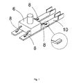
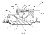
- FIGS. 4 to 6 A second embodiment of the switch 1a of the invention is shown in FIGS. 4 to 6.
- the switch 1a presents the elements according to the references 2,3,4,5,7 and 9 of the first embodiment, and is manufactured according to the same method described in the first embodiment, thus obtaining an intermediate body 12a and a cover 11a.
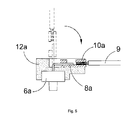
- the difference lies in the fact that the tabs 8a of the microswitch 6a are long and emerge from its upper part (see FIG. 4), arranged, in a position of use in a direction substantially perpendicular to the movement of the actuating means 5, 7 of the microswitch 6a. in this case, the tabs 8a of the microswitch 6a and the end of the wiring 9 are respectively stapled to the connection element 10a (see Figure 5).
- step a) of the process is carried out leaving the ends of the lugs 8a of the microswitch 6a free. Also, after step a), the folding of the tabs 8 a is carried out at about 90 °, as shown in dashed line in Figure 5, the tabs 8a and the connecting member 10a being accommodated in a cavity formed in the intermediate body 12a.
- the high-pressure overmoulding of step b) is carried out leaving the wiring 9 and the coupling zone of the microswitch 6a free.
- the low pressure molded polymer is a high molecular weight, low viscosity polyamide, although other polymers of similar characteristics can be applied.
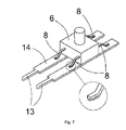
- FIGS. 7 to 9 A third embodiment of the switch 1b of the invention is shown in FIGS. 7 to 9.
- the switch 1b has the same elements by following the references 2 to 7 of the first embodiment.
- microswitch 6 is connected to electrical terminals 13 through a connection element 14, these terminals 13 being integrated in the connection element cited 14.
- the microswitch 6 is provided with four short legs 8 of connection, which emerge from its sides. We next describe two variants of the type of union of microswitch 6 to the connection element 14 before carrying out the low-pressure overmoulding of step a).
- the tabs 8 are welded to the connection element 14.
- the tabs 8 are stapled to the connection element 14.
- step a) the low-pressure overmoulding of step a) is carried out on the assembly formed by the microswitch 6 and the connection element 14.
- FIGS. 10 to 12 A fourth embodiment of the switch 1c of the invention is shown in FIGS. 10 to 12.
- the switch 1c comprises the same elements according to the references 2,3,4,5,7 and 13 of the third embodiment, and is manufactured according to the same method described in the third embodiment, thus obtaining a body intermediate 12c and cover 11c.
- the difference lies in the fact that the tabs 8a of the microswitch 6a are long and emerge from its upper part (see FIG. 10), arranged, in the position of use, in a direction substantially perpendicular to the movement of the actuating means 5 , 7 of the microswitch 6a. In this case, the tabs 8a are stapled to the connection element 14a (see FIG. 11).
- step a) the low-pressure overmoulding of step a) is carried out leaving the ends of the tabs 8a of the microswitch 6a free. furthermore, after step a) folding of the mentioned tabs 8a is performed at about 90 °, as shown in Figure 10 in broken line, the mentioned tabs 8a and the connecting member 14a being housed in a formed cavity in the intermediate body 12c.
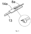
- FIG. 1 A fifth embodiment of the switch 1d of the invention is shown in FIG.
- the switch 1d has the same elements with the references 2,3,4,5,7,6a, 8a, 13 and 14a of the fourth embodiment, and is manufactured according to the same method described in the third and fourth embodiments. , thus obtaining an intermediate body 12d and a cover 11d.
- the tabs 8a are also stapled to the connection element 14a.
- the low-pressure overmolding of step a) is also carried out leaving the ends of the lugs 8a of the microswitch 6a free.
- the high-pressure overmolding of step b) is performed leaving the ends of the terminals 13 and the operating zone of the microswitch 6a free.
- the ends of the terminals 13 which assume the function of macho connector likely to mate on a suitable female connector.
- the low pressure molded polymer is a high weight, low viscosity polyamide, although other polymers of similar characteristics can be applied.
Landscapes
- Engineering & Computer Science (AREA)
- Manufacturing & Machinery (AREA)
- Manufacture Of Switches (AREA)
- Push-Button Switches (AREA)
- Switch Cases, Indication, And Locking (AREA)
- Switches Operated By Changes In Physical Conditions (AREA)
- Lock And Its Accessories (AREA)
Applications Claiming Priority (1)
| Application Number | Priority Date | Filing Date | Title |
|---|---|---|---|
| ES200403097 | 2004-12-28 |
Publications (4)
| Publication Number | Publication Date |
|---|---|
| EP1677324A2 true EP1677324A2 (de) | 2006-07-05 |
| EP1677324A3 EP1677324A3 (de) | 2007-06-27 |
| EP1677324B1 EP1677324B1 (de) | 2008-10-22 |
| EP1677324B2 EP1677324B2 (de) | 2018-03-28 |
Family
ID=36143471
Family Applications (1)
| Application Number | Title | Priority Date | Filing Date |
|---|---|---|---|
| EP05112534.2A Expired - Lifetime EP1677324B2 (de) | 2004-12-28 | 2005-12-20 | Herstellungsverfahren eines Öffnungsschalters für Türen oder Kofferraum eines Kraftfahrzeuges. |
Country Status (3)
| Country | Link |
|---|---|
| EP (1) | EP1677324B2 (de) |
| AT (1) | ATE412246T1 (de) |
| DE (1) | DE602005010537D1 (de) |
Cited By (5)
| Publication number | Priority date | Publication date | Assignee | Title |
|---|---|---|---|---|
| EP2230366A3 (de) * | 2009-03-20 | 2017-01-18 | Gjm, S.A. | Griff für Fahrzeuge |
| CN113228215A (zh) * | 2018-10-25 | 2021-08-06 | 伊利诺斯工具制品有限公司 | 用于车门的信号发生器 |
| DE102022115844B3 (de) | 2022-06-24 | 2023-09-07 | Illinois Tool Works Inc. | Modul zum erzeugen von öffnungssignalen sowie betätigungsmechanismus zum öffnen von fahrzeugtüren und fahrzeug mit betätigungsmechanismus |
| US12368011B2 (en) | 2022-06-24 | 2025-07-22 | Illinois Tool Works Inc. | Module for generating opening signals |
| US12540497B2 (en) | 2022-11-28 | 2026-02-03 | Illinois Tool Works Inc. | Operating mechanism for operating vehicle doors |
Family Cites Families (3)
| Publication number | Priority date | Publication date | Assignee | Title |
|---|---|---|---|---|
| DE1276780B (de) * | 1964-09-11 | 1968-09-05 | Werner Kerber | Druckschalter, insbesondere fuer Fussbetaetigung |
| DE4139091C2 (de) * | 1991-11-28 | 2002-02-07 | Hofsaes Geb Zeitz | Temperaturschalter in einem dichten Gehäuse |
| EP1128405A1 (de) * | 2000-02-21 | 2001-08-29 | Cherry GmbH | Mikroschalterbaueinheit |
-
2005
- 2005-12-20 AT AT05112534T patent/ATE412246T1/de not_active IP Right Cessation
- 2005-12-20 EP EP05112534.2A patent/EP1677324B2/de not_active Expired - Lifetime
- 2005-12-20 DE DE602005010537T patent/DE602005010537D1/de not_active Expired - Lifetime
Cited By (6)
| Publication number | Priority date | Publication date | Assignee | Title |
|---|---|---|---|---|
| EP2230366A3 (de) * | 2009-03-20 | 2017-01-18 | Gjm, S.A. | Griff für Fahrzeuge |
| CN113228215A (zh) * | 2018-10-25 | 2021-08-06 | 伊利诺斯工具制品有限公司 | 用于车门的信号发生器 |
| CN113228215B (zh) * | 2018-10-25 | 2025-01-10 | 伊利诺斯工具制品有限公司 | 用于车门的信号发生器 |
| DE102022115844B3 (de) | 2022-06-24 | 2023-09-07 | Illinois Tool Works Inc. | Modul zum erzeugen von öffnungssignalen sowie betätigungsmechanismus zum öffnen von fahrzeugtüren und fahrzeug mit betätigungsmechanismus |
| US12368011B2 (en) | 2022-06-24 | 2025-07-22 | Illinois Tool Works Inc. | Module for generating opening signals |
| US12540497B2 (en) | 2022-11-28 | 2026-02-03 | Illinois Tool Works Inc. | Operating mechanism for operating vehicle doors |
Also Published As
| Publication number | Publication date |
|---|---|
| EP1677324B1 (de) | 2008-10-22 |
| EP1677324B2 (de) | 2018-03-28 |
| ATE412246T1 (de) | 2008-11-15 |
| EP1677324A3 (de) | 2007-06-27 |
| DE602005010537D1 (de) | 2008-12-04 |
Similar Documents
| Publication | Publication Date | Title |
|---|---|---|
| EP0996180B1 (de) | Knopfzellenträger mit vertikaler Positionierung | |
| EP1677324B1 (de) | Herstellungsverfahren eines Öffnungsschalters für Türen oder Kofferraum eines Kraftfahrzeuges und einen durch dieses Verfahren erhaltenen Schalter. | |
| FR2870636A1 (fr) | Coupe-circuit et cache-bornes | |
| EP0780582A1 (de) | Befestigungs- oder Verschlussvorrichtung mit Überschreitung eines toten Punktes | |
| FR3046903B1 (fr) | Dispositif electronique etanche et son procede d'obtention | |
| WO2011012556A1 (fr) | Commutateur électrique pour portière ou haillon arrière de véhicule automobile | |
| EP1400195A1 (de) | Haushaltsgerät aus scharnierartig verbundenen Rostelementen | |
| FR3002263A3 (fr) | Charniere a interrupteur de securite integre | |
| FR2669897A1 (fr) | Dispositif de verrouillage de deux elements de boitier l'un par rapport a l'autre. | |
| FR2611992A1 (fr) | Agencement de raccordement a vis pour fils et cosses electriques | |
| FR2601513A1 (fr) | Borne de connexion protegee | |
| WO2008068416A2 (fr) | Couvercle a charniere pivotante dotee d' un element de garantie de l'integrite | |
| EP1673672B1 (de) | Steuergriff für ein fahrzeug für öffentliche arbeiten | |
| FR2730772A1 (fr) | Dispositif de fixation reglable de la gaine d'un cable de transmission | |
| EP2259279B1 (de) | Elektrischer Schalter und Herstellungsverfahren dieses Schalters für Hecktür oder Heckklappe eines Kraftfahrzeugs | |
| EP4250325B1 (de) | Elektrischer schalter mit einer elektronischen karte und einem stössel | |
| FR2712619A1 (fr) | Caisson modulaire pour la mise en attente de fers d'armature de béton. | |
| FR2803113A1 (fr) | Module electrique de serrure de vehicule automobile, et procede pour sa fabrication | |
| WO2020089546A1 (fr) | Dispositif et procede de surmoulage d'un vitrage et d'un insert, et insert utilise par lesdits dispositif et procede | |
| FR2784499A1 (fr) | Interrupteur electrique pour atmosphere explosive | |
| EP0520914A1 (de) | Gehäuse für elektrisches Gerät | |
| EP0592295B1 (de) | Dreipoliges Schutzmodul mit Kurzschluss-Schmelzsicherung | |
| FR2584034A1 (fr) | Antivol pour vehicules terrestres a moteur | |
| FR2663360A1 (fr) | Organe de fermeture inviolable pour sac de transport de fonds ou de valeurs, ou objets analogues. | |
| FR2846473A1 (fr) | Element de boitier de connecteur electrique |
Legal Events
| Date | Code | Title | Description |
|---|---|---|---|
| PUAI | Public reference made under article 153(3) epc to a published international application that has entered the european phase |
Free format text: ORIGINAL CODE: 0009012 |
|
| AK | Designated contracting states |
Kind code of ref document: A2 Designated state(s): AT BE BG CH CY CZ DE DK EE ES FI FR GB GR HU IE IS IT LI LT LU LV MC NL PL PT RO SE SI SK TR |
|
| AX | Request for extension of the european patent |
Extension state: AL BA HR MK YU |
|
| PUAL | Search report despatched |
Free format text: ORIGINAL CODE: 0009013 |
|
| AK | Designated contracting states |
Kind code of ref document: A3 Designated state(s): AT BE BG CH CY CZ DE DK EE ES FI FR GB GR HU IE IS IT LI LT LU LV MC NL PL PT RO SE SI SK TR |
|
| AX | Request for extension of the european patent |
Extension state: AL BA HR MK YU |
|
| 17P | Request for examination filed |
Effective date: 20071227 |
|
| AKX | Designation fees paid |
Designated state(s): AT BE BG CH CY CZ DE DK EE ES FI FR GB GR HU IE IS IT LI LT LU LV MC NL PL PT RO SE SI SK TR |
|
| GRAP | Despatch of communication of intention to grant a patent |
Free format text: ORIGINAL CODE: EPIDOSNIGR1 |
|
| GRAS | Grant fee paid |
Free format text: ORIGINAL CODE: EPIDOSNIGR3 |
|
| GRAA | (expected) grant |
Free format text: ORIGINAL CODE: 0009210 |
|
| RIN1 | Information on inventor provided before grant (corrected) |
Inventor name: POMMEL, SYLVAIN Inventor name: VILARDELL, JOAN |
|
| AK | Designated contracting states |
Kind code of ref document: B1 Designated state(s): AT BE BG CH CY CZ DE DK EE ES FI FR GB GR HU IE IS IT LI LT LU LV MC NL PL PT RO SE SI SK TR |
|
| REG | Reference to a national code |
Ref country code: GB Ref legal event code: FG4D Free format text: NOT ENGLISH |
|
| REG | Reference to a national code |
Ref country code: CH Ref legal event code: EP |
|
| REG | Reference to a national code |
Ref country code: IE Ref legal event code: FG4D Free format text: LANGUAGE OF EP DOCUMENT: FRENCH |
|
| REF | Corresponds to: |
Ref document number: 602005010537 Country of ref document: DE Date of ref document: 20081204 Kind code of ref document: P |
|
| NLV1 | Nl: lapsed or annulled due to failure to fulfill the requirements of art. 29p and 29m of the patents act | ||
| PG25 | Lapsed in a contracting state [announced via postgrant information from national office to epo] |
Ref country code: ES Free format text: LAPSE BECAUSE OF FAILURE TO SUBMIT A TRANSLATION OF THE DESCRIPTION OR TO PAY THE FEE WITHIN THE PRESCRIBED TIME-LIMIT Effective date: 20090202 Ref country code: BG Free format text: LAPSE BECAUSE OF FAILURE TO SUBMIT A TRANSLATION OF THE DESCRIPTION OR TO PAY THE FEE WITHIN THE PRESCRIBED TIME-LIMIT Effective date: 20090122 Ref country code: AT Free format text: LAPSE BECAUSE OF FAILURE TO SUBMIT A TRANSLATION OF THE DESCRIPTION OR TO PAY THE FEE WITHIN THE PRESCRIBED TIME-LIMIT Effective date: 20081022 Ref country code: LT Free format text: LAPSE BECAUSE OF FAILURE TO SUBMIT A TRANSLATION OF THE DESCRIPTION OR TO PAY THE FEE WITHIN THE PRESCRIBED TIME-LIMIT Effective date: 20081022 |
|
| PG25 | Lapsed in a contracting state [announced via postgrant information from national office to epo] |
Ref country code: PT Free format text: LAPSE BECAUSE OF FAILURE TO SUBMIT A TRANSLATION OF THE DESCRIPTION OR TO PAY THE FEE WITHIN THE PRESCRIBED TIME-LIMIT Effective date: 20090323 Ref country code: LV Free format text: LAPSE BECAUSE OF FAILURE TO SUBMIT A TRANSLATION OF THE DESCRIPTION OR TO PAY THE FEE WITHIN THE PRESCRIBED TIME-LIMIT Effective date: 20081022 Ref country code: FI Free format text: LAPSE BECAUSE OF FAILURE TO SUBMIT A TRANSLATION OF THE DESCRIPTION OR TO PAY THE FEE WITHIN THE PRESCRIBED TIME-LIMIT Effective date: 20081022 Ref country code: IS Free format text: LAPSE BECAUSE OF FAILURE TO SUBMIT A TRANSLATION OF THE DESCRIPTION OR TO PAY THE FEE WITHIN THE PRESCRIBED TIME-LIMIT Effective date: 20090222 Ref country code: NL Free format text: LAPSE BECAUSE OF FAILURE TO SUBMIT A TRANSLATION OF THE DESCRIPTION OR TO PAY THE FEE WITHIN THE PRESCRIBED TIME-LIMIT Effective date: 20081022 Ref country code: PL Free format text: LAPSE BECAUSE OF FAILURE TO SUBMIT A TRANSLATION OF THE DESCRIPTION OR TO PAY THE FEE WITHIN THE PRESCRIBED TIME-LIMIT Effective date: 20081022 Ref country code: SI Free format text: LAPSE BECAUSE OF FAILURE TO SUBMIT A TRANSLATION OF THE DESCRIPTION OR TO PAY THE FEE WITHIN THE PRESCRIBED TIME-LIMIT Effective date: 20081022 |
|
| BERE | Be: lapsed |
Owner name: VALEO SISTEMAS DE SEGURIDAD Y DE CIERRE, S.A. Effective date: 20081231 |
|
| REG | Reference to a national code |
Ref country code: IE Ref legal event code: FD4D |
|
| PLBI | Opposition filed |
Free format text: ORIGINAL CODE: 0009260 |
|
| PG25 | Lapsed in a contracting state [announced via postgrant information from national office to epo] |
Ref country code: EE Free format text: LAPSE BECAUSE OF FAILURE TO SUBMIT A TRANSLATION OF THE DESCRIPTION OR TO PAY THE FEE WITHIN THE PRESCRIBED TIME-LIMIT Effective date: 20081022 Ref country code: DK Free format text: LAPSE BECAUSE OF FAILURE TO SUBMIT A TRANSLATION OF THE DESCRIPTION OR TO PAY THE FEE WITHIN THE PRESCRIBED TIME-LIMIT Effective date: 20081022 Ref country code: MC Free format text: LAPSE BECAUSE OF NON-PAYMENT OF DUE FEES Effective date: 20081231 Ref country code: IE Free format text: LAPSE BECAUSE OF FAILURE TO SUBMIT A TRANSLATION OF THE DESCRIPTION OR TO PAY THE FEE WITHIN THE PRESCRIBED TIME-LIMIT Effective date: 20081022 Ref country code: RO Free format text: LAPSE BECAUSE OF FAILURE TO SUBMIT A TRANSLATION OF THE DESCRIPTION OR TO PAY THE FEE WITHIN THE PRESCRIBED TIME-LIMIT Effective date: 20081022 |
|
| PLAX | Notice of opposition and request to file observation + time limit sent |
Free format text: ORIGINAL CODE: EPIDOSNOBS2 |
|
| 26 | Opposition filed |
Opponent name: RAFI GMBH & CO. KG RAVENSBURGERSTRASSE 128 - 134 Effective date: 20090717 |
|
| PG25 | Lapsed in a contracting state [announced via postgrant information from national office to epo] |
Ref country code: SE Free format text: LAPSE BECAUSE OF FAILURE TO SUBMIT A TRANSLATION OF THE DESCRIPTION OR TO PAY THE FEE WITHIN THE PRESCRIBED TIME-LIMIT Effective date: 20090122 Ref country code: IT Free format text: LAPSE BECAUSE OF FAILURE TO SUBMIT A TRANSLATION OF THE DESCRIPTION OR TO PAY THE FEE WITHIN THE PRESCRIBED TIME-LIMIT Effective date: 20081022 Ref country code: CZ Free format text: LAPSE BECAUSE OF FAILURE TO SUBMIT A TRANSLATION OF THE DESCRIPTION OR TO PAY THE FEE WITHIN THE PRESCRIBED TIME-LIMIT Effective date: 20081022 |
|
| PG25 | Lapsed in a contracting state [announced via postgrant information from national office to epo] |
Ref country code: BE Free format text: LAPSE BECAUSE OF NON-PAYMENT OF DUE FEES Effective date: 20081231 Ref country code: SK Free format text: LAPSE BECAUSE OF FAILURE TO SUBMIT A TRANSLATION OF THE DESCRIPTION OR TO PAY THE FEE WITHIN THE PRESCRIBED TIME-LIMIT Effective date: 20081022 |
|
| PLAF | Information modified related to communication of a notice of opposition and request to file observations + time limit |
Free format text: ORIGINAL CODE: EPIDOSCOBS2 |
|
| PLBB | Reply of patent proprietor to notice(s) of opposition received |
Free format text: ORIGINAL CODE: EPIDOSNOBS3 |
|
| PG25 | Lapsed in a contracting state [announced via postgrant information from national office to epo] |
Ref country code: CY Free format text: LAPSE BECAUSE OF FAILURE TO SUBMIT A TRANSLATION OF THE DESCRIPTION OR TO PAY THE FEE WITHIN THE PRESCRIBED TIME-LIMIT Effective date: 20081022 Ref country code: HU Free format text: LAPSE BECAUSE OF FAILURE TO SUBMIT A TRANSLATION OF THE DESCRIPTION OR TO PAY THE FEE WITHIN THE PRESCRIBED TIME-LIMIT Effective date: 20090423 Ref country code: LU Free format text: LAPSE BECAUSE OF NON-PAYMENT OF DUE FEES Effective date: 20081220 |
|
| REG | Reference to a national code |
Ref country code: CH Ref legal event code: PL |
|
| PG25 | Lapsed in a contracting state [announced via postgrant information from national office to epo] |
Ref country code: TR Free format text: LAPSE BECAUSE OF FAILURE TO SUBMIT A TRANSLATION OF THE DESCRIPTION OR TO PAY THE FEE WITHIN THE PRESCRIBED TIME-LIMIT Effective date: 20081022 |
|
| PG25 | Lapsed in a contracting state [announced via postgrant information from national office to epo] |
Ref country code: GR Free format text: LAPSE BECAUSE OF FAILURE TO SUBMIT A TRANSLATION OF THE DESCRIPTION OR TO PAY THE FEE WITHIN THE PRESCRIBED TIME-LIMIT Effective date: 20090123 Ref country code: CH Free format text: LAPSE BECAUSE OF NON-PAYMENT OF DUE FEES Effective date: 20091231 Ref country code: LI Free format text: LAPSE BECAUSE OF NON-PAYMENT OF DUE FEES Effective date: 20091231 |
|
| RAP2 | Party data changed (patent owner data changed or rights of a patent transferred) |
Owner name: VALEO CLIMATIZACION S.A. |
|
| APBM | Appeal reference recorded |
Free format text: ORIGINAL CODE: EPIDOSNREFNO |
|
| APBP | Date of receipt of notice of appeal recorded |
Free format text: ORIGINAL CODE: EPIDOSNNOA2O |
|
| APAH | Appeal reference modified |
Free format text: ORIGINAL CODE: EPIDOSCREFNO |
|
| APBQ | Date of receipt of statement of grounds of appeal recorded |
Free format text: ORIGINAL CODE: EPIDOSNNOA3O |
|
| RAP2 | Party data changed (patent owner data changed or rights of a patent transferred) |
Owner name: U-SHIN SPAIN, SL |
|
| APBU | Appeal procedure closed |
Free format text: ORIGINAL CODE: EPIDOSNNOA9O |
|
| PLAY | Examination report in opposition despatched + time limit |
Free format text: ORIGINAL CODE: EPIDOSNORE2 |
|
| PLBC | Reply to examination report in opposition received |
Free format text: ORIGINAL CODE: EPIDOSNORE3 |
|
| PLAH | Information related to despatch of examination report in opposition + time limit modified |
Free format text: ORIGINAL CODE: EPIDOSCORE2 |
|
| PLAT | Information related to reply to examination report in opposition deleted |
Free format text: ORIGINAL CODE: EPIDOSDORE3 |
|
| REG | Reference to a national code |
Ref country code: FR Ref legal event code: PLFP Year of fee payment: 11 |
|
| PLBC | Reply to examination report in opposition received |
Free format text: ORIGINAL CODE: EPIDOSNORE3 |
|
| REG | Reference to a national code |
Ref country code: GB Ref legal event code: 732E Free format text: REGISTERED BETWEEN 20160310 AND 20160316 |
|
| REG | Reference to a national code |
Ref country code: GB Ref legal event code: 732E Free format text: REGISTERED BETWEEN 20160317 AND 20160323 |
|
| REG | Reference to a national code |
Ref country code: FR Ref legal event code: PLFP Year of fee payment: 12 |
|
| REG | Reference to a national code |
Ref country code: FR Ref legal event code: PLFP Year of fee payment: 13 |
|
| PUAH | Patent maintained in amended form |
Free format text: ORIGINAL CODE: 0009272 |
|
| STAA | Information on the status of an ep patent application or granted ep patent |
Free format text: STATUS: PATENT MAINTAINED AS AMENDED |
|
| 27A | Patent maintained in amended form |
Effective date: 20180328 |
|
| AK | Designated contracting states |
Kind code of ref document: B2 Designated state(s): AT BE BG CH CY CZ DE DK EE ES FI FR GB GR HU IE IS IT LI LT LU LV MC NL PL PT RO SE SI SK TR |
|
| REG | Reference to a national code |
Ref country code: DE Ref legal event code: R102 Ref document number: 602005010537 Country of ref document: DE |
|
| REG | Reference to a national code |
Ref country code: DE Ref legal event code: R081 Ref document number: 602005010537 Country of ref document: DE Owner name: U-SHIN SPAIN, SL, ES Free format text: FORMER OWNER: VALEO SISTEMAS DE SEGURIDAD Y DE CIERRE S.A., OLEASA DE MONTSERRAT, ES |
|
| PGFP | Annual fee paid to national office [announced via postgrant information from national office to epo] |
Ref country code: FR Payment date: 20211230 Year of fee payment: 17 Ref country code: GB Payment date: 20211220 Year of fee payment: 17 Ref country code: DE Payment date: 20211210 Year of fee payment: 17 |
|
| REG | Reference to a national code |
Ref country code: DE Ref legal event code: R119 Ref document number: 602005010537 Country of ref document: DE |
|
| GBPC | Gb: european patent ceased through non-payment of renewal fee |
Effective date: 20221220 |
|
| PG25 | Lapsed in a contracting state [announced via postgrant information from national office to epo] |
Ref country code: GB Free format text: LAPSE BECAUSE OF NON-PAYMENT OF DUE FEES Effective date: 20221220 Ref country code: DE Free format text: LAPSE BECAUSE OF NON-PAYMENT OF DUE FEES Effective date: 20230701 |
|
| PG25 | Lapsed in a contracting state [announced via postgrant information from national office to epo] |
Ref country code: FR Free format text: LAPSE BECAUSE OF NON-PAYMENT OF DUE FEES Effective date: 20221231 |