EP1679156B1 - Outil comprenant un cyclone - Google Patents
Outil comprenant un cyclone Download PDFInfo
- Publication number
- EP1679156B1 EP1679156B1 EP05257823A EP05257823A EP1679156B1 EP 1679156 B1 EP1679156 B1 EP 1679156B1 EP 05257823 A EP05257823 A EP 05257823A EP 05257823 A EP05257823 A EP 05257823A EP 1679156 B1 EP1679156 B1 EP 1679156B1
- Authority
- EP
- European Patent Office
- Prior art keywords
- tool
- recovery chamber
- wall
- housing
- cyclone
- Prior art date
- Legal status (The legal status is an assumption and is not a legal conclusion. Google has not performed a legal analysis and makes no representation as to the accuracy of the status listed.)
- Expired - Lifetime
Links
Images


Classifications
-
- B—PERFORMING OPERATIONS; TRANSPORTING
- B23—MACHINE TOOLS; METAL-WORKING NOT OTHERWISE PROVIDED FOR
- B23Q—DETAILS, COMPONENTS, OR ACCESSORIES FOR MACHINE TOOLS, e.g. ARRANGEMENTS FOR COPYING OR CONTROLLING; MACHINE TOOLS IN GENERAL CHARACTERISED BY THE CONSTRUCTION OF PARTICULAR DETAILS OR COMPONENTS; COMBINATIONS OR ASSOCIATIONS OF METAL-WORKING MACHINES, NOT DIRECTED TO A PARTICULAR RESULT
- B23Q11/00—Accessories fitted to machine tools for keeping tools or parts of the machine in good working condition or for cooling work; Safety devices specially combined with or arranged in, or specially adapted for use in connection with, machine tools
- B23Q11/0042—Devices for removing chips
- B23Q11/0046—Devices for removing chips by sucking
-
- B—PERFORMING OPERATIONS; TRANSPORTING
- B24—GRINDING; POLISHING
- B24B—MACHINES, DEVICES, OR PROCESSES FOR GRINDING OR POLISHING; DRESSING OR CONDITIONING OF ABRADING SURFACES; FEEDING OF GRINDING, POLISHING, OR LAPPING AGENTS
- B24B55/00—Safety devices for grinding or polishing machines; Accessories fitted to grinding or polishing machines for keeping tools or parts of the machine in good working condition
- B24B55/06—Dust extraction equipment on grinding or polishing machines
- B24B55/10—Dust extraction equipment on grinding or polishing machines specially designed for portable grinding machines, e.g. hand-guided
-
- Y—GENERAL TAGGING OF NEW TECHNOLOGICAL DEVELOPMENTS; GENERAL TAGGING OF CROSS-SECTIONAL TECHNOLOGIES SPANNING OVER SEVERAL SECTIONS OF THE IPC; TECHNICAL SUBJECTS COVERED BY FORMER USPC CROSS-REFERENCE ART COLLECTIONS [XRACs] AND DIGESTS
- Y02—TECHNOLOGIES OR APPLICATIONS FOR MITIGATION OR ADAPTATION AGAINST CLIMATE CHANGE
- Y02P—CLIMATE CHANGE MITIGATION TECHNOLOGIES IN THE PRODUCTION OR PROCESSING OF GOODS
- Y02P70/00—Climate change mitigation technologies in the production process for final industrial or consumer products
- Y02P70/10—Greenhouse gas [GHG] capture, material saving, heat recovery or other energy efficient measures, e.g. motor control, characterised by manufacturing processes, e.g. for rolling metal or metal working
Definitions
- the present invention relates to a tool for shaping a material which in use generates particulates (eg dust) comprising a cyclone.
- particulates eg dust
- dust which is generated during the operation of a tool may be fine and lightweight and therefore potentially detrimental to health.
- the tool is often combined with a device for preventing the release of dust into the surroundings so that (in particular) the operator is not exposed to excessive amounts of dust while he or she is working.
- fine dust filters are available. However, these filters are very expensive. Electrostatic filters are similarly expensive. In some cases, water has been used as a filtering means. However, such filtering means require permanent supervision and eventual replacement. Moreover it may be difficult to apply such filtering means with an everyday tool or a tool which is used by non-specialists (eg DIY enthusiasts) or which is used in different working positions.
- Cyclones are known to be effective filters for separating dust from a gas. Such cyclones have relatively large dimensions and they are widely used in chemical plants. US-A-4373228 and US-A-4593429 describe the application of a cyclone for separating dust from air in a vacuum cleaner.
- DE-A-19817173 describes the application of a cyclone for separating dust from air in a sander according to the preamble of claim 1.
- the present invention seeks to improve the effectiveness of a tool for shaping a material such as a sander (eg a belt sander, a vibration sander or a rotation sander) which in use generates particulates (eg dust) by deploying cyclonic filtering.
- a tool for shaping a material such as a sander (eg a belt sander, a vibration sander or a rotation sander) which in use generates particulates (eg dust) by deploying cyclonic filtering.
- a tool comprising a cyclone acting as a non-mechanical and non-water based filtering device to substantially prevent the indiscriminate emission of dust during operation.
- a first embodiment of the present invention provides a tool for shaping a material according to claim 1.
- the cyclone advantageously loses no filtration efficiency over a lengthy period and is capable of cleaning a large quantity of air per unit time (eg at high speed) without being excessive large, heavy, expensive or requiring frequent service or maintenance.
- the cyclone is a very effective filter irrespective of whether it is comparable in size to the housing or smaller.
- the particulate filtrate eg dust
- the particulate filtrate may be easily and safely disposed of.
- the tool of the invention is typically a hand-held tool.
- the tool may be a cutting, shaving, sanding or abrading tool.
- the tool is typically a sanding tool which may be used for sanding from above (eg for sanding a floor), from below (eg for sanding a ceiling) or for sanding a vertical surface (eg a wall such as a wall in a room).
- the sanding tool may be a belt sander, a vibration sander or a rotation sander.
- the sander may be employed for domestic or professional purposes.
- the particulates may be shavings, powder or dust.
- the housing may have a handle which may be provided with a power cable and a power switch for controlling an electric motor.
- the electric motor may be arranged on a central axis within the upper part of the housing and typically has a rotary shaft extending along the central axis for driving a sanding plate or pad located outside the base of the housing.
- the outer surface of the pad typically holds a replaceable sanding paper which is applied to a work piece (such as a piece of wood) which causes dust to be generated.
- the base of the housing may be fully or partially open.
- the particulate recovery chamber and/or the cyclone may be attached directly to the housing to achieve a compact tool.
- a fan may be positioned within the housing.
- the fan may be adapted to cause material particulates to be pneumatically discharged through the outlet.
- the tool further comprises:
- the tool further comprises:
- the housing contains a first (eg lower) interior cavity and a second (eg upper) interior cavity, wherein the first interior cavity is separate from the second interior cavity.
- the first and second interior cavity may be separated from each other by a main partition wall.
- Several cooling air inlets may be provided in the upper portion of the second interior cavity, preferably on a top wall of the housing.
- the tool further comprises:
- the housing includes an auxiliary partition wall between the transportation fan and the outlet.
- the housing includes a guiding wall (eg an annular guiding wall) beneath the transportation fan.
- the tool further comprises:
- the particulate recovery chamber may be sealable.
- the particulate recovery chamber has a wall (preferably a door) constituting or containing a sealable particulate recovery port.
- the particulate recovery chamber is substantially cuboidal. It is constructionally straightforward for the particulate recovery chamber to be substantially cuboidal.
- the particulate recovery chamber may have for example a cylindrical configuration or a rectangular or trapezoidal shape.
- the particulate recovery chamber has an essentially trapezoidal shape.
- An essentially trapezoidal shape may be useful to obtain a very compact structure.
- the particulate recovery chamber has a proximal wall, a distal wall and at least one (preferably more than one, particularly preferably four) side wall, wherein the cyclone is attached internally to the proximal wall or the distal wall.
- the side walls may include a base wall and an upper wall.
- the proximal wall may be attached directly to the housing.
- the distal wall may incorporate the air vent and any number of additional air vents. The (or each) air vent may be flush with the distal wall.
- the cyclone is attached internally to the proximal wall and the distal wall is pivotal on a hinge. This enables the distal wall to be used as a particulate recovery port through which recovered material particulates may be removed from time to time.
- the elongate body of the cyclone typically takes the form of a housing having a cylindrical body portion.
- the cylindrical body portion may be mounted internally on the distal wall so as to be descendant in a proximal direction.
- the cyclone may contain a central tube which may extend beyond the distal wall.
- the cylindrical body portion may extend proximally into a conical nose.
- the conical nose terminates in the outlet port.
- the inlet port is typically a tangential inlet port on the cylindrical body portion.
- the cyclone is wholly located inside the particulate recovery chamber. This advantageously achieves a compact design.
- the particulate recovery chamber has a plurality of corners, wherein the cyclone is located in or through one of the corners.
- the cyclone has a first longitudinal axis and the particulate recovery chamber is elongate and has a second longitudinal axis, wherein the first longitudinal axis is substantially parallel (eg parallel or inclined to a small degree) to the second longitudinal axis.
- the first and second longitudinal axis are descendant in a proximal direction.
- the tool typically has a handle which is arranged on the upper part of the housing.
- the tool further comprises:
- the mass of the cyclone and/or the particulate recovery chamber should be minimised. This can be achieved if the material of the cyclone and/or the particulate recovery chamber is a thin metal or plastic. This also keeps costs down. It has been found that such a cyclone is not very sensitive to shocks or touches caused by the operator and therefore may have a long lifetime without losing its effectiveness. In a preferred embodiment, the material of either or both of the cyclone and the particulate recovery chamber is plastic.
- the tool may comprise a plurality (eg two or three) cyclones.
- the number of cyclones is generally dependent on the flow of air that has to be cleaned.
- the tool comprises at least two cyclones which are juxtaposed, particularly preferably juxtaposed within the particulate recovery chamber.
- the cyclone and the particulate recovery chamber may form a self-contained unit which is attached to the housing.
- the unit may be detachable (eg for the purposes of maintenance, service or cleaning) from the housing.
- the particulate recovery chamber may be emptied from time to time by the operator.
- the inlet port may be detachably coupled to the outlet.
- the tool further comprises:
- the air vent communicates directly with the surroundings.
- the tool further comprises: an auxiliary filter mounted across the air vent for capturing minute material particulates.
- the base wall of the particulate recovery chamber is arranged above or level with the base of the housing.
- the tool of the invention may be deployed upside down (when sanding a ceiling) or in a vertical position (when sanding a vertical wall) or in other positions.
- the particulate recovery chamber may be rotatable about its axis.
- the present invention provides a tool for shaping a material comprising:
- Figs 1 to 3 illustrate a first embodiment of a tool 2 of the invention being a random orbital sander comprising a housing 4.
- the housing 4 On its upper portion, the housing 4 has a handle 6 which is provided with a power cable 8 and a power switch 10 for controlling an electric motor 12.
- the electric motor 12 is arranged on a central axis 14 within the upper part of the housing 4 and has a rotary shaft 15 extending along the central axis 14 for driving a sanding plate or pad 16 located outside the base of the housing 4.
- the outer surface of the pad 16 holds a replaceable sanding paper 18.
- the sanding paper 18 is applied to a work piece (such as a piece of wood) which causes dust (denoted by the letter d) to be generated.
- a certain separation between the base of the housing 4 and the pad 16 is maintained.
- a horizontal main partition wall 24 is arranged within the housing 4.
- the main partition wall 24 defines a lower interior cavity 26 and an upper interior cavity 28.
- the lower interior cavity 26 contains a transportation fan 30 fixed on the rotary shaft 15 for pneumatically driving air (a) and dust (d) towards an outlet 32 from which it is discharged.
- the outlet 32 extends into an attachment tube which is located beneath the handle 6.
- the upper interior cavity 28 contains the motor 12 and a cooling fan 34.
- the cooling fan 34 is fixed on the rotary shaft 15 and cools the motor 12 during operation.
- Several cooling air inlets 36 are provided on the top wall of the housing 4 and several cooling air outlets 38 are provided around the lower portion of the upper interior cavity 28.
- the dust recovery chamber 40 accumulates dust (d) by the action of a cyclone 42.
- the dust recovery chamber 40 and the cyclone 42 may be plastic in order to be relatively lightweight.
- the cyclone 40 has a central or first longitudinal axis 70 and the dust recovery chamber 40 has a second longitudinal axis 72.
- the second longitudinal axis 72 and first longitudinal axis 70 are offset.
- the second longitudinal axis 72 is inclined slightly relative to the first longitudinal axis 70.
- the dust recovery chamber 40 has a very compact essentially trapezoidal cross-section comprising a proximal wall 44, a distal wall 46, an upper wall 48, a base wall 54 and side walls 50, 52.
- the second longitudinal axis 72 and first longitudinal axis 70 are descendant in a direction away from the distal wall 46.
- the lower portion of the distal wall 46 constitutes a door 55 pivotal about a hinge 56.
- the door 55 may be opened to remove dust (d) recovered in the dust recovery chamber 40.
- a lock 58 retains the door 55 in a sealed and locked position during operation.
- the cyclone 42 is in the form of a housing having a descendant cylindrical body portion mounted internally on the distal wall 46 and containing a central tube 59.
- the cylindrical body portion has a tangential inlet port 60 and extends proximally into a conical nose.
- the inlet port 60 is coupled to the outlet 32 via a plastic tube 62 mounted on the inner surface of the upper wall 48.
- the conical nose terminates in an outlet port 64 positioned in the central region of the interior of the dust recovery chamber 40.
- the dust (d) descends the cyclone 42 and is conveyed by the outlet port 64 into a pile 66 on the base wall 54.
- the cyclone 42 has an air vent 68 arranged flush with the distal wall 46 for expelling clean air directly into the surrounding.
- Fig. 4 is a cross-sectional side view of an alternative dust recovery chamber 40 containing twin cyclones 42a, 42b arranged adjacent and parallel to each other and mounted on the distal wall 46.
- the respective inlet ports 60a, 60b are coupled to the outlet 32 by a centrally mounted tube 74.
- the respective outlet ports 64a, 64b are located within the interior of the dust recovery chamber 40.
- the respective air vents 68a, 68b are arranged flush with the distal wall 46.
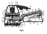
- Fig. 5 is a cross-sectional side view of a sanding tool 2 according to a second embodiment of the invention comprising a housing 4.
- air (a) and dust (d) are pneumatically driven into the cyclone 42 by the positive action of the transportation fan 30, air a and dust d in this embodiment are caused to be pneumatically discharged into the cyclone 42 by a sucking action.
- a main partition wall 24 in the housing 4 defines a lower interior cavity 26 and an upper interior cavity 28.
- a transportation fan 30 is located within the first interior cavity 26 and is adapted to transport clean air (a) into the surroundings via release outlets 78 distributed around the circumference of the housing 4.
- An electric motor 12 and a cooling fan 34 are located within the second interior cavity 28. The electric motor 12 drives the fans 30, 34 and the pad 16 bearing the sanding paper 18 by means of a rotary shaft 15.
- the base of the housing 4 is fully open for transmitting air (a) and dust (d) from a work piece via the holes 20 into an essentially cylindrical cavity 80.
- This cavity 80 is bound by the upper surface of the pad 16, by the side wall(s) of the housing 4 and by an auxiliary partition wall 84 which is parallel to and beneath the main partition wall 24.
- a side wall of the cavity 80 there is an outlet 32.
- a block-shaped dust recovery chamber 40 containing a cyclone 42 is firmly connected to the side of the housing 4. Air (a) and dust (d) are conveyed to the inlet 60 by a tube 62 mounted on the inner surface of the upper wall 48.
- the air vent 68 communicates indirectly with the surroundings via an air return tube 82 which couples the air vent 68 and an entrance to the lower interior cavity 26.
- the air transportation fan 30 sucks clean air a from the cyclone 42 and pneumatically discharges the clean air a through the outlets 78 into the surroundings.
- a guiding wall 86 having a large central opening is positioned between the auxiliary partition wall 84 and the transportation fan 30.
- a discrete cooling fan 34 may be unnecessary if the transportation fan 30 is also used for cooling the motor 12.
- Fig 6 is a cross-sectional side view of a sanding tool 2 according to a third embodiment of the invention where the major portion of a cyclone 42 is located outside a dust recovery chamber 40.
- the dust recovery chamber 40 is block-shaped and has a plurality of corners 88.
- the cyclone 42 is disposed through an open one of the upper corners 88.
- the conical nose of the cyclone 42 extends into the interior of the dust recovery chamber 40 in such a way that the outlet port 64 is located In the middle section of the dust recovery chamber 40.
- the lower portion of the distal wall 46 of the dust recovery chamber 40 forms a door 55 for removing recovered dust d.
- the door 55 is pivotal on a hinge 56 when a lock 58 is released.
- an external tube 62 couples the outlet 32 to the tangential inlet 60 of the cyclone 42.
- the air vent 68 is at the end of the central tube 59.
- the dust recovery chamber 40 and the cyclone 42 form a unit which during operation is firmly attached to the housing 4.
- the unit may be detachable for the purpose of maintenance, service or cleaning.
- Fastening means (not shown) such as bolts and screws are provided.
- Fig. 7 is a cross-sectional side view of a sanding tool according to a fourth embodiment of the invention which is constructed in a very compact manner.
- the housing 4 and the internal elements are the same as in Figs. 1 to 3 and 5.
- Air a and dust d are discharged from an outlet 32 into an upwardly curved tube 62 which passes through the proximal wall 44 and couples the outlet 32 and the inlet port 60.
- the dust recovery chamber 40 has a rectangular cross-section. Its bottom wall 54 is parallel to the pad 16. The entire distal wall forms a door 55 which is pivotal on a hinge 56.
- the cyclone 42 is attached to the proximal wall 44.
- the cylindrical portion of the cyclone 42 is attached to the upper corner area. Cleaned air a will be released into the space between the housing 4 and the chamber 40.
- the longitudinal axes 70, 72 are parallel to each other.
- This embodiment works very well in the horizontal orientation as illustrated. It does not have to be inclined in order to facilitate the emission of dust d from the outlet port 64.
- This embodiment may be used for sanding a floor, a ceiling or a vertical wall.
Landscapes
- Engineering & Computer Science (AREA)
- Mechanical Engineering (AREA)
- Cyclones (AREA)
- Grinding-Machine Dressing And Accessory Apparatuses (AREA)
- Finish Polishing, Edge Sharpening, And Grinding By Specific Grinding Devices (AREA)
Claims (23)
- Outil (2) de mise en forme d'un matériau comprenant :un logement (4) conçu à l'extérieur pour enlever des particules de matière (d) du matériau ;une sortie (32) dans le logement (4) à travers laquelle les particules de matière (d) sont évacuées de manière pneumatique lors de l'utilisation ;une chambre de récupération des particules (40) présentant une paroi (54) constituant ou contenant un orifice de récupération des particules (55) pouvant être fermé hermétiquement ; etau moins un cyclone (42) situé à l'intérieur de la chambre de récupération des particules (40) comportantcaractérisé en ce que le cyclone (42) présente un premier axe longitudinal (70) et la chambre de récupération des particules (40) est allongée et présente un deuxième axe longitudinal (72), le premier axe longitudinal (70) étant sensiblement parallèle au deuxième axe longitudinal (72).un corps allongé présentant une première et une deuxième extrémités,un orifice d'entrée (60) au niveau de la première extrémité du corps allongé ou à proximité de celle-ci, l'orifice d'entrée (60) étant couplé à la sortie (32),un orifice de sortie (64) au niveau d'une deuxième extrémité du corps allongé ou à proximité de celle-ci, conçu pour acheminer les particules de matière (d) dans la chambre de récupération des particules (40) etune bouche d'air (68) servant à expulser l'air du corps allongé,
- Outil (2) selon la revendication 1, comprenant en outre :un ventilateur (30) agencé à l'intérieur du logement (4) de manière à entraîner l'air (a) et les particules de matière (d) par l'orifice de sortie (32).
- Outil (2) selon l'une quelconque des revendications 1 ou 2, comprenant en outre :un ventilateur (30) agencé à l'intérieur du logement (4) de sorte à aspirer l'air (a) de la bouche d'air (68) et entraîner l'évacuation pneumatique des particules de matière de l'orifice de sortie (32).
- Outil (2) selon l'une quelconque des revendications précédentes, dans lequel la chambre de récupération des particules (40) est sensiblement cubique.
- Outil (2) selon la revendication 1, dans lequel la chambre de récupération des particules (40) présente une pluralité de coins (88) et dans lequel le cyclone (42) est agencé dans ou à travers un des coins (88).
- Outil (2) selon l'une quelconque des revendications précédentes, comprenant en outre :une poignée (6) montée à l'extérieur du logement (4), soit le cyclone (42) ou la chambre de récupération des particules (40) soit les deux sont disposés sous la poignée (6).
- Outil (2) selon l'une quelconque des revendications précédentes, dans lequel soit le cyclone (42) ou la chambre de récupération des particules (40) soit les deux sont en plastique.
- Outil (2) selon l'une quelconque des revendications précédentes, comprenant au moins deux cyclones (42a, 42b) juxtaposés.
- Outil (2) selon l'une quelconque des revendications précédentes, dans lequel le cyclone (42) et la chambre de récupération des particules (40) forment une unité qui est fixée au logement (4).
- Outil (2) selon l'une quelconque des revendications précédentes, dans lequel la chambre de récupération des particules (40) présente une section transversale sensiblement trapézoïdale.
- Outil (2) selon l'une quelconque des revendications précédentes, dans lequel la chambre de récupération des particules (40) présente une paroi proximale (44), une paroi distale (46) et au moins une paroi latérale (48, 50, 52, 54) et dans lequel le cyclone (42) est fixé à la paroi distale (46).
- Outil (2) selon la revendication 11, dans lequel la paroi proximale (44) est fixée au logement (4) et dans lequel la paroi distale (46) intègre la bouche d'air (68).
- Outil (2) selon l'une quelconque des revendications précédentes, comprenant en outre :un tube (62) permettant de coupler l'orifice de sortie (32) à l'orifice d'entrée (60).
- Outil (2) selon la revendication 14, dans lequel la chambre de récupération des particules (40) présente au moins une paroi (44, 48, 54) et dans lequel le tube (62) est monté sur une surface intérieure de la paroi (44, 48, 54).
- Outil (2) selon l'une quelconque des revendications précédentes, dans lequel la bouche d'air (68) communique directement avec l'environnement (40).
- Outil (2) selon l'une quelconque des revendications précédentes, dans lequel le logement (4) contient une première cavité intérieure (26) et une deuxième cavité intérieure (28), la première cavité intérieure (26) étant séparée de la deuxième cavité intérieure (28).
- Outil (2) selon la revendication 16, comprenant en outre :un ventilateur de transport (30) placé dans la première cavité intérieure (26) et un ventilateur de refroidissement (34) et un moteur électrique (12) placés dans la deuxième cavité intérieure (28).
- Outil (2) selon la revendication 17, comprenant en outre :un tube de retour d'air (82) couplant la bouche d'air (68) et la première cavité intérieure (26), le ventilateur de transport (30) étant un ventilateur de transport d'air.
- Outil (2) selon la revendication 18, dans lequel le tube de retour d'air (82) est monté à l'extérieur de la chambre de récupération des particules (40).
- Outil (2) selon l'une quelconque des revendications 1 à 10 et 13 à 19, dans lequel la chambre de récupération des particules (40) présente une paroi proximale (44), une paroi distale (46) et au moins une paroi latérale (48, 50, 52, 54) et dans lequel le cyclone (42) est fixé à la paroi proximale (44).
- Outil (2) selon la revendication 20, dans lequel la chambre de récupération des particules (40) présente une section transversale rectangulaire.
- Outil (2) selon l'une quelconque des revendications précédentes, dans lequel une paroi de base (54) de la chambre de récupération des particules (40) est agencée à un niveau supérieur ou égal à la base du logement (4).
- Outil (2) selon l'une quelconque des revendications précédentes étant une sablière, de préférence une sablière électrique.
Applications Claiming Priority (1)
| Application Number | Priority Date | Filing Date | Title |
|---|---|---|---|
| GBGB0500469.2A GB0500469D0 (en) | 2005-01-11 | 2005-01-11 | Tool |
Publications (2)
| Publication Number | Publication Date |
|---|---|
| EP1679156A1 EP1679156A1 (fr) | 2006-07-12 |
| EP1679156B1 true EP1679156B1 (fr) | 2008-04-09 |
Family
ID=34203883
Family Applications (1)
| Application Number | Title | Priority Date | Filing Date |
|---|---|---|---|
| EP05257823A Expired - Lifetime EP1679156B1 (fr) | 2005-01-11 | 2005-12-19 | Outil comprenant un cyclone |
Country Status (5)
| Country | Link |
|---|---|
| US (1) | US7611556B2 (fr) |
| EP (1) | EP1679156B1 (fr) |
| CN (1) | CN1803397B (fr) |
| DE (1) | DE602005005931T2 (fr) |
| GB (1) | GB0500469D0 (fr) |
Cited By (1)
| Publication number | Priority date | Publication date | Assignee | Title |
|---|---|---|---|---|
| US11510534B2 (en) | 2018-01-19 | 2022-11-29 | Black & Decker Inc. | Docking station |
Families Citing this family (35)
| Publication number | Priority date | Publication date | Assignee | Title |
|---|---|---|---|---|
| DE202006002330U1 (de) * | 2006-02-13 | 2007-06-21 | Dolmar Gmbh | Absaugvorrichtung |
| CN103213106B (zh) * | 2007-01-19 | 2015-12-09 | 苏州宝时得电动工具有限公司 | 手持电动工具 |
| US7662199B2 (en) * | 2007-03-07 | 2010-02-16 | Tennant Company | Cyclonic filter for surface maintenance machine |
| DE102009029111B4 (de) | 2009-09-02 | 2021-07-29 | Robert Bosch Gmbh | Handwerkzeugmaschine |
| DE102009054970A1 (de) * | 2009-12-18 | 2011-06-22 | Hilti Aktiengesellschaft | Staubabsaugeinrichtung |
| US20110278907A1 (en) * | 2010-05-12 | 2011-11-17 | Diamond Products, Limited | Concrete Profiler With Vacuum System |
| JP2012061575A (ja) * | 2010-09-17 | 2012-03-29 | Makita Corp | 電動工具の集塵機構 |
| JP2012149635A (ja) | 2010-12-27 | 2012-08-09 | Hitachi Koki Co Ltd | エンジン作業機 |
| CN102601712A (zh) * | 2011-01-19 | 2012-07-25 | 日立工机株式会社 | 集尘适配器与包括集尘适配器的电动工具 |
| CN103813884B (zh) * | 2011-09-20 | 2017-03-15 | 罗伯特·博世有限公司 | 用于柔性磨削器件的保持体、磨削系统和磨削设备 |
| US9393658B2 (en) | 2012-06-14 | 2016-07-19 | Black & Decker Inc. | Portable power tool |
| CN103567841B (zh) * | 2012-08-07 | 2016-09-14 | 苏州宝时得电动工具有限公司 | 磨削动力工具 |
| CN103862351B (zh) * | 2012-12-13 | 2017-06-16 | 苏州宝时得电动工具有限公司 | 偏心旋转摆动类工具 |
| DE102013202673A1 (de) * | 2013-02-19 | 2014-08-21 | Robert Bosch Gmbh | Handwerkzeugmaschinenvorrichtung |
| DE102013215821A1 (de) | 2013-08-09 | 2015-02-12 | Robert Bosch Gmbh | Handwerkzeugmaschine mit einem elektromotorischen Antrieb als Direktantrieb |
| DE102014202218A1 (de) | 2014-02-06 | 2015-08-06 | Robert Bosch Gmbh | Handwerkzeugmaschine mit einem elektronisch kommutierten Elektromotor |
| EP2946887B1 (fr) | 2014-05-20 | 2017-08-23 | Black & Decker Inc. | Ensemble de séparation de particules pour un outil électrique |
| DE102014224570A1 (de) * | 2014-12-02 | 2016-06-02 | Robert Bosch Gmbh | Schutzvorrichtung für eine Werkzeugmaschine, zumindest zu einem Schutz einer Werkstückoberfläche vor einer Überhitzung |
| DE102015121305A1 (de) * | 2015-12-08 | 2017-06-08 | Festool Gmbh | Hand-Werkzeugmaschine |
| CN106926202A (zh) * | 2015-12-30 | 2017-07-07 | 博世电动工具(中国)有限公司 | 吸尘组件及具有该吸尘组件的电动工具 |
| CN106239322B (zh) * | 2016-08-31 | 2018-09-14 | 嘉兴恒源安全技术有限公司 | 一种水利施工用便携式防水打磨装置 |
| CN108436848B (zh) * | 2017-02-16 | 2024-02-27 | 博世电动工具(中国)有限公司 | 空气预清洁组件及具有其的电动工具 |
| CN207509161U (zh) * | 2017-04-01 | 2018-06-19 | 南京德朔实业有限公司 | 集尘装置和电动工具 |
| SE541077C2 (en) * | 2017-09-05 | 2019-03-26 | Husqvarna Ab | Separator, separator system and methods of their operation |
| SE541282C3 (en) * | 2017-09-05 | 2019-07-16 | Husqvarna Ab | Separator and method of operating a separator |
| US11980334B2 (en) | 2017-09-15 | 2024-05-14 | Omachron Intellectual Property Inc. | Surface cleaning apparatus |
| KR102583118B1 (ko) * | 2018-10-22 | 2023-09-25 | 오마크론 인텔렉튜얼 프로퍼티 아이엔씨. | 공기 처리 장치 |
| DE102019209325A1 (de) * | 2019-06-27 | 2020-12-31 | Robert Bosch Gmbh | Akkupack |
| CN212635318U (zh) * | 2019-10-25 | 2021-03-02 | 南京德朔实业有限公司 | 角磨 |
| CN115551678A (zh) * | 2020-05-12 | 2022-12-30 | 工机控股株式会社 | 辅助装置及作业机械系统 |
| CN113927427B (zh) * | 2020-06-29 | 2023-05-26 | 南京泉峰科技有限公司 | 一种旋风集尘装置及打磨装置 |
| EP3932277B1 (fr) * | 2020-06-29 | 2022-09-14 | Nanjing Chervon Industry Co., Ltd. | Dispositif de collecte de poussière à cyclone et dispositif de broyage |
| GB2597957A (en) * | 2020-08-11 | 2022-02-16 | Evolution Power Tools Ltd | Improvements in and to power tools |
| JP7664097B2 (ja) * | 2021-06-17 | 2025-04-17 | 株式会社マキタ | 金工用集塵アタッチメント及び研削工具 |
| CN118305133A (zh) * | 2024-05-13 | 2024-07-09 | 沂水慧阳制衣有限公司 | 一种纺织加工除尘设备 |
Family Cites Families (21)
| Publication number | Priority date | Publication date | Assignee | Title |
|---|---|---|---|---|
| CA980144A (en) | 1972-03-30 | 1975-12-23 | Cominco Ltd. | Rock sampling tool |
| US4201256A (en) * | 1979-01-10 | 1980-05-06 | Andrew Truhan | Sawdust collector |
| US4373228A (en) | 1979-04-19 | 1983-02-15 | James Dyson | Vacuum cleaning appliances |
| FR2545749B2 (fr) | 1980-04-02 | 1987-01-02 | Saillard Louis | Procede et dispositif de captation des poussieres pour touret a meuler |
| US4593429A (en) | 1980-06-19 | 1986-06-10 | Prototypes, Ltd. | Vacuum cleaning appliance |
| US4967516A (en) * | 1989-12-13 | 1990-11-06 | Ryobi Motor Products Corp. | Debris collection system for a surface treating tool |
| CN2100279U (zh) * | 1991-06-24 | 1992-04-01 | 苏志奎 | 无尘电动磨光机 |
| DE4204789C2 (de) | 1992-02-18 | 1994-11-03 | Laegler Eugen Gmbh | Vorrichtung zum Entfernen von Staub aus einer an einer Werkstückbearbeitungsmaschine abgesaugten Staubluft |
| CN2186631Y (zh) * | 1994-01-17 | 1995-01-04 | 常州市电动工具厂 | 自吸式平板砂光机 |
| JPH10277907A (ja) * | 1997-04-08 | 1998-10-20 | Tsuboman:Kk | ディスクグラインダー用集塵アダプター |
| DE19827173A1 (de) * | 1998-06-18 | 1999-12-23 | Bosch Gmbh Robert | Absaugvorrichtung für eine Handwerkzeugmaschine |
| US6238451B1 (en) * | 1999-01-08 | 2001-05-29 | Fantom Technologies Inc. | Vacuum cleaner |
| DE19924547A1 (de) * | 1999-05-28 | 2000-11-30 | Bosch Gmbh Robert | Handwerkzeugmaschine mit Staubabsaugung |
| JP3697698B2 (ja) | 2002-09-18 | 2005-09-21 | いよ技研株式会社 | 集塵装置 |
| US6833016B2 (en) * | 2003-03-27 | 2004-12-21 | Oneida Air Systems, Inc | Dust collection system |
| DE10322641B4 (de) * | 2003-05-20 | 2016-02-04 | Andreas Stihl Ag & Co. Kg | Handgeführtes Arbeitsgerät mit einem Tankgehäuse und einer Entlüftungseinrichtung |
| DE10358030A1 (de) * | 2003-12-11 | 2005-07-07 | Hilti Ag | Zyklonabscheider |
| ES2298670T3 (es) * | 2004-11-19 | 2008-05-16 | Black & Decker Inc. | Extraccion de polvo para herramientas motorizadas. |
| DE102004056856A1 (de) * | 2004-11-25 | 2006-06-01 | Hilti Ag | Grobabscheider |
| US7282074B1 (en) * | 2006-04-28 | 2007-10-16 | Witter Robert M | Auxiliary dust collection system |
| US7550021B2 (en) * | 2006-07-19 | 2009-06-23 | Witter Robert M | Portable cyclonic dust collection system |
-
2005
- 2005-01-11 GB GBGB0500469.2A patent/GB0500469D0/en not_active Ceased
- 2005-12-19 DE DE602005005931T patent/DE602005005931T2/de not_active Expired - Lifetime
- 2005-12-19 EP EP05257823A patent/EP1679156B1/fr not_active Expired - Lifetime
- 2005-12-28 CN CN200510137982XA patent/CN1803397B/zh not_active Expired - Lifetime
-
2006
- 2006-01-06 US US11/327,142 patent/US7611556B2/en not_active Expired - Fee Related
Cited By (1)
| Publication number | Priority date | Publication date | Assignee | Title |
|---|---|---|---|---|
| US11510534B2 (en) | 2018-01-19 | 2022-11-29 | Black & Decker Inc. | Docking station |
Also Published As
| Publication number | Publication date |
|---|---|
| DE602005005931D1 (de) | 2008-05-21 |
| CN1803397A (zh) | 2006-07-19 |
| US7611556B2 (en) | 2009-11-03 |
| US20060150591A1 (en) | 2006-07-13 |
| EP1679156A1 (fr) | 2006-07-12 |
| GB0500469D0 (en) | 2005-02-16 |
| DE602005005931T2 (de) | 2009-05-28 |
| CN1803397B (zh) | 2010-08-11 |
Similar Documents
| Publication | Publication Date | Title |
|---|---|---|
| EP1679156B1 (fr) | Outil comprenant un cyclone | |
| CA2517944C (fr) | Aspiration de poussiere d'outils electriques | |
| JP3448110B2 (ja) | 吸引機構を有するドリル/チゼル装置 | |
| EP1477273A1 (fr) | Outil motorisé avec aspiration et capacité de dépoussiérage | |
| CN110944555B (zh) | 表面清洁设备 | |
| KR100560327B1 (ko) | 진공청소기 | |
| JP2000006054A (ja) | 手持ち式工作機械のための吸込み装置 | |
| US20050037699A1 (en) | Power tool and debris extraction system therefor | |
| CN102615596A (zh) | 用于去除在借助电动磨削工具加工地板或墙壁的面时产生的切除颗粒的方法和装置 | |
| KR200443516Y1 (ko) | 청소기능이 부가된 집진기 | |
| JPH1156718A (ja) | サイクロン型集塵機 | |
| CN112638583B (zh) | 吸尘设备 | |
| JP2006076092A (ja) | 穿孔工具 | |
| KR101567487B1 (ko) | 물걸레 청소기 | |
| JP5192699B2 (ja) | 可搬型集塵機 | |
| CN214682318U (zh) | 一种防止排尘管堵塞的旋风分离器 | |
| JP3108583B2 (ja) | 循環掃除方法及び掃除機 | |
| JP2000316761A (ja) | 電動集塵機及び集塵サンダー | |
| KR100295162B1 (ko) | 진공청소기가 부설된 집진기 | |
| RU2433778C1 (ru) | Пылесборное устройство и электрический пылесос | |
| KR20010054396A (ko) | 사이클론방식 진공청소기 | |
| JP4261322B2 (ja) | 電気掃除機の集塵容器および電気掃除機 | |
| EP1511412B1 (fr) | Systeme d'aspiration a filtrage a l'eau | |
| KR200252554Y1 (ko) | 진재수거장치 | |
| JP2000237516A (ja) | 集塵機 |
Legal Events
| Date | Code | Title | Description |
|---|---|---|---|
| PUAI | Public reference made under article 153(3) epc to a published international application that has entered the european phase |
Free format text: ORIGINAL CODE: 0009012 |
|
| AK | Designated contracting states |
Kind code of ref document: A1 Designated state(s): AT BE BG CH CY CZ DE DK EE ES FI FR GB GR HU IE IS IT LI LT LU LV MC NL PL PT RO SE SI SK TR |
|
| AX | Request for extension of the european patent |
Extension state: AL BA HR MK YU |
|
| 17P | Request for examination filed |
Effective date: 20061208 |
|
| 17Q | First examination report despatched |
Effective date: 20070205 |
|
| AKX | Designation fees paid |
Designated state(s): DE FR GB |
|
| GRAP | Despatch of communication of intention to grant a patent |
Free format text: ORIGINAL CODE: EPIDOSNIGR1 |
|
| GRAS | Grant fee paid |
Free format text: ORIGINAL CODE: EPIDOSNIGR3 |
|
| GRAA | (expected) grant |
Free format text: ORIGINAL CODE: 0009210 |
|
| AK | Designated contracting states |
Kind code of ref document: B1 Designated state(s): DE FR GB |
|
| REG | Reference to a national code |
Ref country code: GB Ref legal event code: FG4D |
|
| REF | Corresponds to: |
Ref document number: 602005005931 Country of ref document: DE Date of ref document: 20080521 Kind code of ref document: P |
|
| ET | Fr: translation filed | ||
| PLBE | No opposition filed within time limit |
Free format text: ORIGINAL CODE: 0009261 |
|
| STAA | Information on the status of an ep patent application or granted ep patent |
Free format text: STATUS: NO OPPOSITION FILED WITHIN TIME LIMIT |
|
| 26N | No opposition filed |
Effective date: 20090112 |
|
| REG | Reference to a national code |
Ref country code: FR Ref legal event code: PLFP Year of fee payment: 11 |
|
| REG | Reference to a national code |
Ref country code: FR Ref legal event code: PLFP Year of fee payment: 12 |
|
| REG | Reference to a national code |
Ref country code: FR Ref legal event code: PLFP Year of fee payment: 13 |
|
| PGFP | Annual fee paid to national office [announced via postgrant information from national office to epo] |
Ref country code: DE Payment date: 20191216 Year of fee payment: 15 |
|
| PGFP | Annual fee paid to national office [announced via postgrant information from national office to epo] |
Ref country code: FR Payment date: 20191231 Year of fee payment: 15 |
|
| PGFP | Annual fee paid to national office [announced via postgrant information from national office to epo] |
Ref country code: GB Payment date: 20191220 Year of fee payment: 15 |
|
| REG | Reference to a national code |
Ref country code: DE Ref legal event code: R119 Ref document number: 602005005931 Country of ref document: DE |
|
| GBPC | Gb: european patent ceased through non-payment of renewal fee |
Effective date: 20201219 |
|
| PG25 | Lapsed in a contracting state [announced via postgrant information from national office to epo] |
Ref country code: FR Free format text: LAPSE BECAUSE OF NON-PAYMENT OF DUE FEES Effective date: 20201231 |
|
| PG25 | Lapsed in a contracting state [announced via postgrant information from national office to epo] |
Ref country code: GB Free format text: LAPSE BECAUSE OF NON-PAYMENT OF DUE FEES Effective date: 20201219 Ref country code: DE Free format text: LAPSE BECAUSE OF NON-PAYMENT OF DUE FEES Effective date: 20210701 |