EP1679496A1 - Spektrophotometer - Google Patents
Spektrophotometer Download PDFInfo
- Publication number
- EP1679496A1 EP1679496A1 EP04793011A EP04793011A EP1679496A1 EP 1679496 A1 EP1679496 A1 EP 1679496A1 EP 04793011 A EP04793011 A EP 04793011A EP 04793011 A EP04793011 A EP 04793011A EP 1679496 A1 EP1679496 A1 EP 1679496A1
- Authority
- EP
- European Patent Office
- Prior art keywords
- reception unit
- gain
- light
- light reception
- value
- Prior art date
- Legal status (The legal status is an assumption and is not a legal conclusion. Google has not performed a legal analysis and makes no representation as to the accuracy of the status listed.)
- Withdrawn
Links
- 230000003321 amplification Effects 0.000 claims abstract description 62
- 238000003199 nucleic acid amplification method Methods 0.000 claims abstract description 62
- 238000012937 correction Methods 0.000 claims abstract description 13
- 238000005259 measurement Methods 0.000 claims abstract description 11
- 230000003287 optical effect Effects 0.000 claims description 23
- 238000009825 accumulation Methods 0.000 claims description 17
- 238000006243 chemical reaction Methods 0.000 claims description 15
- 239000013307 optical fiber Substances 0.000 claims description 10
- 229920006395 saturated elastomer Polymers 0.000 claims description 10
- 230000005540 biological transmission Effects 0.000 claims description 2
- 235000013399 edible fruits Nutrition 0.000 abstract description 31
- 235000013311 vegetables Nutrition 0.000 abstract description 31
- 230000003595 spectral effect Effects 0.000 abstract description 17
- 238000012545 processing Methods 0.000 abstract description 12
- 230000001066 destructive effect Effects 0.000 abstract description 2
- 230000006870 function Effects 0.000 description 12
- 238000010276 construction Methods 0.000 description 11
- 238000001514 detection method Methods 0.000 description 7
- 238000002835 absorbance Methods 0.000 description 6
- 238000000034 method Methods 0.000 description 6
- 238000013139 quantization Methods 0.000 description 6
- 238000000926 separation method Methods 0.000 description 6
- 238000004458 analytical method Methods 0.000 description 5
- 230000000875 corresponding effect Effects 0.000 description 5
- 230000006866 deterioration Effects 0.000 description 5
- 238000010521 absorption reaction Methods 0.000 description 4
- 238000004364 calculation method Methods 0.000 description 4
- 238000010586 diagram Methods 0.000 description 4
- 230000009467 reduction Effects 0.000 description 4
- 230000035945 sensitivity Effects 0.000 description 4
- 230000000052 comparative effect Effects 0.000 description 3
- 230000004069 differentiation Effects 0.000 description 3
- 238000013459 approach Methods 0.000 description 2
- 230000008901 benefit Effects 0.000 description 2
- 230000008859 change Effects 0.000 description 2
- 230000008569 process Effects 0.000 description 2
- 230000001360 synchronised effect Effects 0.000 description 2
- 244000291564 Allium cepa Species 0.000 description 1
- 235000002732 Allium cepa var. cepa Nutrition 0.000 description 1
- 238000012935 Averaging Methods 0.000 description 1
- 244000061456 Solanum tuberosum Species 0.000 description 1
- 235000002595 Solanum tuberosum Nutrition 0.000 description 1
- 239000002253 acid Substances 0.000 description 1
- 230000004075 alteration Effects 0.000 description 1
- 230000001668 ameliorated effect Effects 0.000 description 1
- 230000002238 attenuated effect Effects 0.000 description 1
- 230000006835 compression Effects 0.000 description 1
- 238000007906 compression Methods 0.000 description 1
- 230000001276 controlling effect Effects 0.000 description 1
- 230000002596 correlated effect Effects 0.000 description 1
- 238000013461 design Methods 0.000 description 1
- 239000006185 dispersion Substances 0.000 description 1
- 238000006073 displacement reaction Methods 0.000 description 1
- 230000000694 effects Effects 0.000 description 1
- 229910052736 halogen Inorganic materials 0.000 description 1
- 150000002367 halogens Chemical class 0.000 description 1
- 230000006872 improvement Effects 0.000 description 1
- 238000007689 inspection Methods 0.000 description 1
- 238000009434 installation Methods 0.000 description 1
- 230000010354 integration Effects 0.000 description 1
- 230000031700 light absorption Effects 0.000 description 1
- 230000007246 mechanism Effects 0.000 description 1
- 238000012544 monitoring process Methods 0.000 description 1
- 238000010606 normalization Methods 0.000 description 1
- 238000005375 photometry Methods 0.000 description 1
- 235000012015 potatoes Nutrition 0.000 description 1
- 230000000644 propagated effect Effects 0.000 description 1
- 238000000611 regression analysis Methods 0.000 description 1
- 238000011160 research Methods 0.000 description 1
- 238000005070 sampling Methods 0.000 description 1
- 238000012216 screening Methods 0.000 description 1
- 238000001228 spectrum Methods 0.000 description 1
- 238000011144 upstream manufacturing Methods 0.000 description 1
Images


Classifications
-
- G—PHYSICS
- G01—MEASURING; TESTING
- G01N—INVESTIGATING OR ANALYSING MATERIALS BY DETERMINING THEIR CHEMICAL OR PHYSICAL PROPERTIES
- G01N33/00—Investigating or analysing materials by specific methods not covered by groups G01N1/00 - G01N31/00
- G01N33/02—Food
- G01N33/025—Fruits or vegetables
-
- G—PHYSICS
- G01—MEASURING; TESTING
- G01J—MEASUREMENT OF INTENSITY, VELOCITY, SPECTRAL CONTENT, POLARISATION, PHASE OR PULSE CHARACTERISTICS OF INFRARED, VISIBLE OR ULTRAVIOLET LIGHT; COLORIMETRY; RADIATION PYROMETRY
- G01J3/00—Spectrometry; Spectrophotometry; Monochromators; Measuring colours
- G01J3/28—Investigating the spectrum
- G01J3/30—Measuring the intensity of spectral lines directly on the spectrum itself
- G01J3/36—Investigating two or more bands of a spectrum by separate detectors
-
- G—PHYSICS
- G01—MEASURING; TESTING
- G01J—MEASUREMENT OF INTENSITY, VELOCITY, SPECTRAL CONTENT, POLARISATION, PHASE OR PULSE CHARACTERISTICS OF INFRARED, VISIBLE OR ULTRAVIOLET LIGHT; COLORIMETRY; RADIATION PYROMETRY
- G01J3/00—Spectrometry; Spectrophotometry; Monochromators; Measuring colours
- G01J3/28—Investigating the spectrum
- G01J3/2803—Investigating the spectrum using photoelectric array detector
-
- G—PHYSICS
- G01—MEASURING; TESTING
- G01N—INVESTIGATING OR ANALYSING MATERIALS BY DETERMINING THEIR CHEMICAL OR PHYSICAL PROPERTIES
- G01N21/00—Investigating or analysing materials by the use of optical means, i.e. using sub-millimetre waves, infrared, visible or ultraviolet light
- G01N21/17—Systems in which incident light is modified in accordance with the properties of the material investigated
- G01N21/25—Colour; Spectral properties, i.e. comparison of effect of material on the light at two or more different wavelengths or wavelength bands
- G01N21/27—Colour; Spectral properties, i.e. comparison of effect of material on the light at two or more different wavelengths or wavelength bands using photo-electric detection ; circuits for computing concentration
-
- G—PHYSICS
- G01—MEASURING; TESTING
- G01N—INVESTIGATING OR ANALYSING MATERIALS BY DETERMINING THEIR CHEMICAL OR PHYSICAL PROPERTIES
- G01N21/00—Investigating or analysing materials by the use of optical means, i.e. using sub-millimetre waves, infrared, visible or ultraviolet light
- G01N21/17—Systems in which incident light is modified in accordance with the properties of the material investigated
- G01N21/25—Colour; Spectral properties, i.e. comparison of effect of material on the light at two or more different wavelengths or wavelength bands
- G01N21/31—Investigating relative effect of material at wavelengths characteristic of specific elements or molecules, e.g. atomic absorption spectrometry
- G01N21/35—Investigating relative effect of material at wavelengths characteristic of specific elements or molecules, e.g. atomic absorption spectrometry using infrared light
- G01N21/359—Investigating relative effect of material at wavelengths characteristic of specific elements or molecules, e.g. atomic absorption spectrometry using infrared light using near infrared light
-
- G—PHYSICS
- G01—MEASURING; TESTING
- G01N—INVESTIGATING OR ANALYSING MATERIALS BY DETERMINING THEIR CHEMICAL OR PHYSICAL PROPERTIES
- G01N21/00—Investigating or analysing materials by the use of optical means, i.e. using sub-millimetre waves, infrared, visible or ultraviolet light
- G01N21/17—Systems in which incident light is modified in accordance with the properties of the material investigated
- G01N21/25—Colour; Spectral properties, i.e. comparison of effect of material on the light at two or more different wavelengths or wavelength bands
- G01N21/31—Investigating relative effect of material at wavelengths characteristic of specific elements or molecules, e.g. atomic absorption spectrometry
- G01N21/35—Investigating relative effect of material at wavelengths characteristic of specific elements or molecules, e.g. atomic absorption spectrometry using infrared light
- G01N21/3563—Investigating relative effect of material at wavelengths characteristic of specific elements or molecules, e.g. atomic absorption spectrometry using infrared light for analysing solids; Preparation of samples therefor
Definitions
- the present invention relates to a spectrophotometer for measuring the internal properties of articles to be measured based on the amounts of charge obtained from the group of charge accumulation type photodetection elements for receiving, of light that is emitted from light emission means, light that has been transmitted through an article to be measured and been separated into different spectral components by a spectrometer, such as a prism or diffraction grating and whereby converting the same to charge to be accumulated.
- a spectrometer such as a prism or diffraction grating
- Spectral data is then obtained by receiving the respective reflected or transmitted beams by the photodetection elements, performing respective logarithmic amplification on the signals of the photodetection elements where the light is thus received, and performing differential amplification on the outputs of these, to obtain the absorbancy (OD), the analogue quantity obtained by logarithmic conversion being subjected to A/D conversion to obtain spectral data.
- OD absorbancy
- a spectrophotometer of the online type which is in common practical use will be described: in this spectrophotometer, since articles to be measured such as fruit or vegetables differ considerably in their optical transmissivity in accordance with for example their type or size, ripeness, skin or density, either the exposure time or the frequency of the drive clock of for example a charge accumulation type line sensor is adjusted in accordance with the size of the articles to be measured as they are fed, or the gain of the amplification unit circuit is set beforehand such that the amount of transmitted light is not saturated even when transmitted by the largest article to be measured.
- the gain may be set at the same time as alteration of the type of article to be measured and the spectral data may be obtained by A/D conversion of the analogue quantity output with prescribed (fixed) gain, set for all cases, whilst articles to be measured which are of the same size are measured.
- the internal properties cannot be directly calculated by digital operation of the various data that are quantized (digitized) by the A/D converter.
- the dark current wavelength data when the light is fully screened is subtracted from the data of the article to be measured and the reference data, and normalization and the like steps are performed, to obtain the ratio of the logarithms and computation such as second-order differentiation is performed on this ratio in order to cancel the offset and gradient, for example, and the difference in optical absorbance characteristic (OD ( ⁇ )) with neighboring wavelengths is thereby obtained.
- the amount of light transmitted may typically vary by a factor of about 60: such oranges move along the conveyor in random sequence.
- the gain of the amplifier must be set beforehand such that at the maximum point of amount of light transmitted of the spectral data of oranges whose amount of transmitted light is greatest, the output of the amplifier is not saturated and such that the level of the A/D converter is close to the maximum level.
- the spectral data of the oranges whose amount of transmitted light is least will have a value of the amount of transmitted light of 1/60 of the oranges whose amount of transmitted light is greatest: thus sufficient measurement accuracy cannot be obtained.
- the internal properties of for example fruit or vegetables are calculated from a difference by statistical processing and the like, such deterioration of measurement accuracy is typically overlooked.
- the deterioration of measurement accuracy when quantization is performed a specific description may be given as follows.
- Figure 4 shows the wavelength characteristic of oranges (articles to be measured) whose amounts of light transmitted differ by a factor of 1 to 1/60, due to differences in for example the size or thickness of the skin, when the gain is fixed.
- the waveform 3A indicated by the continuous line, at the top indicates the case where the amount of light transmitted corresponds to a multiple of 1;
- the waveform 3B indicated by the single-dotted chain line, second from the top indicates the case where the amount of light transmitted corresponds to a multiple of 1/10;
- the waveform 3C indicated by the broken line, third from the top indicates the case where the amount of light transmitted corresponds to a multiple of 1/60.
- the articles to be measured are of the same type and have a transmitted amount of light characteristic of the same form
- two articles to be measured whose amounts of light transmitted differ for example by a factor of 10 are measured by for example the difference of size
- an A/D converter of 12 BIT (0 to 4095) resolution is employed, provisionally assuming that waves having amplitude of values 0 to ⁇ 10 reflected by sugar in the vicinity of 920 nm on the spectral data of oranges are superimposed, the A/D converted value in oranges having the largest amount of transmitted light, as indicated by the waveform 3A, is 1000, which, superimposed on the amplitude given above, results in a value of 1010 to 990.
- the A/D converted value likewise in the vicinity of 920 nm is 1/10 thereof i.e. an A/D converter value of 101 to 99 is indicated: a wave having an amplitude of less than 10 superimposed thereon thus represents less than the minimum resolution of the A/D converter and hence is extinguished.
- Patent Reference 1 a spectrophotometer has been proposed (see for example Patent Reference 1) in which there are respectively provided a first detector that detects a sample signal in the optical path on the sample side and an amplifier that amplifies the output signal from this first detector, and a second detector that detects a comparison signal in an optical path on the comparison side and an amplifier that amplifies the output signal from this second detector, comprising means for independently setting the degree of amplification (gain) of these two amplifiers.
- Patent Reference 1 Laid-open Japanese Patent Application No. H. 8-101121
- the sample is illuminated with light from a light source and the transmitted light is spectrally separated by a spectrometer and a group of photodetection elements of a configuration in which the photodetection elements are arranged in the positions reached by the light of the respective wavelength components produced by this spectral separation is employed to obtain the wavelength characteristic of the sample without needing to perform wavelength scanning.
- a wavelength characteristic of a sample is obtained with high S/N ratio by detection utilizing the integration effect obtained by charge accumulation of weak light (minute amount of light) obtained after passing through a sample, using a small size and inexpensive charge accumulation type photodetection element group as the photodetection element group.
- a further improvement in S/N ratio is obtained by performing noise reduction with an analogue circuit and performing A/D conversion with a suitable analogue level, using a zero-point compensation circuit provided immediately in front of the A/D converter.
- a sample-use light reception unit and main light reception unit and the analogue signal from the sample-use light reception unit and a reference value that is found beforehand are compared and the gain of a variable gain type exponential amplification circuit is set in accordance with the result of this operation; if the amount of light transmitted is expressed by mantissa portion ⁇ exponent, where the value of the A/D converter is the mantissa portion, the degree of amplification (gain) of the variable gain type exponential amplification circuit is the base, and the set value thereof is the exponent portion, and the gain can be set continuously to an optimal value within the range of digital resolution of the variable gain type exponential amplification circuit.
- the problem that is sought be solved by the present invention is to provide a spectrophotometer wherein measurement can be performed that can cope with changes of feeding speed and that provides a high rate of processing and high accuracy and stability without either saturation of the data level or a data level that is too small, in respect of articles to be measured whose amount of transmitted light differs greatly, even for the same type of article, depending on differences in density of fruit or vegetables, differences of skin thickness, or differences of size and the like.
- the main patterns of wavelength characteristics such as for example the maximum and minimum values of amount of transmitted light, magnitude thereof and wavelengths that are highly correlated with sugar content of articles to be measured are known or can be predicted. Consequently, the necessary correction functions of the wavelength characteristics and constants etc can be set at the parameter level and it is possible to predetermine at the design stage for example the range of variation of gain in the amplification circuit.
- a spectrophotometer of high resolution, high dynamic range and low cost can be provided by performing noise reduction by using an analogue system and expressing the degree of resolution of the analogue circuit digitally to the maximum extent, to provide an automatic sensitivity adjustment (auto-gain) function, by employing a rational construction of the spectrophotometer system that is capable of for example effectively adopting floating point decimal operation processing using digital operation with much higher accuracy than the accuracy of a hardware system. This is described below:
- a spectrophotometer comprises: light emission means that emits light; a main light reception unit having a group of charge accumulation type photodetection elements, which receive, for each wavelength, of the light emitted from the light emission means, incoming light after the light has been transmitted through an article to be measured and been spectrally separated by a spectrometer such as a diffraction grating, and which convert the light into an amount of charge to be accumulated; a sample-use light reception unit for accumulating, in the form of an amount of charge, said incoming light that has been spectrally separated and reading the charge of a specified wavelength or specified wavelength band; a pre-amplifier and drive circuit of said main light reception unit and sample-use light reception unit; a variable-gain type amplification circuit whose gain can be varied by a digital instruction; a zero-point compensation circuit provided in the vicinity of at least the final stage of an analogue circuit unit for sequentially acquiring the zero-point of
- an optical input window may be arranged in an optical region of a specified order of a diffraction grating for light incident of a specified wavelength in the vicinity of the maximum value of the light transmission amount characteristic of the article to be measured, and means may be arranged for guiding light by an optical fiber to the vicinity of a pixel position at the start of reading of a group of charge accumulation type photodetection elements, or a photodiode or photodiode array may be arranged in the position of an optical input window of an optical region in a specified order of a diffraction grating.
- the absorption of light by moisture in fruit or vegetables or the like shows a maximum value of the waveform at a specific wavelength where the absorption is least i.e. a wavelength in the vicinity of the maximum value of the transmitted light amount characteristic of the article to be measured; if the gain of the variable gain amplifier is set such that this point approaches a pre-set value, an excellent signal level can be obtained irrespective of the size of the article to be measured without either the signal level becoming too low or the signal level becoming saturated.
- the amount of light transmitted may be expressed as: mantissa ⁇ exponent, where an exponential type (amplification circuit) is employed for the (digitally set) variable-gain type amplification circuit, the value of the A/D converter representing the mantissa and the set value of the (digitally set) variable gain type exponential amplification circuit representing the exponent portion (the degree of amplification of this circuit being the base and the exponent thereof being the set value).
- an exponential type (amplification circuit) is employed for the (digitally set) variable-gain type amplification circuit
- the value of the A/D converter representing the mantissa
- the set value of the (digitally set) variable gain type exponential amplification circuit representing the exponent portion (the degree of amplification of this circuit being the base and the exponent thereof being the set value).
- an amplifier and A/D converter were employed simply to bring this signal to the necessary level and the input level was expressed solely by the mantissa, which is the value of the A/D converter.
- a representation is herein employed in which the transmitted amount of light is represented by mantissa ⁇ exponent, by dividing the representation into an mantissa portion (A/D converter portion) and exponent portion (variable-gain type exponent amplification circuit portion).
- the exponent (N) of the exponent portion is set by comparison of the value of the sample-use light reception unit and a reference value such that the value (A) of the mantissa portion (A/D converter) obtained by the differences in for example amount of transmitted light of the articles to be measured always ensures a sufficient number of significant digits (suitable value) i.e. a number of significant digits that can be measured.
- the base (G M ) of the exponent portion is the maximum gain of the variable-gain type exponential amplification circuit and the deviation of the mantissa portion is determined by the resolution (Nm) of the exponent portion, the dynamic range being (A ⁇ G M ).
- a characteristic feature is that during the reading of the main light reception unit, when performing comparative operation of the value obtained by the sample-use light reception unit with the reference value, computation is performed including a pixel unit correction function, and gain setting is performed by for example successively supplying arbitrary coefficients to the variable-gain type exponential amplification circuit as all the pixels are read.
- this is the absorption waveform obtained at the target when the light from the light source is transmitted through the article to be measured; depending on the construction of the feed mechanism, it may include a considerable amount of light that reaches the target without passing through the article to be measured.
- Ir (p) this is a reference, corresponding to I 0 (p) and may be some 10 5 times It (p); using an ND filter or the like of flat wavelength characteristic, attenuation takes place to the It level; it expresses in the form of a reference the change with time of the light source and the specific wavelength characteristic of the entire spectrophotometer system.
- Id (p) this is an offset, providing the basis for It (p) and Ir (p), taking as an offset value the values of all the signal amplification systems including the dark current of the sensor in the zero light condition.
- Ga this is an auto-gain coefficient
- Ga is obtained by a digital comparison operation of the A/D conversion value obtained by the amount of transmitted light of the article to be measured typically read under low gain obtained from the sample-use light reception unit and a reference level determined in order for a required point, for example the maximum point thereof, of the wavelength characteristic of the article to be measured, when read at the main light reception unit, to approach the maximum value of the A/D converter.
- Gb this is the gain coefficient and is a coefficient set in the variable-gain type exponential amplification circuit in order for an optimum reference or offset value to be obtained.
- Gk (p) this is a pixel unit correction function: for example, in order to increase the gain in the low level region in a manner corresponding with the wavelength characteristic of the articles to be measured, specifically, in order to amplify the low region, taking the vicinity of the maximum point of the amount of transmitted light of the wavelength characteristic of the article to be measured as 1, for example a function is prepared based on a coefficient comprising a predetermined data group and the results of pixel reading of the sensor multiplied by Ga are successively set in the variable-gain type exponential amplification circuit.
- the gain of the variable-gain type amplification circuit is set by performing a comparative operation with a reference level that is set such as to ensure that the digital value obtained by the A/D converter has a sufficient number of significant digits deemed necessary for calculation; and, when reading the charge of the main light reception unit, noise reduction is performed in the analogue circuit by performing zero-point correction of all of the amplification systems successively prior to reading: thus, A/D conversion can be performed on a suitable analogue level.
- a spectrophotometer can be provided having extremely large dynamic range with high speed and low noise and having an automatic sensitivity adjustment (auto-gain) function, without employing a high resolution A/D converter, which is expensive and has a low processing speed, or an expensive logarithmic amplifier.
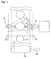
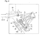
- FIG. 1 and Figure 2 show a specific construction of a spectrophotometer for measuring for example sugar content or acidity of the fruit or vegetables 5 constituting articles to be measured.
- This spectrophotometer comprises: a condensing lens 6 that receives for example transmitted light L that has been transmitted through the fruit or vegetables 5 from light emission means 4 such as a halogen lamp and light L1 therefrom that has not passed through the fruit or vegetables 5; a diffraction grating 9 that performs spectral separation of light that has passed through this condensing lens 6 after it has passed through a slit 7 and high cut-off filter 8; a line sensor 10 constituting a main light reception unit comprising a group of charge accumulation type photodetection elements for detecting light of each wavelength of first-order light ⁇ 1 (600 nm) to ⁇ 3 (1100 nm) obtained by spectral separation performed by this diffraction grating 9 and converting this into an amount of charge, which is accumulated; and an optical fiber 11 with
- FIG. 12 shown in Figure 1 is a photodetection unit of the photoelectric type for detecting light from a photoelectric light emission unit 13 and is arranged so as to be capable of ascertaining that fruit or vegetables 5 has moved to a prescribed position by interruption of light from the light emission unit 13 by fruit or vegetables 5 fed by a belt conveyor 14.
- 15 shown in Figure 1 is a rotary encoder for detecting for example the speed of rotation of the belt conveyor 14; the detection signal from the rotary encoder 15 and photoelectric light detection and emission units 12, 13 is applied to CPU 1 and 2, to be described, in order to obtain for example the feed speed of the belt conveyor 14, the size of the fruit or vegetables 5, the read timing of the fruit or vegetables 5, and the exposure time of the line sensor 10, based on the detection pulse number of this rotary encoder 15 and the time of interruption of light by the fruit or vegetables 5 at the photoelectric light detection and emission units 12, 13 (these two items will hereinbelow be referred to as a conveyor speed/fruit or vegetable size measuring unit, to be described).
- 29 shown in Figure 2 is a switch actuator for reference and offset.
- N shown in Figure 2 is an adjustment screw for adjusting the photodetection position of the sample photodetection window 11B.
- the necessary level (reference value) for aligning the maximum values is calculated from the values of the initially read pixel data of the line sensor 10 and gain correction is applied in pixel units to the pixels (4, 5..., n) of the main light reception unit in respect of the pixels (0, 1, 2, 3) and subsequent pixels of the sample-use light reception unit and these gains are successively set in the variable-gain type exponential amplification circuit, for each pixel.
- Figure 5(a) is a plan view of a photodetection unit wherein an optical fiber 11 is employed in the sample-use light reception unit of Figure 2 and whereby sample light is directed to the charge accumulation type line sensor 10 itself.
- Figure 5(b) is a plan view of a photodetection unit in which is arranged a photodiode D such as to input light in the vicinity of the aforesaid ⁇ 4 (820 nm), as with an optical fiber. If such a component arrangement construction is adopted, although for example a charge-voltage conversion and amplification circuit of the photodiode D constituting the sample photodetection window is necessary, the step of mounting an optical fiber on a line sensor can be dispensed with.
- the position of photodetection in the photodiode D of ⁇ 4 (second-order light) is adjacent to the position of installation of the line sensor 10 and, as shown in Figure 2, these can thus both be incorporated with a temperature-controlled block that is adjusted in temperature through a heat conduction plate 17 from a Peltier element 16.
- systems may also be considered in which a plurality of optical fiber circuits are employed or an arbitrary wavelength is selected by using a photodiode array for the photodiode D, or systems in which both these are combined, having a construction in which an optical input unit of optical fiber 11 from outside and photodiode D are moved to arbitrary positions.
- the arrangement of the pixels (photodiodes) of the line sensor 10 corresponds to the spectrum produced by the spectral separation achieved by the diffraction grating 9, these being arranged in sequence from short wavelength to long wavelength from the pixel (0) to the pixel (511). Also, a charge accumulation type photodetection element group 18 and preamplifier and sensor drive circuit 19 are provided in order to accumulate charges corresponding to the respective spectral components. The charge accumulation time and reading timing are controlled by the CPUs 1 and 2 and an analogue signal is output proportional to the accumulated charge in synchronization with the clock pulse from the CPUs 1 and 2.
- a switch circuit is required for changing over a circuit such as the aforesaid circuit 19 and line sensor.
- a circuit such as the aforesaid circuit 19 and line sensor.
- one end of the optical fiber 11 is mounted in the vicinity of the pixels (0, 1, 2, 3) while the other end thereof is mounted in the position of the wavelength where the amount of transmitted light by the article to be measured on the second order light from the diffraction grating 9 is greatest.
- the size (dimensions) of the fruit or vegetables and the speed of the belt conveyor 14 are calculated by the CPUs 1 and 2 using the signal obtained by the conveyor speed/fruit or vegetable size measurement unit 20 shown in Figure 3. In this way, an effective charge accumulation time is set and the line sensor 10 commences charge accumulation from the time-point where the optimum reading position of the fruit or vegetables reaches the optic axis.
- FIG. 21 shown in Figure 3 is a changeover unit for changing over optically the three factors: target, offset and reference, under the control of an actuator 29; a position detection section and drive section thereof are linked with the CPUs 1 and 2, so that, if required, a single one of these three factors can be selected.
- the size and the gaps of the fruit or vegetables move irregularly over the belt conveyor 14.
- Calculation of the optical reference (ND filter) and offset (optical screening) of the spectrophotometer is performed in accordance with the speed of movement and the condition regarding the intervals of the fruit or vegetables, during these gaps.
- a sensor unit temperature adjustment unit for monitoring the temperature of the Peltier element by means of the temperature sensor 23 shown in Figure 2 and controlling the temperature of the sensor unit to a suitable temperature by performing PID temperature control using the CPUs 1 and 2.
- a charge accumulation type line sensor current output type
- a charge accumulation type sensor is employed in which reverse bias voltage is applied to a photodiode.
- the sensor drive circuit 19 shown in Figure 3 is a preamplifier and sensor drive circuit: this drives the sensor unit under the control of signals from the CPUs 1 and 2, this drive timing being synchronized with that of the zero-point compensation circuit.
- the sensor drive circuit is of a type incorporating a charge-voltage conversion circuit.
- a digitally controlled exponential amplification circuit (also referred to as a variable-gain type exponential amplification circuit or simply gain amplifier) for obtaining a prescribed gain by converting the data from the CPUs 1 and 2 to analogue voltage by means of a D/A converter, not shown, and applying this analogue voltage to the gain control input terminal of a voltage controlled exponential amplifier; the gain of this digitally controlled exponential amplification circuit 24 is thus set by a digital instruction from the CPUs 1 and 2 in accordance with the digital signal from an A/D converter 26, to be described.
- the value of G M (the maximum gain), which is the base of the gain, is also set.
- a zero-point (0 line) compensation circuit for setting a base line with the significance of a zero for the electrical signal system and for fixing the value immediately prior to arrival of the analogue signal synchronized with the signal synchronization pulse amplified by the aforesaid circuits 19 and 24 to the value at this baseline: it comprises a clamp and filter circuit.
- FIG. 26 in Figure 3 is an A/D converter for converting the analogue signal regenerated by the zero-point compensation circuit 25 to digital form and has a sample-hold function at the input unit.
- FIG. 27 in Figure 3 is a computer in which the data of the A/D converter 26, the set value (exponent value) of the gain amplifier 24, the size of the fruit or vegetables and the exposure time are written in the shared memory of the CPUs 1 and 2 with the control timing from the CPUs 1 and 2; this computer performs necessary signal processing operations from this stored data and determines the contents of sugar, acid and other items by for example multiple regression analysis and P.L.S. analysis and outputs the results.
- a central processing unit comprising a CPU 1 and CPU 2 for performing the main control operations of the online spectrophotometer.
- digital comparison operation means that performs digital comparison operation of a predetermined reference value (value finally obtained by reading from said main light reception unit and determined such that it is an optimum value at which the maximum point of the wavelength characteristic of a wavelength or wavelength band required for analysis of the articles to be measured is not saturated and further such that the number of significant digits of the digital value is not reduced) and a digital value obtained by reading, through said zero-point compensation circuit 25, the amplified analogue voltage, which is an analogue voltage from the sample-use light reception unit, amplified by said variable-gain type amplification circuit 24, which is set to a pre-set fixed gain (i.e.
- gain setting means that sets the gain of said variable-gain type amplification circuit 24 such that the operation result i.e.
- the digital value from the A/D converter 26 from said digital comparison operation means substantially coincides with the reference value, in other words such that the digital value from the A/D converter 26 becomes an analogue level necessary for securing the number of significant digits that can be measured; and digital data reading means that reads the group of charges accumulated on said main light reception unit sequentially in pixel units as digital data through said preamplifier and sensor drive circuit 19, said variable-gain type amplification circuit 24, said zero-point compensation circuit 25 and said A/D converter 26.
- a spectrophotometer according to the present invention is advantageous in particular for measuring for example sugar content or acidity of fruit or vegetables as they are fed, but it can also be applied for example to measurement of the internal properties of potatoes or onions and the like.
Landscapes
- Physics & Mathematics (AREA)
- Spectroscopy & Molecular Physics (AREA)
- General Physics & Mathematics (AREA)
- Health & Medical Sciences (AREA)
- Life Sciences & Earth Sciences (AREA)
- Chemical & Material Sciences (AREA)
- Biochemistry (AREA)
- Analytical Chemistry (AREA)
- Engineering & Computer Science (AREA)
- General Health & Medical Sciences (AREA)
- Immunology (AREA)
- Pathology (AREA)
- Food Science & Technology (AREA)
- Medicinal Chemistry (AREA)
- Mathematical Physics (AREA)
- Theoretical Computer Science (AREA)
- Investigating Or Analysing Materials By Optical Means (AREA)
- Spectrometry And Color Measurement (AREA)
- Investigating Materials By The Use Of Optical Means Adapted For Particular Applications (AREA)
Applications Claiming Priority (2)
| Application Number | Priority Date | Filing Date | Title |
|---|---|---|---|
| JP2003368176A JP3931875B2 (ja) | 2003-10-29 | 2003-10-29 | 分光光度計 |
| PCT/JP2004/015899 WO2005040741A1 (ja) | 2003-10-29 | 2004-10-27 | 分光光度計 |
Publications (2)
| Publication Number | Publication Date |
|---|---|
| EP1679496A1 true EP1679496A1 (de) | 2006-07-12 |
| EP1679496A4 EP1679496A4 (de) | 2010-12-08 |
Family
ID=34510335
Family Applications (1)
| Application Number | Title | Priority Date | Filing Date |
|---|---|---|---|
| EP04793011A Withdrawn EP1679496A4 (de) | 2003-10-29 | 2004-10-27 | Spektrophotometer |
Country Status (12)
| Country | Link |
|---|---|
| US (1) | US7489398B2 (de) |
| EP (1) | EP1679496A4 (de) |
| JP (1) | JP3931875B2 (de) |
| KR (1) | KR101158693B1 (de) |
| CN (1) | CN1875251A (de) |
| AU (1) | AU2004284319B2 (de) |
| BR (1) | BRPI0416086A (de) |
| CA (1) | CA2544072A1 (de) |
| IL (1) | IL175129A0 (de) |
| MX (1) | MXPA06004811A (de) |
| NZ (1) | NZ546752A (de) |
| WO (1) | WO2005040741A1 (de) |
Cited By (2)
| Publication number | Priority date | Publication date | Assignee | Title |
|---|---|---|---|---|
| WO2012013476A1 (de) * | 2010-07-27 | 2012-02-02 | Evk Di Kerschhaggl Gmbh | Verfahren, sensoreinheit und maschine zum detektieren von "zuckerspitzen"-defekten in kartoffeln |
| CN104748851A (zh) * | 2014-08-15 | 2015-07-01 | 中国科学院上海技术物理研究所 | 提升凝视型红外光谱仪工作效率的变增益控制系统及方法 |
Families Citing this family (21)
| Publication number | Priority date | Publication date | Assignee | Title |
|---|---|---|---|---|
| JP2007047106A (ja) * | 2005-08-12 | 2007-02-22 | Mitsui Mining & Smelting Co Ltd | 分割測定法による青果物内部品質検査装置および青果物内部品質検査方法 |
| JP2008145269A (ja) * | 2006-12-11 | 2008-06-26 | Denso Corp | センサ装置 |
| KR100885479B1 (ko) * | 2007-06-19 | 2009-02-24 | 마루엘에스아이 주식회사 | 라인 센서 및 그 제어 방법 |
| JP5321260B2 (ja) * | 2009-06-11 | 2013-10-23 | ソニー株式会社 | 光学的測定装置、並びにフローサイトメーター及び光学的測定方法 |
| JP5636870B2 (ja) * | 2009-10-28 | 2014-12-10 | 一般財団法人雑賀技術研究所 | オンライン型非破壊分光分析装置 |
| US20120231534A1 (en) | 2011-03-07 | 2012-09-13 | Carroll Wallace E | Spectrometric device |
| US20140125969A1 (en) * | 2012-11-02 | 2014-05-08 | Lawson Health Research Institute | Apparatus and methods for performing optical tomography on dosimeters for calibrating radiotherapy equipment |
| TW201435317A (zh) | 2013-02-28 | 2014-09-16 | Otsuka Denshi Kk | 分光光度計及分光光度測定方法 |
| US9508765B2 (en) * | 2014-09-02 | 2016-11-29 | Shimadzu Corporation | Photodiode array detector with different charge accumulation time for each light receiving element within one unit |
| US10064259B2 (en) * | 2016-05-11 | 2018-08-28 | Ford Global Technologies, Llc | Illuminated vehicle badge |
| JP6826802B2 (ja) * | 2016-06-06 | 2021-02-10 | 一般財団法人雑賀技術研究所 | 青果物の可食部の機能性色素成分の測定方法及び装置 |
| CN107101583A (zh) * | 2017-03-14 | 2017-08-29 | 广东工业大学 | 基于纵横转换放大光栅尺的图像处理方法及其应用 |
| KR102500765B1 (ko) | 2017-11-22 | 2023-02-17 | 삼성전자주식회사 | 분광기, 분광기의 출력이득 조절 방법, 생체정보 측정 장치 및 방법 |
| JP6568245B2 (ja) * | 2018-01-24 | 2019-08-28 | Ckd株式会社 | 検査装置、ptp包装機、及び、検査装置の較正方法 |
| CN110749545B (zh) * | 2018-07-24 | 2022-04-29 | 谱钜科技股份有限公司 | 光谱仪引擎及其调整方法 |
| JP7325383B2 (ja) * | 2020-07-20 | 2023-08-14 | アンリツ株式会社 | 物品検査装置 |
| CN113109275B (zh) * | 2021-05-18 | 2025-04-15 | 北京雪域飞虹环保科技有限公司 | 一种降低温漂、提高水体污染因子检测精度的方法和系统 |
| KR102600767B1 (ko) * | 2021-05-20 | 2023-11-10 | (주)파이버피아 | 금속이온의 농도 측정 장치 및 그 방법 |
| JP7823485B2 (ja) * | 2022-04-14 | 2026-03-04 | 株式会社リコー | 画像読取装置 |
| CN116429272A (zh) * | 2023-03-24 | 2023-07-14 | 西北工业大学 | 一种适用于红外多光谱焦平面的盲元校正方法 |
| CN118308453B (zh) * | 2024-05-07 | 2025-03-18 | 广州一微生物科技有限公司 | 一种针对大体积深孔板在菌种培养过程中的光电信号采集方法 |
Family Cites Families (10)
| Publication number | Priority date | Publication date | Assignee | Title |
|---|---|---|---|---|
| JPS5937767B2 (ja) * | 1977-04-20 | 1984-09-12 | オリンパス光学工業株式会社 | 測光装置 |
| JPS55126834A (en) | 1979-03-23 | 1980-10-01 | Toshiba Corp | Automatic spectral radiation meter |
| JPS5919839A (ja) | 1982-07-26 | 1984-02-01 | Hiroyasu Funakubo | 液体クロマトグラフイ−における検出成分処理方法 |
| JPH07113582B2 (ja) * | 1987-02-17 | 1995-12-06 | 株式会社島津製作所 | 分光分析装置 |
| JPS63201538A (ja) | 1987-02-18 | 1988-08-19 | Japan Spectroscopic Co | 分光光度計 |
| JPS6472016A (en) | 1988-03-16 | 1989-03-16 | Minolta Camera Kk | Solid-state image pickup device for spectral measurement |
| JPH0287029A (ja) * | 1988-09-24 | 1990-03-27 | Shimadzu Corp | 分光光度計 |
| US5412468A (en) | 1993-03-09 | 1995-05-02 | The Perkin-Elmer Corporation | Grouping of spectral bands for data acquisition in a spectrophotometer |
| CA2347370A1 (en) * | 1998-10-26 | 2000-05-04 | Meade Instruments Corporation | Fully automated telescope system with distributed intelligence |
| JP2002098636A (ja) * | 2000-09-27 | 2002-04-05 | Kubota Corp | 分光分析装置 |
-
2003
- 2003-10-29 JP JP2003368176A patent/JP3931875B2/ja not_active Expired - Fee Related
-
2004
- 2004-10-27 MX MXPA06004811A patent/MXPA06004811A/es not_active Application Discontinuation
- 2004-10-27 BR BRPI0416086-0A patent/BRPI0416086A/pt not_active Application Discontinuation
- 2004-10-27 CN CNA200480032377XA patent/CN1875251A/zh active Pending
- 2004-10-27 EP EP04793011A patent/EP1679496A4/de not_active Withdrawn
- 2004-10-27 KR KR1020067008031A patent/KR101158693B1/ko not_active Expired - Lifetime
- 2004-10-27 WO PCT/JP2004/015899 patent/WO2005040741A1/ja not_active Ceased
- 2004-10-27 AU AU2004284319A patent/AU2004284319B2/en not_active Ceased
- 2004-10-27 US US10/577,243 patent/US7489398B2/en not_active Expired - Fee Related
- 2004-10-27 NZ NZ546752A patent/NZ546752A/en not_active IP Right Cessation
- 2004-10-27 CA CA 2544072 patent/CA2544072A1/en not_active Abandoned
-
2006
- 2006-04-24 IL IL175129A patent/IL175129A0/en unknown
Non-Patent Citations (2)
| Title |
|---|
| No further relevant documents disclosed * |
| See also references of WO2005040741A1 * |
Cited By (6)
| Publication number | Priority date | Publication date | Assignee | Title |
|---|---|---|---|---|
| WO2012013476A1 (de) * | 2010-07-27 | 2012-02-02 | Evk Di Kerschhaggl Gmbh | Verfahren, sensoreinheit und maschine zum detektieren von "zuckerspitzen"-defekten in kartoffeln |
| CN103119423A (zh) * | 2010-07-27 | 2013-05-22 | Evkdi克施哈格有限责任公司 | 用于探测马铃薯中的“糖尖峰”缺陷的方法、传感器单元和机器 |
| CN103119423B (zh) * | 2010-07-27 | 2016-01-20 | Evkdi克施哈格有限责任公司 | 用于探测马铃薯中的“糖尖峰”缺陷的方法、传感器单元和机器 |
| US9910024B2 (en) | 2010-07-27 | 2018-03-06 | Insort Gmbh | Method, sensor unit and machine for detecting “sugar top” defects in potatoes |
| CN104748851A (zh) * | 2014-08-15 | 2015-07-01 | 中国科学院上海技术物理研究所 | 提升凝视型红外光谱仪工作效率的变增益控制系统及方法 |
| CN104748851B (zh) * | 2014-08-15 | 2017-02-01 | 中国科学院上海技术物理研究所 | 提升凝视型红外光谱仪工作效率的变增益控制系统及方法 |
Also Published As
| Publication number | Publication date |
|---|---|
| AU2004284319B2 (en) | 2009-11-05 |
| US7489398B2 (en) | 2009-02-10 |
| IL175129A0 (en) | 2006-09-05 |
| JP3931875B2 (ja) | 2007-06-20 |
| JP2005134164A (ja) | 2005-05-26 |
| CN1875251A (zh) | 2006-12-06 |
| MXPA06004811A (es) | 2006-07-10 |
| CA2544072A1 (en) | 2005-05-06 |
| BRPI0416086A (pt) | 2007-01-02 |
| US20070081160A1 (en) | 2007-04-12 |
| AU2004284319A1 (en) | 2005-05-06 |
| NZ546752A (en) | 2010-03-26 |
| WO2005040741A1 (ja) | 2005-05-06 |
| KR20060120046A (ko) | 2006-11-24 |
| EP1679496A4 (de) | 2010-12-08 |
| KR101158693B1 (ko) | 2012-06-22 |
Similar Documents
| Publication | Publication Date | Title |
|---|---|---|
| US7489398B2 (en) | Spectrophotometer | |
| US5132538A (en) | Measuring percentage of protein in whole grain samples | |
| US7316322B2 (en) | Quality evaluation apparatus for fruits and vegetables | |
| US4627008A (en) | Optical quantitative analysis using curvilinear interpolation | |
| EP0083761B1 (de) | Vorrichtung zur Kontrolle der Ausgangsgrössen von lichtempfindlichen Detektoren für Photometer | |
| US7511255B2 (en) | Spectrophotometer with optical system for spectrally dispersing measurement light and photodiode array | |
| EP0420135B1 (de) | Spektrophotometer mit Fehlerkorrektur durch schnelle Abtastung | |
| WO2016129033A1 (ja) | マルチチャンネル分光光度計及びマルチチャンネル分光光度計用データ処理方法 | |
| EP1252500A2 (de) | Integrierter optischer block für die spektroskopie | |
| JPH07229840A (ja) | 光学的測定方法及びその装置 | |
| US11802829B2 (en) | Method and system for broadband photoreflectance spectroscopy | |
| KR100731569B1 (ko) | 청과물의 내부품질을 측정하는 측정장치 및 측정방법 | |
| JP5707739B2 (ja) | 分光測定装置 | |
| JP2002098636A (ja) | 分光分析装置 | |
| US7692790B2 (en) | Grating spectrometer system and method for the acquisition of measured values | |
| US20060076502A1 (en) | Method and apparatus for a photodetector responsive over a selectable wavelength range | |
| JPH11337481A (ja) | 青果物内部品質測定装置及び測定方法 | |
| JPS58111728A (ja) | 光学的測定装置 | |
| JPH11337482A (ja) | 青果物内部品質測定装置及び測定方法 | |
| Krause | A Theoretical Model for Measuring and Sensor Characterization in Optical Spectroscopy | |
| Min et al. | Design of A Hyperspectral Nitrogen Sensing System for Citrus | |
| JPH0359443A (ja) | 分光分析装置 |
Legal Events
| Date | Code | Title | Description |
|---|---|---|---|
| PUAI | Public reference made under article 153(3) epc to a published international application that has entered the european phase |
Free format text: ORIGINAL CODE: 0009012 |
|
| 17P | Request for examination filed |
Effective date: 20060509 |
|
| AK | Designated contracting states |
Kind code of ref document: A1 Designated state(s): AT BE BG CH CY CZ DE DK EE ES FI FR GB GR HU IE IT LI LU MC NL PL PT RO SE SI SK TR |
|
| DAX | Request for extension of the european patent (deleted) | ||
| A4 | Supplementary search report drawn up and despatched |
Effective date: 20101105 |
|
| 17Q | First examination report despatched |
Effective date: 20110221 |
|
| STAA | Information on the status of an ep patent application or granted ep patent |
Free format text: STATUS: THE APPLICATION IS DEEMED TO BE WITHDRAWN |
|
| 18D | Application deemed to be withdrawn |
Effective date: 20130716 |