EP1680789B1 - Agencement de collimation de rayonnement electromagnetique - Google Patents
Agencement de collimation de rayonnement electromagnetique Download PDFInfo
- Publication number
- EP1680789B1 EP1680789B1 EP04769938A EP04769938A EP1680789B1 EP 1680789 B1 EP1680789 B1 EP 1680789B1 EP 04769938 A EP04769938 A EP 04769938A EP 04769938 A EP04769938 A EP 04769938A EP 1680789 B1 EP1680789 B1 EP 1680789B1
- Authority
- EP
- European Patent Office
- Prior art keywords
- collimator
- microcollimator
- arrangement
- structures
- macrocollimator
- Prior art date
- Legal status (The legal status is an assumption and is not a legal conclusion. Google has not performed a legal analysis and makes no representation as to the accuracy of the status listed.)
- Expired - Lifetime
Links
Images



Classifications
-
- G—PHYSICS
- G21—NUCLEAR PHYSICS; NUCLEAR ENGINEERING
- G21K—HANDLING OF PARTICLES OR IONISING RADIATION NOT OTHERWISE PROVIDED FOR; IRRADIATION DEVICES; GAMMA RAY OR X-RAY MICROSCOPES
- G21K1/00—Arrangements for handling particles or ionising radiation, e.g. focusing or moderating
- G21K1/02—Arrangements for handling particles or ionising radiation, e.g. focusing or moderating using diaphragms, collimators
Definitions
- the invention relates to an arrangement for collimating electromagnetic radiation, in particular X-ray radiation.
- the invention also relates to an X-ray detector and an X-ray device which are equipped with such an arrangement. Furthermore, the invention relates to a method of producing an arrangement for collimating electromagnetic radiation.
- Such a collimator block formed from a number of individual elements is placed in a frame in a last production step, wherein the frame has a cutout which extends in the transmission direction and wherein the cutout is greater than the collimator block.
- the free interspaces between frame and collimator block which extend in the transmission direction are then filled with a radiation-proof material (lead).
- a collimator with collimator channels for X-ray radiation which can be used in an Anger camera is thus provided.
- Radiography detector may for instance be up to 50 x 50 cm 2
- those of a detector as used in computer tomography (CT) may be 100 x 4 cm 2
- Even much larger detectors of up to around 100 x 40 cm 2 are conceivable, particularly in the case of CT.
- Scattered radiation is produced when X-ray quanta undergo an interaction with the object which interaction does not lead to absorption. Such interaction processes are for example Compton scattering and Rayleigh scattering.
- Scattered X-ray quanta generate a background signal which reduces the contrast and contribute to noise.
- the proportion of scattered X-ray quanta may easily be 90% or more.
- the object itself is a source of radiation, for instance in the case of single photon emission computed tomography (SPECT) or positron emission tomography (PET) or in the case of dedicated measurements of scattered X-ray quanta.
- SPECT single photon emission computed tomography
- PET positron emission tomography
- Each part of the detector then receives X-ray quanta from each part of the object.
- meaningful measurements can often only be carried out when a certain detector part only receives radiation from an area of the object determined by a collimation device.
- collimators which are arranged between the detector and the object and serve to suppress certain parts of the X-ray radiation.
- Collimators have collimator channels which extend in a linear manner.
- a collimator channel consists of a radiation-transparent inner channel, or an inner channel that only absorbs radiation to a slight extent, and radiation-opaque collimator channel walls, or collimator channel walls which absorb radiation to a greater extent.
- Each collimator channel is distinguished by extending in a transmission direction. The collimator channel walls border the inner channel essentially parallel to the transmission direction.
- the transmission direction may be the same for all collimator channels, for instance as in the case of a SPECT collimator in which all the collimator channels are aligned parallel to one another, or else the transmission direction may change from collimator channel to collimator channel, for instance as in the case of a CT collimator, the individual collimator channels of which are aligned on the focus point of an X-ray source.
- Radiation which enters a collimator channel and differs in terms of its propagation direction from the transmission direction of the collimator channel is highly likely to be absorbed in the radiation-opaque collimator channel walls. In local terms, a collimator therefore essentially allows through only radiation having a propagation direction which corresponds to the transmission direction.
- Collimators for collimating X-ray radiation are typically made from a material which greatly absorbs the X-ray radiation used, for instance from a heavy metal such as lead.
- a heavy metal such as lead.
- Other metals may also be used, such as tungsten, tantalum, molybdenum or alloys such as bronze with a high tin content or compounds with a heavy metal such as tungsten oxide or tungsten carbide, or else use may be made of hybrid materials which consist for instance of a plastic matrix comprising embedded metal powders.
- low-energy X-ray radiation (as used for example in mammography), it is also possible to use copper, titanium or iron or materials with similar X-ray absorption.
- the collimator arrangement according to the invention has a macrocollimator which defines the overall geometry. Since the macrocollimator has cutouts for microcollimators, the macrocollimator requires only a small number of inner structures.
- the macrocollimator may then be produced with high precision (for instance by wire EDM or by stacking etched metal sheets on top of one another) without entailing high costs.
- the fine structure of the collimator is produced by the microcollimator structures. These may then be produced in inexpensive methods (for instance by means of a casting process - e.g. lead casting or plastic injection molding, with it being possible for metal powder to be embedded in the plastic - or by simply placing sheets of metal inside one another in order to form a microcollimator with parallel collimator channels).
- the precision of the microcollimators must be sufficient only for part of the overall collimator surface.
- One embodiment of a collimator arrangement according to the invention has microcollimator structures which have collimator channels that at the side (that is to say perpendicular to the transmission direction) are not completely enclosed by lamellae.
- the complete enclosure to form a collimator channel is achieved by the walls of the macrocollimator when the microcollimator structure is positioned in the macrocollimator. In this way it is possible to make the macrocollimator walls as thick as the lamellae thickness without the entire wall thickness between two inner channels separated by a macrocollimator wall becoming greater than the wall thickness between two inner channels separated by a lamella of a microcollimator structure.
- a guide structure aids the precise positioning of a microcollimator structure relative to the macrocollimator.
- a guide structure may be for example a groove or a guide rail.
- a positioning structure is used for the precise positioning of the collimator arrangement relative to an external unit, for instance a pixelated detector. It is then possible to assign the collimator channels particularly precisely to the individual detector pixels, for example such that the collimator channel walls are in each case positioned between two detector pixels and therefore a shading of the radiation on the individual detector pixels by the collimator channel walls is avoided.
- the cutouts are aligned in a focusing manner.
- microcollimator structures that collimate in a parallel manner and are cost-effective to produce can be positioned in the individual cutouts and nevertheless an overall focusing of the collimator arrangement is achieved. Since collimator channels which are locally aligned in parallel lead to radiation shading in the case of focusing collimation that is to be achieved overall, the geometry of the cutouts and of the microcollimators must be selected such that an acceptable level of shading is not exceeded.
- a collimator arrangement according to the invention can be advantageously used in an X-ray detector unit.
- elements of the X-ray detector unit are connected integrally with the microcollimator structures.
- an X-ray converter e.g. a scintillator
- an X-ray converter may for instance in each case be accommodated in a collimator channel.
- the invention also relates to an X-ray device in which a collimator arrangement according to the invention is used.
- This may be arranged in the X-ray device for example in a manner such that it can be replaced or as part of the X-ray detector unit.
- the invention furthermore relates to a method of producing a collimator arrangement, wherein in one embodiment microcollimator structures are produced by a casting or injection-molding process (for example a lead casting process or a plastic injection-molding process).
- a casting or injection-molding process for example a lead casting process or a plastic injection-molding process.
- Fig. 1 shows a schematic diagram of a macrocollimator 1 in which one microcollimator structure 2 is positioned by way of example in one of the cutouts 3.
- Fig. 2 shows one embodiment of a microcollimator structure 2.
- a microcollimator structure may be produced for instance in a casting or injection-molding method. Lead casting and plastic injection-molding may be mentioned here as examples.
- X-ray-absorbing powders e.g. tungsten powder with particle sizes in the micrometer range
- Another method of producing a microcollimator structure is placing sheets that absorb electromagnetic radiation inside one another. This can easily be done in the case of collimator channels which are aligned in parallel.
- the microcollimator structure shown in Fig. 2 has transparent collimator channels which in each case extend in the transmission direction.
- transparent is to be understood as meaning that, for example, even fixings with low radiation absorption (e.g. a fixing plate made of plastic which fixes the positioned microcollimator structures in the macrocollimator) do not alter the transparency.
- the radiation-transparent inner channels are formed by air and the collimator channel walls are formed by lamellae, the extension direction of which is essentially the same as the transmission direction of the respective collimator channels.
- a collimator arrangement according to the invention shown in Fig. 1 shows that, given a suitably precise production of the macrocollimator, very large collimator arrangements can be produced with high overall precision and low costs.
- the costs for the precise macrocollimator are low since the cutouts 3 may be selected to be large compared to the desired collimator channels and therefore only a small number of precise structures of the macrocollimator have to be produced.
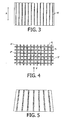
- Fig. 3 shows a side view of a microcollimator structure 2 with collimator channels which are aligned in parallel (this is also referred to as a parallel collimator).
- the transmission direction runs in the direction of the double arrow A.
- Parallel collimator arrangements are used for example to obtain a parallel projection image of an extended source distribution, for instance in the case of SPECT.
- the hatched lamellae 4' are in this embodiment to be understood as running perpendicular to the plane of the paper.
- Lamellae 4" (cf. Fig. 4 ) are arranged at regular intervals parallel to the plane of the paper, said lamellae together with the lamellae running perpendicular to the plane of the paper bordering inner channels of collimator channels.
- Fig. 4 shows an aspect of the microcollimator structure of Fig. 3 .
- the lamellae 4 enclose collimator channels 5 which are transparent in the transmission direction, such that the collimator channels 5 have a rectangular cross section.
- there are lamellae 4' and lamellae 4" which run perpendicular to one another and as a result form the rectangular cross section of the collimator channels 5.
- collimator channels 5' which are open at the side on account of not being completely enclosed by lamellae.
- a microcollimator structure of the type shown which do not have any collimator channels 5' that are open at the side or which have collimator channels 5' that are open at the side on only one or two or three sides.
- Fig. 5 shows a side view of a microcollimator structure with collimator channels which are aligned on a point (this is also referred to as a focusing collimator).
- the hatched lamellae which run perpendicular to the plane of the paper are aligned on a point.
- a microcollimator structure is advantageous for example when the radiation from a point source, e.g. an X-ray source, is to be allowed through and radiation from other sources, for instance scattered radiation from an irradiated object, is to be absorbed in the lamellae.
- the lamellae which run in the plane of the paper either may extend parallel to the plane of the paper, which leads to focusing of the overall microcollimator structure on a line, or are likewise aligned on the source point, which means that the lamellae are in each case arranged perpendicular to the plane of the paper at such an angle that all the collimator channels 5, 5' produced are aligned on a source point.
- the transmission direction for each collimator channel then points in each case to this focus point.
- collimator channels of different geometric shape may also be enclosed by the lamellae, for instance collimator channels of hexagonal or round cross section.
- the shape of the cross section of different collimator channels may also be different.
- Fig. 6 shows an aspect of a macrocollimator 1 with two cutouts 3, wherein notches 6 are made at some points in the walls of the macrocollimator.
- Fig. 7 shows the collimator arrangement with microcollimator structures 2, 2', 2" positioned in the cutouts.
- One microcollimator structure is positioned in the left-hand cutout, as is known from Figs. 3 to 5 .
- the left-hand cutout is filled by a single microcollimator structure.
- the notches 6 are used as guide structures which position the microcollimator structure relative to the macrocollimator. A precise positioning of the microcollimator structures is facilitated by guide structures.
- the guide structures may also be formed by other structures known to the person skilled in the art, such as dents, or by guide rails which are additionally attached.
- the walls of the macrocollimator in this embodiment enclose the open collimator channels of the microgrid structure, so that completely enclosed collimator channels are formed.
- open collimator channels By means of open collimator channels, the situation is avoided whereby the outer wall thickness of the microcollimator and the wall thickness of the macrocollimator are added together. For a uniform size and a uniform spacing of all collimator channels of the collimator arrangement, the outer walls of the micro collimator structures would then have to be made very thin compared to the thickness of the lamellae.
- a microcollimator structure according to the invention may also have collimator channels which are filled with a material that is only slightly absorbent, such as a polyurethane foam. This is advantageous in order to increase the stability of the microcollimator structure.
- a material that is only slightly absorbent such as a polyurethane foam.
- a slightly absorbent material for instance a hard foam
- lamellae which are unstable per se for example thin lead lamellae
- the collimator channels are to be regarded as transparent since the X-ray radiation is attenuated only a little within the slightly absorbent material compared to the absorbent lamellae.
- microcollimator structures are positioned in the right-hand cutout of the macrocollimator in Fig. 7 .
- this embodiment which is shown by way of example, there are alternately comb sheets 2' and flat sheets 2" which in their entirety fill the cutout such that collimator channels are formed in this case too.
- microcollimator structures 2" which have neither closed nor open collimator channels. Closed collimator channels 5 are formed only in collaboration with other microcollimator structures 2' and the walls of the macrocollimator 1.
- sheets of different form may also be used as microcollimator structures if said sheets can be placed in the cutouts such that collimator channels are formed. Such sheets may be for example deep-drawn sheets.
- Fig. 8 shows a side view of a microcollimator structure 2 on which positioning structures 7 are fitted.
- the positioning structures 7 may in this case have been formed integrally during the production process or be attached subsequently.
- the positioning structures 7 allow the positioning of the microcollimator structure 2 relative to an external element 10.
- the positioning structures 7 engage in recessed parts of the external element 10. A precise alignment of the collimator channels with respect to structures of the external element 10 (for instance photodiodes for measuring electromagnetic radiation) can thus be achieved.
- Fig. 9 shows a side view of a collimator arrangement with a macrocollimator 1 and microcollimator structures 2 positioned in the cutouts of the macrocollimator.
- the macrocollimator 1 is designed to be focusing, wherein the cutouts are designed such that their respective collimation directions are aligned on one point. If the microcollimator structures, as in the example shown, are designed to collimate in parallel, then the collimator arrangement nonetheless still has a focusing alignment overall on account of the macrocollimator.
- the size of the cutouts may be selected such that a focusing collimation of the overall collimator arrangement that is acceptable for the respective application is nevertheless produced.
- the use of parallel microcollimator structures offers the advantage that the latter can be produced more easily than focusing microcollimator structures.
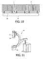
- Fig. 10 schematically shows an X-ray detector in side view, in which a collimator arrangement according to the invention is used.
- Scintillator photodiode matrix modules 10 are arranged on a substrate 11.
- X-ray radiation which impinges on a scintillator and interacts with the latter is converted into optical light which the photodiodes measure and convert into an electrical signal.
- the collimator arrangement is arranged between the detector and the radiation source.
- Fig. 11 shows by way of example a medical X-ray imaging device 20 with an X-ray source 22 and an X-ray detector 21, in which a collimator arrangement 23 according to the invention is used, said collimator arrangement in this embodiment being arranged on the X-ray detector 21 between the X-ray source 22 and the X-ray detector 21.
Landscapes
- Physics & Mathematics (AREA)
- Spectroscopy & Molecular Physics (AREA)
- Engineering & Computer Science (AREA)
- General Engineering & Computer Science (AREA)
- High Energy & Nuclear Physics (AREA)
- Apparatus For Radiation Diagnosis (AREA)
- Analysing Materials By The Use Of Radiation (AREA)
- Measurement Of Radiation (AREA)
- Shielding Devices Or Components To Electric Or Magnetic Fields (AREA)
- Optical Elements Other Than Lenses (AREA)
Claims (10)
- Agencement de collimation de rayonnement électromagnétique, comprenant :- un macro-collimateur (1) qui définit une géométrie globale et qui comporte au moins deux découpes (3) ; et- une structure fine du collimateur produite par des structures de micro-collimateur (2, 2', 2") qui sont positionnées dans les découpes du macro-collimateur et ont des lamelles (4) qui absorbent le rayonnement électromagnétique, de sorte que des canaux de collimateur (5) soient formés dans les découpes, lesquels canaux de collimateur dans chaque cas s'étendant de manière à être transparents dans une direction de transmission (A).
- Agencement selon la revendication 1, caractérisée en ce que l'une des structures de micro-collimateur (2, 2', 2") a au moins un canal de collimateur (5') perpendiculaire à la direction de transmission (A) qui n'est pas complètement enclos par des lamelles et l'enceinte est terminée par des parois du macro-collimateur (1).
- Agencement selon la revendication 1 ou 2, caractérisé en ce qu'il a au moins une structure de guidage (6) qui est fournie pour positionner au moins l'une des structures de micro-collimateur (2, 2', 2") par rapport au macro-collimateur (1).
- Agencement selon l'une quelconque des revendications 1 à 3, caractérisé en ce qu'il a au moins une structure de positionnement (7) qui est fournie pour positionner l'agencement par rapport à une unité externe (10).
- Agencement selon l'une quelconque des revendications 1 à 4, caractérisé en ce que les découpes (3) sont agencées d'une manière de focalisation.
- Unité de détecteur de rayons X comprenant un agencement selon l'une quelconque des revendications 1 à 5.
- Unité de détecteur de rayons X selon la revendication 6, caractérisée en ce qu'au moins l'une des structures de micro-collimateur (2, 2', 2") est intégralement pourvue d'éléments de l'unité de détecteur de rayons X (10).
- Dispositif de rayons X comprenant un agencement selon l'une quelconque des revendications 1 à 7.
- Procédé de production d'un agencement de collimation de rayonnement électromagnétique, ledit procédé comprenant les étapes suivantes :- la fabrication d'un macro-collimateur (1) qui définit une géométrie globale et qui comporte au moins deux découpes (3) ;- la fabrication de structures de micro-collimateur (2, 2', 2") qui ont des lamelles (4) qui absorbent le rayonnement électromagnétique pour produire une structure fine du collimateur,- l'insertion des structures de micro-collimateur (2, 2', 2") dans les découpes (3) de sorte que des canaux de collimateur (5) soient formés dans les découpes, lesquels canaux de collimateur dans chaque cas s'étendant de manière à être transparents dans une direction de transmission (A).
- Procédé selon la revendication 9, caractérisé en ce qu'au moins l'une des structures de micro-collimateur (2, 2', 2") a été produite par un procédé de coulage ou de moulage par injection.
Priority Applications (1)
| Application Number | Priority Date | Filing Date | Title |
|---|---|---|---|
| EP04769938A EP1680789B1 (fr) | 2003-09-12 | 2004-09-03 | Agencement de collimation de rayonnement electromagnetique |
Applications Claiming Priority (3)
| Application Number | Priority Date | Filing Date | Title |
|---|---|---|---|
| EP03103365 | 2003-09-12 | ||
| PCT/IB2004/051683 WO2005027143A2 (fr) | 2003-09-12 | 2004-09-03 | Agencement de collimation de rayonnement electromagnetique |
| EP04769938A EP1680789B1 (fr) | 2003-09-12 | 2004-09-03 | Agencement de collimation de rayonnement electromagnetique |
Publications (2)
| Publication Number | Publication Date |
|---|---|
| EP1680789A2 EP1680789A2 (fr) | 2006-07-19 |
| EP1680789B1 true EP1680789B1 (fr) | 2011-11-16 |
Family
ID=34306926
Family Applications (1)
| Application Number | Title | Priority Date | Filing Date |
|---|---|---|---|
| EP04769938A Expired - Lifetime EP1680789B1 (fr) | 2003-09-12 | 2004-09-03 | Agencement de collimation de rayonnement electromagnetique |
Country Status (6)
| Country | Link |
|---|---|
| US (1) | US7356125B2 (fr) |
| EP (1) | EP1680789B1 (fr) |
| JP (1) | JP4510823B2 (fr) |
| CN (1) | CN1849672B (fr) |
| AT (1) | ATE534124T1 (fr) |
| WO (1) | WO2005027143A2 (fr) |
Families Citing this family (19)
| Publication number | Priority date | Publication date | Assignee | Title |
|---|---|---|---|---|
| JP2009509133A (ja) * | 2005-09-19 | 2009-03-05 | コーニンクレッカ フィリップス エレクトロニクス エヌ ヴィ | 電磁放射線の選択的吸収のための格子,及びその製造方法 |
| JP5047826B2 (ja) * | 2008-01-31 | 2012-10-10 | ジーイー・メディカル・システムズ・グローバル・テクノロジー・カンパニー・エルエルシー | コリメータ、コリメータ積層体、およびマルチモダリティシステム |
| WO2010007544A1 (fr) * | 2008-07-14 | 2010-01-21 | Koninklijke Philips Electronics N.V. | Grille d'anti-diffusion |
| US8385499B2 (en) * | 2009-12-28 | 2013-02-26 | General Electric Company | 2D reflector and collimator structure and method of manufacturing thereof |
| CN102343500B (zh) * | 2010-08-04 | 2014-04-02 | 中国科学院高能物理研究所 | 高精度准直器及其加工方法 |
| JP5836011B2 (ja) * | 2010-09-22 | 2015-12-24 | 株式会社東芝 | X線CT(ComputedTomography)装置、放射線検出器及びその製造方法 |
| US20120087462A1 (en) * | 2010-10-12 | 2012-04-12 | Abdelaziz Ikhlef | Hybrid collimator for x-rays and method of making same |
| JP2014003988A (ja) * | 2010-10-19 | 2014-01-16 | Fujifilm Corp | 放射線画像撮影用グリッド及びその製造方法、並びに放射線画像撮影システム |
| DE102010062133B4 (de) * | 2010-11-29 | 2017-02-23 | Siemens Healthcare Gmbh | Kollimator für einen Strahlendetektor und Verfahren zur Herstellung eines solchen Kollimators sowie Verfahren zur Herstellung eines Kollimatoren aufweisenden Strahlendetektors |
| US20120163553A1 (en) * | 2010-12-27 | 2012-06-28 | Analogic Corporation | Three-dimensional metal printing |
| US20120305781A1 (en) | 2011-05-31 | 2012-12-06 | Jansen Floribertus P M Heukensfeldt | System and method for collimation in diagnostic imaging systems |
| US20130329862A1 (en) * | 2012-06-12 | 2013-12-12 | University Of Rochester | Backscatter reduction device (bsr) |
| US9285327B2 (en) * | 2013-02-06 | 2016-03-15 | Zhengrong Ying | Adjustable photon detection systems for multi-slice X-ray computed tomography systems |
| WO2016076824A1 (fr) * | 2014-11-10 | 2016-05-19 | Halliburton Energy Services, Inc. | Appareil, procédés et systèmes de détection d'énergie |
| CN105427355B (zh) * | 2015-11-26 | 2018-04-03 | 上海联影医疗科技有限公司 | 罩壳、x射线图像的散射成分计算、重建的方法及装置 |
| US10401507B2 (en) * | 2016-03-24 | 2019-09-03 | Kabushiki Kaisha Toshiba | Collimator, radiation detector, and radiation examination apparatus |
| CN106226916A (zh) * | 2016-07-26 | 2016-12-14 | 中国科学院高能物理研究所 | 光学准直器及其加工方法 |
| DE102016226032A1 (de) * | 2016-12-22 | 2018-06-28 | Fraunhofer-Gesellschaft zur Förderung der angewandten Forschung e.V. | Optische Anordnung zur Unterdrückung von Artefakten bei Röntgenuntersuchungen und Verfahren zu ihrer Herstellung |
| DE102021209254B4 (de) * | 2021-08-24 | 2023-04-27 | Siemens Healthcare Gmbh | Lamelle zum Kollimieren einer Therapiestrahlung |
Family Cites Families (28)
| Publication number | Priority date | Publication date | Assignee | Title |
|---|---|---|---|---|
| US4127398A (en) | 1963-09-18 | 1978-11-28 | Ni-Tec, Inc. | Multiple-channel tubular devices |
| US4054800A (en) * | 1975-07-28 | 1977-10-18 | Engineering Dynamics Corporation | Methods of collimator fabrication |
| US3988589A (en) * | 1975-07-28 | 1976-10-26 | Engineering Dynamics Corporation | Methods of collimator fabrication |
| US4250392A (en) * | 1979-02-27 | 1981-02-10 | Engineering Dynamics Corporation | Bi-focal collimator |
| SE423458B (sv) * | 1980-09-10 | 1982-05-03 | Agne Larsson | Anordning vid en kamera innefattande en manghalskollimator |
| JPS6034018A (ja) | 1983-08-06 | 1985-02-21 | Canon Inc | X線コリメ−タと露光装置 |
| US4706269A (en) * | 1985-03-11 | 1987-11-10 | Reina Leo J | Anti-scatter grid structure |
| JPH0675570B2 (ja) * | 1985-09-11 | 1994-09-28 | 株式会社東芝 | X線ct装置 |
| US4672648A (en) * | 1985-10-25 | 1987-06-09 | Picker International, Inc. | Apparatus and method for radiation attenuation |
| JPH03120500A (ja) * | 1989-10-04 | 1991-05-22 | Toshiba Corp | 多孔コリメータ及びその製造方法 |
| US5309911A (en) * | 1990-10-29 | 1994-05-10 | Scinticor Incorporated | Radionuclide angiographic collimator system |
| JPH04297899A (ja) | 1991-03-27 | 1992-10-21 | Toshiba Corp | コリメータ製造方法及び該製造方法で得るコリメータ |
| US5418833A (en) * | 1993-04-23 | 1995-05-23 | The Regents Of The University Of California | High performance x-ray anti-scatter grid |
| US5606589A (en) | 1995-05-09 | 1997-02-25 | Thermo Trex Corporation | Air cross grids for mammography and methods for their manufacture and use |
| US6252938B1 (en) | 1997-06-19 | 2001-06-26 | Creatv Microtech, Inc. | Two-dimensional, anti-scatter grid and collimator designs, and its motion, fabrication and assembly |
| DE19729596A1 (de) | 1997-07-10 | 1999-01-14 | Siemens Ag | Streustrahlenraster |
| US6181767B1 (en) * | 1999-04-01 | 2001-01-30 | Analogic Corporation | Integrated, self-aligning X-ray detector |
| US6175615B1 (en) | 1999-04-12 | 2001-01-16 | General Electric Company | Radiation imager collimator |
| RU2171979C2 (ru) * | 1999-05-28 | 2001-08-10 | Общество с ограниченной ответственностью "Новая оптика" | Антирассеивающий рентгеновский растр (варианты) |
| DE19947537A1 (de) * | 1999-10-02 | 2001-04-05 | Philips Corp Intellectual Pty | Gitter zur Absorption von Röntgenstrahlung |
| AU2001234723A1 (en) | 2000-02-01 | 2001-08-14 | The Johns-Hopkins University | Focused x-ray scatter reduction grid |
| US6583420B1 (en) * | 2000-06-07 | 2003-06-24 | Robert S. Nelson | Device and system for improved imaging in nuclear medicine and mammography |
| JP2001356438A (ja) * | 2000-06-12 | 2001-12-26 | Fuji Photo Film Co Ltd | 放射線画像取得装置 |
| WO2002065480A1 (fr) * | 2001-02-01 | 2002-08-22 | Creatv Microtech, Inc. | Modeles de collimateurs et de grilles antidiffusion, et leur deplacement, fabrication et assemblage |
| DE10136946A1 (de) * | 2001-07-28 | 2003-02-06 | Philips Corp Intellectual Pty | Streustrahlenraster für eine Röntgeneinrichtung |
| DE10151562B4 (de) * | 2001-10-23 | 2004-07-22 | Siemens Ag | Anordnung aus Röntgen- oder Gammadetektor und Streustrahlenraster oder Kollimator |
| DE10202987A1 (de) * | 2002-01-26 | 2003-07-31 | Philips Intellectual Property | Gitter zur Absorption von Röntgenstrahlung |
| US6912266B2 (en) * | 2002-04-22 | 2005-06-28 | Siemens Aktiengesellschaft | X-ray diagnostic facility having a digital X-ray detector and a stray radiation grid |
-
2004
- 2004-09-03 EP EP04769938A patent/EP1680789B1/fr not_active Expired - Lifetime
- 2004-09-03 US US10/571,711 patent/US7356125B2/en not_active Expired - Lifetime
- 2004-09-03 JP JP2006525982A patent/JP4510823B2/ja not_active Expired - Fee Related
- 2004-09-03 WO PCT/IB2004/051683 patent/WO2005027143A2/fr not_active Ceased
- 2004-09-03 AT AT04769938T patent/ATE534124T1/de active
- 2004-09-03 CN CN2004800263798A patent/CN1849672B/zh not_active Expired - Fee Related
Also Published As
| Publication number | Publication date |
|---|---|
| WO2005027143A2 (fr) | 2005-03-24 |
| JP2007504881A (ja) | 2007-03-08 |
| US20070025519A1 (en) | 2007-02-01 |
| CN1849672B (zh) | 2010-09-29 |
| ATE534124T1 (de) | 2011-12-15 |
| US7356125B2 (en) | 2008-04-08 |
| WO2005027143A3 (fr) | 2005-05-26 |
| CN1849672A (zh) | 2006-10-18 |
| EP1680789A2 (fr) | 2006-07-19 |
| JP4510823B2 (ja) | 2010-07-28 |
Similar Documents
| Publication | Publication Date | Title |
|---|---|---|
| EP1680789B1 (fr) | Agencement de collimation de rayonnement electromagnetique | |
| US20110019801A1 (en) | Method for producing a 2d collimator element for a radiation detector and 2d collimator element | |
| CN102113060B (zh) | 格栅和制造用于选择性透射电磁辐射特别是x-射线辐射的格栅的方法 | |
| CN107427271B (zh) | X射线摄影装置 | |
| CN107914358B (zh) | 防散射滤线栅设备及其制造方法 | |
| US6304626B1 (en) | Two-dimensional array type of X-ray detector and computerized tomography apparatus | |
| JP5648965B2 (ja) | 放射線の空間強度分布及びエネルギーの空間分布の調整装置、並びに該調整装置を用いたx線発生装置及び放射線検出器 | |
| US20070064878A1 (en) | Antiscatter grid having a cell-like structure of radiation channels, and method for producing such an antiscatter grid | |
| US6778632B2 (en) | X-ray detector/stray radiation grid and gamma detector/collimator arrangements | |
| US20110278463A1 (en) | Radiation Detector And Method For Producing A Radiation Detector | |
| EP1943701B1 (fr) | Grille destinee a l'absorption selective d'un rayonnement electromagnetique et son procede de fabrication | |
| JP2008510131A (ja) | シンチレータおよび抗散乱グリッドの配置 | |
| EP3760128B1 (fr) | Collimateur, dispositif de détection de rayonnement et dispositif d'inspection de rayonnement | |
| JP2004337609A (ja) | コンピュータ断層撮影システム用コリメータ組立体 | |
| JP5661486B2 (ja) | X線検出器及びそれを備えたx線ct装置 | |
| US11000249B2 (en) | X-ray detector for grating-based phase-contrast imaging | |
| CA2645204C (fr) | Procede de fabrication d'un collimateur | |
| EP3622540A1 (fr) | Collimateur anti-dispersion pour modalités d'imagerie utilisant les radiations | |
| JP4239878B2 (ja) | 2次元放射線検出器およびその製造方法 | |
| Fredenberg et al. | A tunable energy filter for medical x‐ray imaging | |
| EP4407635A1 (fr) | Microstructure pour la transmission sélective de rayonnement électromagnétique | |
| Bae et al. | The performance test of anti-scattering X-ray grid with inclined shielding material by MCNP code simulation |
Legal Events
| Date | Code | Title | Description |
|---|---|---|---|
| PUAI | Public reference made under article 153(3) epc to a published international application that has entered the european phase |
Free format text: ORIGINAL CODE: 0009012 |
|
| 17P | Request for examination filed |
Effective date: 20060412 |
|
| AK | Designated contracting states |
Kind code of ref document: A2 Designated state(s): AT BE BG CH CY CZ DE DK EE ES FI FR GB GR HU IE IT LI LU MC NL PL PT RO SE SI SK TR |
|
| 17Q | First examination report despatched |
Effective date: 20060809 |
|
| R17D | Deferred search report published (corrected) |
Effective date: 20060427 |
|
| DAX | Request for extension of the european patent (deleted) | ||
| GRAP | Despatch of communication of intention to grant a patent |
Free format text: ORIGINAL CODE: EPIDOSNIGR1 |
|
| GRAS | Grant fee paid |
Free format text: ORIGINAL CODE: EPIDOSNIGR3 |
|
| GRAA | (expected) grant |
Free format text: ORIGINAL CODE: 0009210 |
|
| AK | Designated contracting states |
Kind code of ref document: B1 Designated state(s): AT BE BG CH CY CZ DE DK EE ES FI FR GB GR HU IE IT LI LU MC NL PL PT RO SE SI SK TR |
|
| REG | Reference to a national code |
Ref country code: GB Ref legal event code: FG4D |
|
| REG | Reference to a national code |
Ref country code: CH Ref legal event code: EP |
|
| REG | Reference to a national code |
Ref country code: IE Ref legal event code: FG4D |
|
| REG | Reference to a national code |
Ref country code: DE Ref legal event code: R096 Ref document number: 602004035341 Country of ref document: DE Effective date: 20120112 |
|
| REG | Reference to a national code |
Ref country code: DE Ref legal event code: R084 Ref document number: 602004035341 Country of ref document: DE Effective date: 20111203 |
|
| REG | Reference to a national code |
Ref country code: NL Ref legal event code: VDEP Effective date: 20111116 |
|
| PG25 | Lapsed in a contracting state [announced via postgrant information from national office to epo] |
Ref country code: SI Free format text: LAPSE BECAUSE OF FAILURE TO SUBMIT A TRANSLATION OF THE DESCRIPTION OR TO PAY THE FEE WITHIN THE PRESCRIBED TIME-LIMIT Effective date: 20111116 Ref country code: GR Free format text: LAPSE BECAUSE OF FAILURE TO SUBMIT A TRANSLATION OF THE DESCRIPTION OR TO PAY THE FEE WITHIN THE PRESCRIBED TIME-LIMIT Effective date: 20120217 Ref country code: NL Free format text: LAPSE BECAUSE OF FAILURE TO SUBMIT A TRANSLATION OF THE DESCRIPTION OR TO PAY THE FEE WITHIN THE PRESCRIBED TIME-LIMIT Effective date: 20111116 Ref country code: SE Free format text: LAPSE BECAUSE OF FAILURE TO SUBMIT A TRANSLATION OF THE DESCRIPTION OR TO PAY THE FEE WITHIN THE PRESCRIBED TIME-LIMIT Effective date: 20111116 Ref country code: BE Free format text: LAPSE BECAUSE OF FAILURE TO SUBMIT A TRANSLATION OF THE DESCRIPTION OR TO PAY THE FEE WITHIN THE PRESCRIBED TIME-LIMIT Effective date: 20111116 Ref country code: PT Free format text: LAPSE BECAUSE OF FAILURE TO SUBMIT A TRANSLATION OF THE DESCRIPTION OR TO PAY THE FEE WITHIN THE PRESCRIBED TIME-LIMIT Effective date: 20120316 Ref country code: PL Free format text: LAPSE BECAUSE OF FAILURE TO SUBMIT A TRANSLATION OF THE DESCRIPTION OR TO PAY THE FEE WITHIN THE PRESCRIBED TIME-LIMIT Effective date: 20111116 |
|
| PG25 | Lapsed in a contracting state [announced via postgrant information from national office to epo] |
Ref country code: CY Free format text: LAPSE BECAUSE OF FAILURE TO SUBMIT A TRANSLATION OF THE DESCRIPTION OR TO PAY THE FEE WITHIN THE PRESCRIBED TIME-LIMIT Effective date: 20111116 |
|
| PG25 | Lapsed in a contracting state [announced via postgrant information from national office to epo] |
Ref country code: EE Free format text: LAPSE BECAUSE OF FAILURE TO SUBMIT A TRANSLATION OF THE DESCRIPTION OR TO PAY THE FEE WITHIN THE PRESCRIBED TIME-LIMIT Effective date: 20111116 Ref country code: CZ Free format text: LAPSE BECAUSE OF FAILURE TO SUBMIT A TRANSLATION OF THE DESCRIPTION OR TO PAY THE FEE WITHIN THE PRESCRIBED TIME-LIMIT Effective date: 20111116 Ref country code: SK Free format text: LAPSE BECAUSE OF FAILURE TO SUBMIT A TRANSLATION OF THE DESCRIPTION OR TO PAY THE FEE WITHIN THE PRESCRIBED TIME-LIMIT Effective date: 20111116 Ref country code: DK Free format text: LAPSE BECAUSE OF FAILURE TO SUBMIT A TRANSLATION OF THE DESCRIPTION OR TO PAY THE FEE WITHIN THE PRESCRIBED TIME-LIMIT Effective date: 20111116 Ref country code: BG Free format text: LAPSE BECAUSE OF FAILURE TO SUBMIT A TRANSLATION OF THE DESCRIPTION OR TO PAY THE FEE WITHIN THE PRESCRIBED TIME-LIMIT Effective date: 20120216 |
|
| PG25 | Lapsed in a contracting state [announced via postgrant information from national office to epo] |
Ref country code: RO Free format text: LAPSE BECAUSE OF FAILURE TO SUBMIT A TRANSLATION OF THE DESCRIPTION OR TO PAY THE FEE WITHIN THE PRESCRIBED TIME-LIMIT Effective date: 20111116 Ref country code: IT Free format text: LAPSE BECAUSE OF FAILURE TO SUBMIT A TRANSLATION OF THE DESCRIPTION OR TO PAY THE FEE WITHIN THE PRESCRIBED TIME-LIMIT Effective date: 20111116 |
|
| REG | Reference to a national code |
Ref country code: AT Ref legal event code: MK05 Ref document number: 534124 Country of ref document: AT Kind code of ref document: T Effective date: 20111116 |
|
| PLBE | No opposition filed within time limit |
Free format text: ORIGINAL CODE: 0009261 |
|
| STAA | Information on the status of an ep patent application or granted ep patent |
Free format text: STATUS: NO OPPOSITION FILED WITHIN TIME LIMIT |
|
| 26N | No opposition filed |
Effective date: 20120817 |
|
| REG | Reference to a national code |
Ref country code: DE Ref legal event code: R097 Ref document number: 602004035341 Country of ref document: DE Effective date: 20120817 |
|
| PG25 | Lapsed in a contracting state [announced via postgrant information from national office to epo] |
Ref country code: AT Free format text: LAPSE BECAUSE OF FAILURE TO SUBMIT A TRANSLATION OF THE DESCRIPTION OR TO PAY THE FEE WITHIN THE PRESCRIBED TIME-LIMIT Effective date: 20111116 |
|
| PG25 | Lapsed in a contracting state [announced via postgrant information from national office to epo] |
Ref country code: MC Free format text: LAPSE BECAUSE OF NON-PAYMENT OF DUE FEES Effective date: 20120930 Ref country code: ES Free format text: LAPSE BECAUSE OF FAILURE TO SUBMIT A TRANSLATION OF THE DESCRIPTION OR TO PAY THE FEE WITHIN THE PRESCRIBED TIME-LIMIT Effective date: 20120227 |
|
| REG | Reference to a national code |
Ref country code: CH Ref legal event code: PL |
|
| REG | Reference to a national code |
Ref country code: IE Ref legal event code: MM4A |
|
| PG25 | Lapsed in a contracting state [announced via postgrant information from national office to epo] |
Ref country code: FI Free format text: LAPSE BECAUSE OF FAILURE TO SUBMIT A TRANSLATION OF THE DESCRIPTION OR TO PAY THE FEE WITHIN THE PRESCRIBED TIME-LIMIT Effective date: 20111116 |
|
| PG25 | Lapsed in a contracting state [announced via postgrant information from national office to epo] |
Ref country code: IE Free format text: LAPSE BECAUSE OF NON-PAYMENT OF DUE FEES Effective date: 20120903 Ref country code: CH Free format text: LAPSE BECAUSE OF NON-PAYMENT OF DUE FEES Effective date: 20120930 Ref country code: LI Free format text: LAPSE BECAUSE OF NON-PAYMENT OF DUE FEES Effective date: 20120930 |
|
| PG25 | Lapsed in a contracting state [announced via postgrant information from national office to epo] |
Ref country code: TR Free format text: LAPSE BECAUSE OF FAILURE TO SUBMIT A TRANSLATION OF THE DESCRIPTION OR TO PAY THE FEE WITHIN THE PRESCRIBED TIME-LIMIT Effective date: 20111116 |
|
| REG | Reference to a national code |
Ref country code: DE Ref legal event code: R081 Ref document number: 602004035341 Country of ref document: DE Owner name: PHILIPS GMBH, DE Free format text: FORMER OWNER: PHILIPS INTELLECTUAL PROPERTY &, KONINKLIJKE PHILIPS ELECTRONICS, , NL Effective date: 20111117 Ref country code: DE Ref legal event code: R081 Ref document number: 602004035341 Country of ref document: DE Owner name: PHILIPS GMBH, DE Free format text: FORMER OWNER: PHILIPS INTELLECTUAL PROPERTY & STANDARDS GMBH, 20099 HAMBURG, DE Effective date: 20140327 Ref country code: DE Ref legal event code: R081 Ref document number: 602004035341 Country of ref document: DE Owner name: PHILIPS GMBH, DE Free format text: FORMER OWNERS: PHILIPS INTELLECTUAL PROPERTY & STANDARDS GMBH, 20099 HAMBURG, DE; KONINKLIJKE PHILIPS ELECTRONICS N.V., EINDHOVEN, NL Effective date: 20111117 Ref country code: DE Ref legal event code: R081 Ref document number: 602004035341 Country of ref document: DE Owner name: PHILIPS DEUTSCHLAND GMBH, DE Free format text: FORMER OWNER: PHILIPS INTELLECTUAL PROPERTY &, KONINKLIJKE PHILIPS ELECTRONICS, , NL Effective date: 20111117 Ref country code: DE Ref legal event code: R081 Ref document number: 602004035341 Country of ref document: DE Owner name: PHILIPS DEUTSCHLAND GMBH, DE Free format text: FORMER OWNER: PHILIPS INTELLECTUAL PROPERTY & STANDARDS GMBH, 20099 HAMBURG, DE Effective date: 20140327 |
|
| PG25 | Lapsed in a contracting state [announced via postgrant information from national office to epo] |
Ref country code: LU Free format text: LAPSE BECAUSE OF NON-PAYMENT OF DUE FEES Effective date: 20120903 |
|
| PG25 | Lapsed in a contracting state [announced via postgrant information from national office to epo] |
Ref country code: HU Free format text: LAPSE BECAUSE OF FAILURE TO SUBMIT A TRANSLATION OF THE DESCRIPTION OR TO PAY THE FEE WITHIN THE PRESCRIBED TIME-LIMIT Effective date: 20040903 |
|
| REG | Reference to a national code |
Ref country code: FR Ref legal event code: CD Owner name: PHILIPS INTELLECTUAL PROPERTY & STANDARDS GMBH, DE Effective date: 20141126 Ref country code: FR Ref legal event code: CD Owner name: KONINKLIJKE PHILIPS ELECTRONICS N.V., NL Effective date: 20141126 Ref country code: FR Ref legal event code: CA Effective date: 20141126 |
|
| REG | Reference to a national code |
Ref country code: DE Ref legal event code: R082 Ref document number: 602004035341 Country of ref document: DE Representative=s name: MEISSNER, BOLTE & PARTNER GBR, DE Ref country code: DE Ref legal event code: R081 Ref document number: 602004035341 Country of ref document: DE Owner name: PHILIPS GMBH, DE Free format text: FORMER OWNER: PHILIPS DEUTSCHLAND GMBH, 20099 HAMBURG, DE Ref country code: DE Ref legal event code: R082 Ref document number: 602004035341 Country of ref document: DE Representative=s name: MEISSNER BOLTE PATENTANWAELTE RECHTSANWAELTE P, DE |
|
| REG | Reference to a national code |
Ref country code: FR Ref legal event code: PLFP Year of fee payment: 12 |
|
| REG | Reference to a national code |
Ref country code: FR Ref legal event code: PLFP Year of fee payment: 13 |
|
| PGFP | Annual fee paid to national office [announced via postgrant information from national office to epo] |
Ref country code: GB Payment date: 20160930 Year of fee payment: 13 |
|
| PGFP | Annual fee paid to national office [announced via postgrant information from national office to epo] |
Ref country code: FR Payment date: 20160928 Year of fee payment: 13 |
|
| GBPC | Gb: european patent ceased through non-payment of renewal fee |
Effective date: 20170903 |
|
| REG | Reference to a national code |
Ref country code: FR Ref legal event code: ST Effective date: 20180531 |
|
| PG25 | Lapsed in a contracting state [announced via postgrant information from national office to epo] |
Ref country code: GB Free format text: LAPSE BECAUSE OF NON-PAYMENT OF DUE FEES Effective date: 20170903 |
|
| PG25 | Lapsed in a contracting state [announced via postgrant information from national office to epo] |
Ref country code: FR Free format text: LAPSE BECAUSE OF NON-PAYMENT OF DUE FEES Effective date: 20171002 |
|
| PGFP | Annual fee paid to national office [announced via postgrant information from national office to epo] |
Ref country code: DE Payment date: 20191129 Year of fee payment: 16 |
|
| REG | Reference to a national code |
Ref country code: DE Ref legal event code: R082 Ref document number: 602004035341 Country of ref document: DE Representative=s name: MEISSNER BOLTE PATENTANWAELTE RECHTSANWAELTE P, DE Ref country code: DE Ref legal event code: R081 Ref document number: 602004035341 Country of ref document: DE Owner name: PHILIPS GMBH, DE Free format text: FORMER OWNER: PHILIPS GMBH, 20099 HAMBURG, DE |
|
| REG | Reference to a national code |
Ref country code: DE Ref legal event code: R119 Ref document number: 602004035341 Country of ref document: DE |
|
| PG25 | Lapsed in a contracting state [announced via postgrant information from national office to epo] |
Ref country code: DE Free format text: LAPSE BECAUSE OF NON-PAYMENT OF DUE FEES Effective date: 20210401 |