EP1683746A2 - Dispositif et procédé pour doser et déposer en ordre des produits - Google Patents
Dispositif et procédé pour doser et déposer en ordre des produits Download PDFInfo
- Publication number
- EP1683746A2 EP1683746A2 EP06005477A EP06005477A EP1683746A2 EP 1683746 A2 EP1683746 A2 EP 1683746A2 EP 06005477 A EP06005477 A EP 06005477A EP 06005477 A EP06005477 A EP 06005477A EP 1683746 A2 EP1683746 A2 EP 1683746A2
- Authority
- EP
- European Patent Office
- Prior art keywords
- belt
- products
- portioning
- transfer edge
- aligning
- Prior art date
- Legal status (The legal status is an assumption and is not a legal conclusion. Google has not performed a legal analysis and makes no representation as to the accuracy of the status listed.)
- Withdrawn
Links
Images






Classifications
-
- B—PERFORMING OPERATIONS; TRANSPORTING
- B65—CONVEYING; PACKING; STORING; HANDLING THIN OR FILAMENTARY MATERIAL
- B65G—TRANSPORT OR STORAGE DEVICES, e.g. CONVEYORS FOR LOADING OR TIPPING, SHOP CONVEYOR SYSTEMS OR PNEUMATIC TUBE CONVEYORS
- B65G47/00—Article or material-handling devices associated with conveyors; Methods employing such devices
- B65G47/52—Devices for transferring articles or materials between conveyors i.e. discharging or feeding devices
- B65G47/68—Devices for transferring articles or materials between conveyors i.e. discharging or feeding devices adapted to receive articles arriving in one layer from one conveyor lane and to transfer them in individual layers to more than one conveyor lane or to one broader conveyor lane, or vice versa, e.g. combining the flows of articles conveyed by more than one conveyor
- B65G47/71—Devices for transferring articles or materials between conveyors i.e. discharging or feeding devices adapted to receive articles arriving in one layer from one conveyor lane and to transfer them in individual layers to more than one conveyor lane or to one broader conveyor lane, or vice versa, e.g. combining the flows of articles conveyed by more than one conveyor the articles being discharged or distributed to several distinct separate conveyors or to a broader conveyor lane
- B65G47/715—Devices for transferring articles or materials between conveyors i.e. discharging or feeding devices adapted to receive articles arriving in one layer from one conveyor lane and to transfer them in individual layers to more than one conveyor lane or to one broader conveyor lane, or vice versa, e.g. combining the flows of articles conveyed by more than one conveyor the articles being discharged or distributed to several distinct separate conveyors or to a broader conveyor lane to a broader conveyor lane
-
- B—PERFORMING OPERATIONS; TRANSPORTING
- B65—CONVEYING; PACKING; STORING; HANDLING THIN OR FILAMENTARY MATERIAL
- B65B—MACHINES, APPARATUS OR DEVICES FOR, OR METHODS OF, PACKAGING ARTICLES OR MATERIALS; UNPACKING
- B65B35/00—Supplying, feeding, arranging or orientating articles to be packaged
- B65B35/10—Feeding, e.g. conveying, single articles
- B65B35/24—Feeding, e.g. conveying, single articles by endless belts or chains
- B65B35/246—Feeding, e.g. conveying, single articles by endless belts or chains using extensible or retractable conveyors
-
- B—PERFORMING OPERATIONS; TRANSPORTING
- B65—CONVEYING; PACKING; STORING; HANDLING THIN OR FILAMENTARY MATERIAL
- B65B—MACHINES, APPARATUS OR DEVICES FOR, OR METHODS OF, PACKAGING ARTICLES OR MATERIALS; UNPACKING
- B65B5/00—Packaging individual articles in containers or receptacles, e.g. bags, sacks, boxes, cartons, cans, jars
- B65B5/10—Filling containers or receptacles progressively or in stages by introducing successive articles, or layers of articles
- B65B5/101—Filling containers or receptacles progressively or in stages by introducing successive articles, or layers of articles by gravity
Definitions
- the present invention relates to a device for producing any portions and formats of products, comprising a line-up belt which conveys the products and transfers them at a transfer edge to a portioning belt on which the portions and / or the formats are produced and with which the portions in the appropriate formats are further promoted. Furthermore, the present invention relates to a system consisting of the device according to the invention and a packaging machine and a method for producing any portions and formats of products.
- Positioning systems for the positioning of products are known.
- the products are transferred from a conveyor belt, for example, to a packaging line.
- a packaging line As these packaging machines are now multi-row, an incoming product stream must first be divided into the number of product streams corresponding to the number of product lines of the packaging line.
- a distribution of einreifreifigen product flow on a multi-row packaging line is currently possible if the same number of conveyor belts with incoming products is arranged in parallel over the respective row of the packaging line through which the individual products or product stack then inserted into the respective row of the packaging line or be dropped off the conveyor belt.
- a portion in the sense of the invention is any arrangement in which products, especially food, are arranged in a particular portion image.
- portion images here are the stack, the shingle in the longitudinal and transverse directions, each with and without overlap, called zig-zag pattern and the terraced row.
- a format within the meaning of the invention is the arrangement that occupy the individual portions to each other.
- the format of the portions depends on the arrangement of the packaging trays of a subsequent packaging machine, in which the portions are stored and / or the clock with which the packaging trays are transported.
- the products are stored in parallel product lines.
- a device for producing any desired portions and formats, which consists of a line-up belt and a portioning belt.
- the line-up conveyor With the line-up conveyor the products are conveyed and handed over to the portioning belt at a transfer edge. On the portioning tape the respective desired portions or formats are generated.
- the position of the transfer edge can be changed in at least one direction and relative to the Portionierband and / or the position of the Portionierbandes in at least one direction and relative to the transfer edge, the position of the transfer edge and the movement of the Portionierbandes are coordinated, that with the products arbitrary portions and formats can be produced.
- any known in the art conveyor is suitable.
- the line-up belt is an endless conveyor belt.
- the change the position of the transfer edge of the aligning belt can be produced by the fact that the entire aligning belt is displaceably mounted relative to the portioning belt and / or that the length of the aligning belt can be changed, for example, by a design as a retraction or shuttle belt.
- the device according to the invention can have a plurality of aligning belts, which preferably operate independently of one another. This embodiment is even more flexible compared to a device according to the invention with only one line-up belt.
- the movement of the transfer edge should preferably be designed so that the transfer edge the width or the length of the Portionierbandes so far overrun that the products taking into account their parity in all possible places of the portioning tape can be stored.
- the speed with which the position of the transfer edge is changed is preferably greater than the transport speed of the aligning belt.
- Portionierband is any known in the art device on which the products are stored in predetermined portions and in a certain formats and preferably can be further transported.
- the Portionierband can then the réellereiig from the Aukaband incoming products multi-strip and undfördem in the desired portion image, for example, to a packaging machine.
- the portioning belt is an endless belt, which is preferably arranged in a machine frame.
- the change in the position of the portioning belt can be produced by moving the entire machine frame relative to the transfer edge and / or by moving the portioning belt relative to the machine frame.
- the device according to the invention can have a plurality of portioning belts, which preferably operate independently of one another.
- the movement of the Portionierbandes should preferably be designed so that the products can be stored, taking into account their parity throw on all possible locations of Portionierbandes.
- the speed at which the portioning belt is moved should preferably be greater than that Transport speed of the aligning belt.
- the line-up belt and the portioning belt can be arranged at any angle to each other. However, an arrangement at a right angle is preferred.
- the position of the transfer edge is changeable in and against the conveying direction of the aligning belt, and the portioning belt is movable in one direction relative to the transfer edge.
- the two directions are preferably in one plane and can assume an arbitrary angle to each other, wherein the angle between the conveying direction and the direction of movement of the Portionierbandes is preferably 90 ° or 270 °.
- the position of the transfer edge in the conveying direction and transversely to the conveying direction of the aligning belt is arbitrarily changeable.
- the portioning belt is preferably not moved to produce the portions or the formats.
- the portioning belt is designed to be movable at least in two directions, preferably perpendicular to one another.
- the transfer edge of the aligning belt is preferably not moved to produce the portions or the formats.
- the position of the transfer edge in and against the conveying direction of the aligning belt is variable and has a means by which the products can be arranged on the aligning belt relative to its center track.
- the portioning belt is preferably not moved to produce the portions or the formats.
- the device has a plurality of stringing and / or portioning belts, wherein the conveying direction thereof may be rectified or countercurrent respectively.
- the transfer edge is preferably slidably mounted on the line-up in a guide, the displacement preferably by a Servo motor takes place. In this case, a compensation of the tape length must be provided in the line-up.
- This embodiment of the present invention has the advantage that the exact position of the end of the aligning belt can be determined electronically at any time. It allows stepless positioning of the products to be deposited on the positioning belt.
- a displaceably mounted transfer edge also has the advantage that the products can be transferred from the line-up belt to the portioning belt by a fast return stroke, preferably at a constant transport speed of the aligning belt. This embodiment of the present invention causes a reduction in the tilting effect of the products during their parabolic trajectory.
- the portioning belt is also an insert belt.
- one or more formats are produced on the portioning belt, for example transported to a packaging machine and then placed in packages with the portioning belt.
- the portioning belt is also used as an insert belt, it is advantageous if one end of which is displaceably mounted, so that the portioning belt can be lengthened and shortened.
- the Portionierband is designed as a so-called retreat or shuttle belt, so that the products can be inserted with a quick return stroke of Portionierbandes in the packaging trays.
- the displacement of said end by a servo motor, wherein the tape is stationary in the retreat is preferred.
- the drive of the aligning belt and / or the portioning belt also preferably takes place in each case by a servomotor, so that the movements of the belts can be controlled very precisely and can be transmitted by a transmitter to a central control unit.
- the device according to the invention has a detection means, preferably a photocell.
- This detection means is preferably arranged in the region of the beginning of the aligning belt and detects the Position of the products on the aligning belt at least in the conveying direction.
- the products must be arranged substantially aligned with each other on the Aukaband so that exact portions or formats can be generated.
- this information can be taken into account in the regulation of the position of the transfer edge and / or the movement of the portioning belt in order to improve the quality of the portions or formats.
- the signals of the detection means are transmitted to a computer, for example a memory programmable controller (PLC), which in turn is connected to the drives, preferably the servomotors.
- PLC memory programmable controller
- the drives of the device according to the invention are regulated with the computer.
- the controller is a measure of the timing of the movement of the Portionierbandes deposited. It is also advantageous if the controller transmits a signal to the drive of the portioning belt only when all rows of the portioning belt are filled with products. This ensures that all rows to be supplied, for example a subsequent packaging machine, are filled with products.
- the transport speed of the aligning belt remains constant.
- This embodiment of the present invention has the advantage that no product buffer has to be arranged in front of the line-up belt.
- the device according to the invention is simple and inexpensive to manufacture and operate. With the device according to the invention can be produced arbitrary portions and formats. The portion images and / or formats are freely programmable and can be changed as desired at the touch of a button without having to make a conversion to the device according to the invention.
- the Device according to the invention can be operated with a detection means. The position of the product on the line must be recorded only once. Based on the signals of the detection means and the signals of the encoder of the drives, the exact path and the speed of the respective product can be determined within the device. The products need not be transferred to the line-up at a certain distance, so that no buffer must be arranged in front of the device according to the invention. Uneven product spacing on the line-up can be compensated.
- the speed of the aligning belt can be kept constant even when transferring the products from the aligning belt to the portioning belt, so that a product buffer can be dispensed with.
- the device of the invention is also stopped without the products located thereon would have to be eliminated. The restart is then automatic, because the device knows the location of the respective products on the line or Portionierband about way and speed knowledge.
- the distance between the inlet center track of the aligning belt and the loading center line, for example the packaging machine, within the machine limit can be freely selected.
- the device according to the invention can additionally be used to load the portioned products into packaging.
- Another object of the present invention is therefore a system consisting of a device according to the invention and a packaging machine, wherein the portioning belt in this case is also an insert belt, which inserts the products in packaging troughs, which are preferably conveyed cyclically along the packaging machine.
- the portioning / loading belt is arranged at a right angle to the packaging machine, and more preferably the aligning belt is perpendicular to the portioning / loading belt.
- the line-up belt conveys the products arriving in series onto the portioning belt and positions them according to the given portion image or format. The expert understands that the Products can already be present in the desired portion image on the line-up and must be arranged on the portioning belt only in the appropriate format.
- the portioning belt in turn then transports the portions thus positioned to the packaging machine and places them in the spaces provided for this purpose in the loading station.
- the two conveyor belts are basically the same structure, they differ essentially only in their width. But it is quite possible that both conveyor belts have the same width.
- the device is tuned to the timing of the packaging machine.
- a signal is then given to the timing of the positioning band when all rows of the insertion station are occupied.
- the device according to the invention and the packaging machine can be controlled by a common computer.
- the system of the invention is simple and inexpensive to build.
- the device according to the invention can be combined with any packaging machine.
- the system according to the invention can be any portions in packaging trays, which are arranged in any format to each other, insert.
- the portion images and / or the formats are freely programmable and can be changed as desired at the touch of a button, so that no change to the system according to the invention must be made in a format change within the packaging machine, a product change or a change in the portion image.
- the system according to the invention can be operated with a detection means. The position of the product on the line must be recorded only once. On the basis of the signals of the detection means and the signals of the encoder of the drives, the exact path and the speed of the respective product can be determined within the device become.
- the products do not have to be transferred to the aligning belt at a specific distance, so that no buffer has to be arranged in front of the system according to the invention. Uneven product spacing on the line-up can be compensated.
- the speed of the aligning belt can be kept constant even when transferring the products from the aligning belt to the portioning belt, so that a product buffer can be dispensed with.
- the line-up and the portioning / loading belt are also stopped, without the products thereon would have to be eliminated.
- the restart of the line-up and the portioning / loading belt is then automatically when the packaging machine is ready for use again, because the device knows the location of the respective products on the line or Portionierband on the distance and speed knowledge.
- the distance between the inlet center track of the aligning belt and the infeed centerline of the packaging machine can be freely selected within the machine boundary.
- a portion in the sense of the invention is any arrangement in which products, especially food in a particular portion image are arranged.
- portion images are the stack, the shingle in the longitudinal and transverse directions each with and without Overlapping, zig-zag pattern and the terraced rows called.
- a format within the meaning of the invention is the arrangement that occupy the individual portions to each other.
- the format of the portions depends on the arrangement of the packaging trays of a subsequent packaging machine, in which the portions are stored and / or the clock with which the packaging trays are transported.
- the products are stored in parallel product lines.
- any known in the art conveyor is suitable.
- the line-up belt is an endless conveyor belt.
- the change in the position of the transfer edge of the Aukabandes can be generated by the fact that the entire Aukaband relative to the Portionierband is preferably slidably mounted in a guide and / or that the length of the Aukabandes example, by a design as retraction or shuttle belt is changeable.
- the device may comprise a plurality of aligning belts, which preferably operate independently of each other.
- the movement of the transfer edge should preferably be designed so that the transfer edge the width or the length of the Portionierbandes so far overrun that the products taking into account their parity in all possible places of the portioning tape can be stored.
- the speed with which the position of the transfer edge is changed is preferably greater than the transport speed of the aligning belt.
- the portioning belt is any device known to the person skilled in the art on which the products can be deposited in certain portions and in certain formats and preferably transported further.
- the portioning belt is an endless belt.
- the portioning belt is preferably arranged in a machine frame.
- the change in the position of the portioning belt can be produced by moving the entire machine frame relative to the transfer edge and / or by moving the portioning belt relative to the machine frame.
- the device according to the invention can be several Portionierbs, the preferably operate independently.
- the movement of the Portionierbandes should preferably be designed so that the products can be stored taking into account their parity throw in all possible locations of Portionierbandes.
- the speed with which the portioning belt is moved is preferably greater than the transport speed of the aligning belt.
- the line-up belt and the portioning belt can be arranged at any angle to each other. However, an arrangement at a right angle is preferred.
- the position of the transfer edge is changeable in and against the conveying direction of the aligning belt, and the portioning belt is movable in one direction relative to the transfer edge.
- the two directions are preferably in one plane and can assume an arbitrary angle to each other, wherein the angle between the conveying direction and the direction of movement of the Portionierbandes is preferably 90 ° or 270 °.
- the position of the transfer edge in the conveying direction and transversely to the conveying direction of the aligning belt is arbitrarily changeable.
- the portioning belt is preferably not moved to produce the portions or the formats.
- the portioning belt is designed to be movable at least in two directions, preferably perpendicular to one another.
- the transfer edge of the aligning belt is preferably not moved to produce the portions or the formats.
- the position of the transfer edge in and against the conveying direction of the aligning belt is variable and has a means by which the products on the aligning belt can be lined up relative to the center track.
- the portioning belt is preferably not moved to produce the portions or the formats.
- the transfer edge is slidably mounted on the Auokband, wherein the displacement is preferably carried out by a servo motor.
- a compensation of the tape length must be provided for the line-up.
- This embodiment of the present invention has the advantage that the exact position of the end of the aligning belt can be determined electronically at any time. It allows stepless positioning of the products to be deposited on the positioning belt.
- a displaceably mounted transfer edge also has the advantage that the products can be transferred from the line-up belt to the portioning belt by a fast return stroke, preferably at a constant transport speed of the aligning belt. This embodiment of the present invention causes a reduction in the tilting effect of the products during their parabolic trajectory.
- the portioning belt is also an insert belt.
- one or more formats are produced on the portioning belt, for example transported to a packaging machine and then placed in a package with the portioning belt.
- the portioning belt is also used as an insert belt, it is advantageous if one end of which is displaceably mounted, so that the portioning belt can be lengthened and shortened.
- the Portionierband is designed as a so-called retraction or shuttle belt, so that the products are inserted with a quick return stroke of Portionierbandes in the packaging trays, wherein the Portionierband stands still when retreating. Most preferably, the displacement of said end by a servo motor takes place.
- This embodiment of the present invention has the advantage that the positioning is very accurate and that the exact position of the end of the portioning belt can be determined electronically at any time.
- the drive of the aligning belt and / or the portioning belt also preferably takes place in each case by a servomotor, so that the movements of the belts can be controlled very precisely and can be transmitted by a transmitter to a central control unit.
- the device has a detection means, preferably a photocell.
- This detection means is preferably arranged in the region of the beginning of the aligning belt and determines the position of the products on the aligning belt at least in the conveying direction. In this case, the products must be arranged substantially aligned with each other on the Aukaband so that exact portions or formats can be generated. In the event that the detection means also determines the position of the products relative to the center track of the aligning belt, this information can be taken into account in the regulation of the position of the transfer edge and / or the movement of the portioning belt in order to improve the quality of the portions or formats.
- the signals of the detection means are transmitted to a computer, for example a memory programmable controller (PLC), which in turn is connected to the drives, preferably the servomotors.
- PLC memory programmable controller
- the drives of the device according to the invention are regulated with the computer.
- the controller is a measure of the timing of the movement of the Portionierbandes deposited. It is also advantageous if the controller only transmits a signal to the drive of the portioning belt when all rows of a format are filled with products. This ensures that all rows that are too dangerous, for example a subsequent packaging machine, are filled with products.
- the transport speed of the aligning belt remains constant.
- This embodiment of the present invention has the advantage that no product buffer has to be arranged in front of the line-up belt.
- the inventive method is simple and inexpensive to perform.
- arbitrary portion images and formats can be produced.
- the portion images and / or the formats are freely programmable and can be changed as desired at the touch of a button, without having to make a conversion to the device according to the invention.
- the method according to the invention can be operated with a detection means.
- the position of the product on the line must be recorded only once.
- Based on the signals of the detection means and the signals of the encoder of the drives, the exact path and the speed of the respective product can be determined within the device.
- the products do not have to be transferred to the aligning belt at a specific distance, so that no product buffer has to be provided in the method according to the invention. Uneven product spacing on the line-up can be compensated.
- the speed of the line-up belt can be kept constant even when transferring the products from the aligning belt to the portioning belt, so that a product buffer can be dispensed with.
- the device of the invention is also stopped without the products located thereon would have to be eliminated. The restart is then automatic, because the location of the respective products on the line or Portionierband about distance and speed knowledge is known.
- the distance between the inlet center track of the aligning belt and the loading center line for example a packaging machine, within the machine limit can be freely selected.
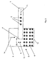
- Figure 1 shows an embodiment of the device according to the invention, in which the aligning belt is moved in two directions.
- Figure 2 shows an embodiment of the device according to the invention, in which the portioning belt is moved in two directions.
- FIG. 3 shows a further embodiment of the device according to the invention, in which the portioning belt is moved in two directions.
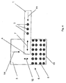
- Figure 4 shows an embodiment of the device according to the invention, in which the transfer edge of the aligning belt in the transport direction and the portioning belt is moved transversely thereto.
- Figure 5 shows an embodiment of the device according to the invention, in which the aligning belt is moved transversely to the transport direction and the Portionierband in the transport direction of the aligning belt.
- FIG. 6 shows an embodiment of the device according to the invention with a means by which the products can be arranged on the line-up belt relative to the center track.
- Figure 7 shows an embodiment of the device according to the invention with two Aukehbändem.
- Figure 8 shows a further embodiment of the device according to the invention with two Aukehbändem.
- FIG. 9 shows an embodiment of the device according to the invention with two portioning belts.
- FIG. 10 shows a device according to the invention, in which the portioning belt is also an insert belt.
- Figure 11 shows products in a uniform row.
- Figure 12 shows products in an uneven series.
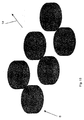
- Figure 13 shows shingled products.
- Figure 14 shows shingled products.
- Figure 15 shows terraced products.
- Figure 16 shows stacked products.
- Figure 17 shows cross-linked products.
- Figure 18 shows shingled products without overlap.
- Figure 19 shows staggered products.
- Figure 1 shows an embodiment of the device according to the invention with a line-up belt 1 and a portioning belt 3.
- the products 2 (only three shown) are transported with the Auokhhband.
- the transport direction is symbolized by the arrow 11.
- the distance of the products 2 on the line-up belt 1 does not have to be constant in the conveying direction 11.
- the line-up belt has a machine frame (not shown) in which a conventional endless belt is arranged.
- the endless belt is driven by a servo motor at a constant speed.
- the line-up belt has a transfer edge 4, at which the products 2 are dropped onto the portioning belt 3.
- the transfer edge is movable both in and against the transport direction 11 and transversely to the transport direction 11 of the aligning belt relative to the Portionierband, which is symbolized by the double arrows 7 and 8 respectively.
- the transfer edge 4 is slidably mounted relative to the machine frame in a guide, not shown, whereby the conveyor belt is extended or shortened.
- the drive of the transfer edge is done by a servomotor.
- the discharge of the products 2 can be done by a fast return stroke, so that the tilting effect of the products during the parabolic trajectory is reduced.
- the expert understands that for the line-up a band length compensation must be provided so that on the one hand a sufficient tape length is available, on the other hand, the band is always taut.
- the movement of the transfer edge 4 transversely to the transport direction 8 is achieved by a movement of the entire Auokbandes 1, which is effected by a servo motor.
- the person skilled in the art understands that the movement of the aligning belt in the transport direction of the products can also be achieved by shifting the entire aligning belt. Since the two movements can be superimposed, any points in a plane can be approached.
- the movement of the transfer edge 4 of the aligning belt 1 is dimensioned such that the products 2 can be deposited at all desired points of the portioning belt 3, taking into account the throwing parabola.
- the portioning belt 3 in the present case is also designed as a conveyor belt, which transports the products cyclically in the direction symbolized by the arrow 14 as soon as a format configuration 5, which in the present case consists of six juxtaposed portions 6 in two rows, on the Portionierband is stored.
- the skilled person understands that this function can also be used for portion and / or format formation.
- the conveyor belt is driven by a servomotor.
- the device according to the invention has a control which controls the position of the transfer edge such that any portion images and formats can be produced on the portioning belt.
- the controller also controls the feed 14.
- the portioning belt 3 With the portioning belt 3, the products can not only be transported further but also be placed in packaging.
- the portioning belt 3 is then also an insert belt at the same time.
- the end 15 of the portioning belt is also displaceably mounted on the frame (not shown) of the portioning belt 3.
- the portions 6 can then be inserted with a quick retraction of the end 15 with the belt stopped in the packaging.
- the insertion of the portions 6 in packages is also controlled by the above-mentioned controller. On the insertion of products in packaging is discussed in more detail in the notes to Figure 10.
- the portions 6 can not be a product but a plurality of products that have been configured into one portion. This portion may already have been handed over to the aligning belt and / or generated by the movement of the transfer edge. Possible portions are shown in FIGS. 11-19.
- the device according to the invention has a photocell (not shown) which detects at least the position of the products 2 on the aligning belt in the conveying direction. The further path and the speed of the respective product 2 or of the respective portion 6 on the line-up and portioning belt is then precisely calculated, so that the device according to the invention knows exactly at each point in time where the respective product is and what speed it has.
- the movement of the transfer edge makes it possible to divide a single-row product stream into a multi-column (six-column) product stream.
- the embodiment of the device according to the invention in FIG. 2 essentially corresponds to the embodiment of the device according to FIG. 1, except that in FIG. 2 the portioning belt is moved in two directions.
- the comments on Figure 1 thus apply analogously.
- the portioning belt 3 is designed as an endless belt, which is guided in a machine frame (not shown).
- the movement of the portioning belt relative to the transfer edge and in direction 10 is effected by a reciprocating motion of the endless belt relative to the machine frame.
- the movement of the portioning belt relative to the transfer edge and in the direction 9 is effected by a displacement of the entire machine frame.
- the movements of the Portionierbandes 3 relative to the transfer edge 4 is carried out with two servomotors (not shown).
- FIG. 3 shows a further embodiment of the device according to the invention, in which the portioning belt is moved in two directions.
- This embodiment of the present invention essentially corresponds to the embodiment according to FIG. 2, except that in the present example the aligning belt 1 is arranged parallel to the portioning belt 3.
- the comments on the figures 1 and 2 thus apply analogously.
- Figure 4 shows an embodiment of the device according to the invention, in which the transfer edge of the aligning belt in and / or against the transport direction and the Portionierband is moved transversely thereto.
- the movement of the transfer edge 4 is preferably carried out in that the transfer edge 4 (not shown) of the Auokbandes 1 is movably mounted on the machine frame and is pushed by a servo motor within the guide back and forth.
- the Portionierband is preferably designed as an endless belt, which is guided in a machine frame and is driven by a servo motor.
- the movement of the portioning belt 3 is preferably achieved by a reciprocating movement of the endless belt.
- This embodiment has the advantage that any portion images 6 and format configurations 5 can be placed on the portioning belt 3 without the line-up belt or the portioning belt having to be moved in its entirety.
- the comments on the figures 1 - 3 apply analogously.
- Figure 5 shows an embodiment of the device according to the invention, in which the transfer edge of the aligning belt is moved transversely to the transport direction and the Portionierband in and / or against the transport direction of the Auokbandes. Also in this embodiment, therefore, the movements in and across the transport direction of the aligning belt are divided between the two units. Moreover, the comments on the figures 1 - 4 apply analogously.
- Figure 6 shows an embodiment of the device according to the invention, with a means 12, with which the products on the aligning belt 1 relative to the center track 13 can be lined up.
- the products 2 are distributed relative to the center track 13 on the line-up belt 1 such that the desired portion images 6 or format configurations 5 take place only by a movement of the transfer edge 4 of the aligning belt relative to the portioning belt and / or the portioning belt 3 relative to the transfer edge 4.
- a circle can be placed on the Portionierband when the products 2 are arranged sinusoidally on the line-up.
- the comments on the figures 1-5 apply analogously.
- Figures 7 and 8 show an embodiment of the device according to the invention with two Aukab Sn 1, which are designed in the present case as endless belts which are guided in machine frame.
- the endless belts are driven by a servomotor.
- the transfer edge 4 is arranged in each case in a guide (not shown) displaceable on the machine frame, wherein the displacement of the transfer edge also takes place by a servo motor.
- Both straightening belts can be operated completely independently of each other. This applies both to the drives of the endless belts and to the displacement of the transfer edge.
- This embodiment of the present invention is advantageous when several product series for delivery to a storage system or in an insertion station must be provided. For the rest, reference is made to the comments on Figure 1.
- FIG. 9 shows a further embodiment of the device according to the invention with two portioning belts 3. This solution is of particular interest when, for example, two packaging machines are to be charged with the same products, wherein the portion configurations 6 and the formats 5 can each be different.
- FIG. 10 shows a system according to the invention, comprising a device according to the invention and a cyclically operating packaging machine, of which only the insertion station 16 is shown.
- the device according to the invention has a line-up belt 1 and a portioning belt 3 arranged at right angles thereto.
- the line-up belt 1 is a single-band continuous belt whose end 4 is again designed to be movable in the manner already described above.
- the portioning belt 3 is likewise designed as an endless belt.
- the band end 15 is also designed as a movable band end in the sense of a retraction / shuttle belt.
- the packaging trays 18 are only shown schematically.
- the double arrow 7 symbolizes the reciprocating movement of the transfer edge 4 and the arrow 10 the movement of the portioning belt 3 relative to the transfer edge 4.
- the double arrow 19 indicates the reciprocating movement of the transfer edge 15.
- the products 2 of FIG the Auokband 1 on the trained as an insert tape Portionierband where they can be stored by the movable training of the transfer edge 4, for example, in different order, as a stack or shingled as portions 6 in the format 5.
- a format 5 consists in the present case of three rows and three columns, wherein the number of rows of the number of transverse to the transport direction 17 adjacent packaging troughs 18 and the number of columns corresponds to the advance of the packaging troughs at one stroke.
- the portioning belt 3 then conveys these portions 6 to the loading station 16.
- the portioning belt 3 deposits or ejects the portions 6 into the free packaging troughs in the loading station 16.
- This is possible in this example in different variations, since the band end 15 is also designed to be movable.
- the portioning belt 3 can also be divided into several strips. In this case, it is then possible to independently form their tape ends as a retraction / shuttle belt. Both bands have a band compensation 20.
- the device according to the invention consists of a line-up belt 1 and a portioning belt 3.
- the line-up belt 1 is parallel to the packaging machine with the loading station 16 and the portioning belt 3 transversely to the conveyor belt 1 and to the loading station 16 of the packaging machine.
- the line-up belt 1 conveys the series of incoming products or portions to the portioning belt 3. This in turn then transports the products 2 as portions 6 and arranged in a specific format 5 to the loading station 16 of the packaging machine.
- both bands 1, 3 are constructed the same as endless belts. They differ only in their width in the selected embodiment.
- each of the two conveyor belts 1, 3 is a servo motor for driving the conveyor belt and a servo motor for driving the movement of the band ends 4, 15.
- this embodiment is also referred to as a shuttle belt.
- the reference numeral 20 indicates a length compensating device which enables rapid compensation or provision of conveyor belt upon a change in the effective length of the conveyor belt. From the line-up belt 1, the products 2 arriving in series are dropped onto the portioning belt 3 at the same belt speed via the control of the belt retraction. Depending on the format configuration of the packaging machine (in the conveying direction of the packaging troughs 18), this may be one, two, three or more discharge points, in the present case being three.
- a quick return stroke of the transfer edge 4 while reaching the discharge position thereby causes a reduction of the tilting effect during the parabolic flight path.
- the portioning belt 3 continues to cycle by a calculated measure, when a series of products 2 has been transferred from the line-up belt 1 to the portioning belt. This means that the belt feed of the second conveyor belt 3 takes place step by step. This feed-forward then generates the required format configuration transverse to the transport direction of the packaging machine.
- the portioning belt continues to pace by another calculated amount and a new format is filed. In the present example, two formats are completely stored on the portioning belt. In a third format, the first row is being stored.
- both bands are designed as a retraction / shuttle belt.
- the two conveyor belts are at right angles to each other.
- the Formatkonfguration can be stored in the program, that is, a change in the format division requires only a switch to another program, without causing any components of the packaging line must be changed in position.
- a detection means at the beginning of the line-up belt 1
- the device according to the invention therefore knows at any time where the respective product 2 or the respective portion 6 is located and what speed it currently has. This information is particularly important for the restart of the device according to the invention after an operational stop, because the device according to the invention can be restarted automatically.
- Products that are located after the stop on the device according to the invention need not be removed. At least the position of the products 2 in the conveying direction 11 is determined with the detection means. If an offset of the products relative to the center axis or any other longitudinal axis of the aligning belt is determined with the detection means, this information can be used to compensate for the offset with a corresponding movement of the portioning belt, so that on the Portionierband the desired portion image or the desired format configuration is generated.
- the selected arrangement of the bands 1, 3 to each other, the use of servo drives and the vote of the position of the transfer edge 4 relative to the Portionierband and the movement of the Portionierbandes 3 relative to the transfer edge 4 allows the creation of arbitrary portion images 6 and format configurations 5, the example in Figures 11-19 are shown.
- the distance between the products 2 on the aligning belt may vary.
- Figure 11 shows six portions 6 in a uniform row. There are two rows shown. The portions 6 are transported in the direction shown by the arrow 14 on the portioning belt (not shown).
- the format can be on or off be double row; ie, either one or two rows are deposited during a cycle in the loading station of a packaging machine.
- Figure 12 shows three portions 6 in an uneven row. There are two rows shown. The portions 6 are transported in the direction shown by the arrow 14 on the portioning belt (not shown).
- the format can be one or two rows; ie, either one or two rows are deposited during a cycle in the loading station of a packaging machine.
- Figure 13 shows two forward shingled portions 6 in a row.
- a row is generated in which the portion construction from left to right or based on the transport direction of the aligning belt takes place from back to front.
- the portioning tape stands still during this.
- the portions 6 are transported in the direction shown by the arrow 14 on the portioning belt (not shown).
- the format can be one or two rows; ie, either one or two rows are deposited during a cycle in the loading station of a packaging machine.
- Figure 14 shows two shingled portions 6 in a row.
- a row is generated in which the portion construction from right to left or based on the transport direction 11 of the aligning belt takes place from front to back.
- the portioning tape stands still during this.
- the portions 6 are transported in the direction shown by the arrow 14 on the portioning belt (not shown).
- the format can be one or two rows; ie, either one or two rows are deposited during a cycle in the loading station of a packaging machine.
- Figure 15 shows two terraced portions 6 in a row.
- a row is produced, in which only the two products lying below are deposited, and then in each case a product is placed thereon.
- the portioning belt stands still during the filing of a series.
- the portions 6 are shown in the direction indicated by the arrow 14 Direction transported on the Portionierband (not shown).
- the format can be one or two rows; ie, either one or two rows are deposited during a cycle in the loading station of a packaging machine.
- Figure 16 shows three stacked portions 6 in a row.
- a stack 6 is produced in which three products 2 each are deposited at one location on the portioning belt.
- the portioning belt stands still during the filing of a series. There are two rows shown.
- the portions 6 are transported in the direction shown by the arrow 14 on the portioning belt (not shown).
- the format can be one or two rows; ie, either one or two rows are deposited during a cycle in the loading station of a packaging machine.
- FIG. 17 shows two transverse shingled portions 6 in a row.
- a portion 6 is produced in which three products 2 each are deposited at one location on the portioning belt.
- the Portionierband transports the product just stored by one clock before the next product is stored, the two portions 6 of a row, however, are preferably created in parallel.
- the portions 6 are transported in the direction shown by the arrow 14 on the portioning belt (not shown).
- the format can be one or two rows; ie, either one or two rows are deposited during a cycle in the loading station of a packaging machine.
- Figure 18 shows three cross-shingled portions 6 without overlapping in a row.
- a portion 6 is produced, in which a product 2 is deposited on the portioning belt.
- the Portionierband transports the product just stored by one clock before the next product is stored, the three portions 6 of a row, however, are preferably created in parallel. It is a series shown.
- the portions 6 are transported in the direction shown by the arrow 14 on the portioning belt (not shown).
- Figure 19 shows three staggered portions 6 without overlapping in a row.
- a portion 6 is produced, in which a product 2 is deposited on the portioning belt.
- the Portionierband transports the product just stored by one clock before the next product is stored, the three portions 6 of a row, however, are preferably created in parallel. It is a series shown.
- the portions 6 are transported in the direction shown by the arrow 14 on the portioning belt (not shown).
Landscapes
- Engineering & Computer Science (AREA)
- Mechanical Engineering (AREA)
- Attitude Control For Articles On Conveyors (AREA)
- Vehicle Body Suspensions (AREA)
- Paper (AREA)
- Body Structure For Vehicles (AREA)
- Tents Or Canopies (AREA)
- Mechanical Treatment Of Semiconductor (AREA)
Applications Claiming Priority (2)
| Application Number | Priority Date | Filing Date | Title |
|---|---|---|---|
| DE10201182A DE10201182A1 (de) | 2002-01-14 | 2002-01-14 | Positioniersystem |
| EP03729241A EP1472162B1 (fr) | 2002-01-14 | 2003-01-10 | Dispositif pour déposer des objets à un endroit précis |
Related Parent Applications (1)
| Application Number | Title | Priority Date | Filing Date |
|---|---|---|---|
| EP03729241A Division EP1472162B1 (fr) | 2002-01-14 | 2003-01-10 | Dispositif pour déposer des objets à un endroit précis |
Publications (2)
| Publication Number | Publication Date |
|---|---|
| EP1683746A2 true EP1683746A2 (fr) | 2006-07-26 |
| EP1683746A3 EP1683746A3 (fr) | 2006-08-02 |
Family
ID=7712119
Family Applications (2)
| Application Number | Title | Priority Date | Filing Date |
|---|---|---|---|
| EP06005477A Withdrawn EP1683746A3 (fr) | 2002-01-14 | 2003-01-10 | Dispositif et procédé pour doser et déposer en ordre des produits |
| EP03729241A Revoked EP1472162B1 (fr) | 2002-01-14 | 2003-01-10 | Dispositif pour déposer des objets à un endroit précis |
Family Applications After (1)
| Application Number | Title | Priority Date | Filing Date |
|---|---|---|---|
| EP03729241A Revoked EP1472162B1 (fr) | 2002-01-14 | 2003-01-10 | Dispositif pour déposer des objets à un endroit précis |
Country Status (9)
| Country | Link |
|---|---|
| US (1) | US7413070B2 (fr) |
| EP (2) | EP1683746A3 (fr) |
| AT (1) | ATE341506T1 (fr) |
| AU (1) | AU2003235805A1 (fr) |
| DE (2) | DE10201182A1 (fr) |
| DK (1) | DK1472162T3 (fr) |
| ES (1) | ES2276064T3 (fr) |
| NO (1) | NO20045188L (fr) |
| WO (1) | WO2003057602A1 (fr) |
Cited By (4)
| Publication number | Priority date | Publication date | Assignee | Title |
|---|---|---|---|---|
| WO2008034482A1 (fr) * | 2006-09-20 | 2008-03-27 | Weber Maschinenbau Gmbh Breidenbach | Dispositif et procédé pour le transfert d'un groupe de produits d'un convoyeur d'entrée à un convoyeur de sortie |
| DE102013226783A1 (de) * | 2013-12-19 | 2015-06-25 | Loesch Verpackungstechnik Gmbh | Verfahren und Vorrichtung zum Fördern und Gruppieren von stückigen Produkten |
| EP2030898B2 (fr) † | 2007-08-28 | 2016-09-28 | Multitec Holdings GmbH | Procédé pour le fonctionnement d'un convoyeur d'alimentation |
| EP2910476B1 (fr) | 2014-02-24 | 2017-06-28 | MultiTec Holdings GmbH | Dispositif de transport de produits alimentaires |
Families Citing this family (37)
| Publication number | Priority date | Publication date | Assignee | Title |
|---|---|---|---|---|
| US8479912B2 (en) * | 2004-04-29 | 2013-07-09 | Span Tech Llc | Matrix sorter system with transpositor conveyor |
| CA2577771C (fr) * | 2004-08-20 | 2014-04-01 | Formax, Inc. | Appareil de chargement pour piles de produits alimentaires |
| US20060248636A1 (en) * | 2005-05-06 | 2006-11-09 | Brill Hygienic Products, Inc. | Automated toilet seat system with quick disconnect cable |
| GB2426497B (en) * | 2005-05-26 | 2008-03-26 | Quin Systems Ltd | Product handling |
| US7921982B2 (en) * | 2007-07-24 | 2011-04-12 | Douglas Machine, Inc. | Methods and apparatus for handling products |
| IT1394385B1 (it) * | 2009-06-22 | 2012-06-15 | Teknoweb S R L | Sistema perfezionato per raggruppare ed espellere da una linea di produzione principale pacchetti multistrato di salviettine monouso. |
| IT1402775B1 (it) * | 2010-11-16 | 2013-09-18 | Tecnema Societa A Responsabilita Limitata | Macchina per il trasferimento di manufatti ceramici tra linee di movimentazione |
| IT1404664B1 (it) | 2010-12-22 | 2013-11-29 | Grasselli | Apparecchiatura per deposizione in contenitori di alimenti affettati |
| EP2478771B1 (fr) | 2011-01-25 | 2015-04-08 | GEA Food Solutions Bakel B.V. | Chaîne de production d'aliments |
| MX364365B (es) * | 2012-02-03 | 2019-04-24 | Span Tech Llc | Sistemas de ordenamiento y metodos relacionados. |
| CN102633007B (zh) * | 2012-04-23 | 2014-09-17 | 北京海力捷特机械设备有限公司 | 一种软包装全自动装箱机 |
| EP2749512B2 (fr) * | 2012-12-28 | 2023-08-16 | Gebo Packaging Solutions Italy SRL | Unité et procédé de formation d'une couche de lots de groupes d'articles |
| DE102013002754A1 (de) * | 2013-02-19 | 2014-08-21 | Heidelberger Druckmaschinen Ag | Vorrichtung zum Auslegen von in einem Produktstrom zugeführten Druckereiprodukten in zwei voneinander getrennten Stapeln |
| DE102014104387A1 (de) | 2014-03-28 | 2015-10-01 | Textor Maschinenbau GmbH | Vorrichtung zur Verarbeitung von Lebensmittelprodukten |
| CN104925504A (zh) * | 2015-06-10 | 2015-09-23 | 苏州米达思精密电子有限公司 | 一种补强片自动送料定位设备 |
| EP3683155B1 (fr) * | 2015-09-08 | 2021-11-10 | GEA Food Solutions Germany GmbH | Dispositif d'introduction doté d'une bande de division en portions |
| US9802768B2 (en) * | 2015-10-29 | 2017-10-31 | The Procter & Gamble Company | Apparatus for reorienting and/or stacking products |
| DE202016000757U1 (de) | 2016-02-03 | 2016-03-10 | Multivac Sepp Haggenmüller Se & Co. Kg | Tiefziehverpackungsmaschine |
| CN109863089B (zh) * | 2016-10-07 | 2021-06-29 | 哈斯塔玛特包装技术有限公司 | 用于扁平产品的份包装的方法和装置 |
| IT201600110158A1 (it) * | 2016-11-02 | 2018-05-02 | Grasselli S P A | Macchina per la deposizione di alimenti affettati in contenitori |
| IT201600120561A1 (it) * | 2016-11-29 | 2018-05-29 | Azionaria Costruzioni Acma Spa | Gruppo alimentatore di prodotti alimentari |
| DE102017120823A1 (de) * | 2017-09-08 | 2019-03-14 | Vemag Maschinenbau Gmbh | Verfahren und Vorrichtung zum gruppierten Anordnen und Ausrichten und Verpacken von individuellen Lebensmittel-Produkten, insbesondere Patty-Stapel |
| DE102017130735A1 (de) * | 2017-12-20 | 2019-06-27 | Delphi Salesconsulting Ag | Vorrichtung zur automatisierten Veränderung der Zusammensetzung eines Gemenges |
| US10882705B2 (en) | 2017-12-27 | 2021-01-05 | The Procter & Gamble Company | Method for transferring and/or stacking products |
| US10899562B2 (en) | 2017-12-27 | 2021-01-26 | The Procter & Gamble Company | Apparatus for transferring and/or stacking products |
| IL257582B (en) * | 2018-02-18 | 2021-08-31 | Velox Puredigital Ltd | Conveyors interfacing system and method |
| US11134712B2 (en) | 2018-08-08 | 2021-10-05 | Mp Equipment Llc | Adjustable breading machine and method of operation |
| NL2024890B1 (en) * | 2020-02-12 | 2021-09-15 | Mde Automation B V | System for transporting and delivering piece goods. |
| WO2022006157A1 (fr) * | 2020-06-30 | 2022-01-06 | Fulfil Solutions, Inc. | Systèmes et procédés de manipulation d'articles |
| AU2021456544A1 (en) * | 2021-07-22 | 2024-01-25 | Confirmed Automation Systems Inc. | Mushroom packing apparatus |
| DE102022213156A1 (de) | 2021-12-09 | 2023-06-15 | Gea Food Solutions Germany Gmbh | Rückzugstransportband mit einem Motor |
| JP7842347B2 (ja) * | 2022-08-12 | 2026-04-08 | 澁谷工業株式会社 | 集積装置 |
| EP4328157A1 (fr) * | 2022-08-22 | 2024-02-28 | Rotzinger AG | Station de distribution de produits dotée de plusieurs bandes de distribution |
| DE102022121774A1 (de) * | 2022-08-29 | 2024-02-29 | Multivac Sepp Haggenmüller Se & Co. Kg | Verfahren zum automatischen Einhalten einer vorgegebenen Portions-Anordnung in einer Tray-Mulde sowie hierfür geeignete Verpackungs-Vorrichtung |
| JP2024066789A (ja) * | 2022-11-02 | 2024-05-16 | 株式会社イシダ | 箱詰装置 |
| JP2024120240A (ja) * | 2023-02-24 | 2024-09-05 | 株式会社イシダ | 物品搬送装置 |
| DE102023110703A1 (de) | 2023-04-26 | 2024-10-31 | Multivac Sepp Haggenmüller Se & Co. Kg | Verfahren zum Betreiben einer Verpackungslinie sowie Verpackungslinie |
Family Cites Families (23)
| Publication number | Priority date | Publication date | Assignee | Title |
|---|---|---|---|---|
| US3106280A (en) * | 1958-12-05 | 1963-10-08 | Baker Perkins Inc | Transfer of articles between moving conveyor means |
| DE1188013B (de) * | 1964-07-18 | 1965-03-04 | Werner & Pfleiderer | Vorrichtung zum UEbertragen von Teigstuecken |
| US3406384A (en) | 1966-08-26 | 1968-10-15 | Robert L. Hartman | Fire detector and preventer system |
| BE793664A (fr) * | 1972-01-05 | 1973-05-02 | Dixie Union Verpackungen Gmbh | Dispositif de transport et de dechargement |
| DE2516583A1 (de) * | 1975-04-16 | 1976-10-28 | Waldner Kg H | Beschickungsvorrichtung fuer verpackungsmaschinen |
| EP0104142A3 (fr) * | 1982-09-16 | 1985-05-02 | Hollymatic AG Ingenbohl | Dispositif pour déposer des objets à un endroit précis |
| CH657829A5 (de) * | 1982-12-17 | 1986-09-30 | Sig Schweiz Industrieges | Vorrichtung zum umordnen von scheibenfoermigen gegenstaenden, z.b. biskuits. |
| GB8431291D0 (en) * | 1984-12-12 | 1985-01-23 | Thurne Eng Co Ltd | Conveyor |
| ATE41399T1 (de) * | 1985-08-20 | 1989-04-15 | Rheon Automatic Machinery Co | Verfahren zum ordnen und befoerdern von produktreihen. |
| DE3876206D1 (de) * | 1987-10-16 | 1993-01-07 | Hauni Werke Koerber & Co Kg | Verfahren und vorrichtung zum gruppenweisen verpacken von einzelpackungen. |
| US5088912A (en) * | 1990-06-01 | 1992-02-18 | Raque Food Systems, Inc. | Dough processing and conveyor system |
| CH683418A5 (de) * | 1990-06-06 | 1994-03-15 | Rotzinger Ag | Vorrichtung um in unregelmässiger Folge eintreffende Gegenstände abzulegen. |
| DE4243689A1 (de) * | 1992-12-18 | 1994-06-23 | Hans Dentler | Regeleinrichtung für einen Förderstrom |
| US5383760A (en) * | 1993-11-01 | 1995-01-24 | Ohmstede-Cawley, Ltd. | Apparatus and method for container pattern-forming and palletizing |
| DE19516807C2 (de) * | 1995-05-08 | 1998-01-15 | Siegfried Mache | Vorrichtung zum Aufnehmen von kontinuierlich in einer Förderbahn einzeln hintereinander zugeführten Gegenständen und zum gruppenweisen Bereitstellen der Gegenstände |
| JP2853032B2 (ja) * | 1996-03-30 | 1999-02-03 | レオン自動機株式会社 | 食品等の移載方法および装置 |
| US5810149A (en) | 1996-11-26 | 1998-09-22 | Formax, Inc. | Conveyor system |
| DE19752908A1 (de) * | 1997-11-28 | 1999-06-02 | Peter Nagler | Verfahren zur automatisierten Gruppierung von Objekten |
| IT1301696B1 (it) * | 1998-06-12 | 2000-07-07 | Cml Handling Technology S P A | Metodo ed apparecchiatura per il caricamento automatico di piu'oggetti ordinati, sulla stessa unita' di una macchina smistatrice |
| DE19963398A1 (de) * | 1999-12-28 | 2001-07-05 | Biforce Anstalt Vaduz | Fördersystem |
| ATE382565T1 (de) * | 2001-08-01 | 2008-01-15 | Formax Inc | Förderer und system zur ablage von gegenständen auf einen förderer |
| SI1461359T1 (sl) | 2002-01-18 | 2007-06-30 | Pf Medicament | Nova anti IGF-IR protitelesa in njihova uporaba |
| US7021450B2 (en) * | 2002-04-17 | 2006-04-04 | Kraft Foods Holdings, Inc. | Device and method to correct uneven spacing of successive articles |
-
2002
- 2002-01-14 DE DE10201182A patent/DE10201182A1/de not_active Withdrawn
-
2003
- 2003-01-10 EP EP06005477A patent/EP1683746A3/fr not_active Withdrawn
- 2003-01-10 DE DE50305253T patent/DE50305253D1/de not_active Revoked
- 2003-01-10 AT AT03729241T patent/ATE341506T1/de not_active IP Right Cessation
- 2003-01-10 DK DK03729241T patent/DK1472162T3/da active
- 2003-01-10 AU AU2003235805A patent/AU2003235805A1/en not_active Abandoned
- 2003-01-10 ES ES03729241T patent/ES2276064T3/es not_active Expired - Lifetime
- 2003-01-10 EP EP03729241A patent/EP1472162B1/fr not_active Revoked
- 2003-01-10 WO PCT/EP2003/000179 patent/WO2003057602A1/fr not_active Ceased
- 2003-01-10 US US10/501,413 patent/US7413070B2/en not_active Expired - Lifetime
-
2004
- 2004-11-26 NO NO20045188A patent/NO20045188L/no not_active Application Discontinuation
Cited By (10)
| Publication number | Priority date | Publication date | Assignee | Title |
|---|---|---|---|---|
| WO2008034482A1 (fr) * | 2006-09-20 | 2008-03-27 | Weber Maschinenbau Gmbh Breidenbach | Dispositif et procédé pour le transfert d'un groupe de produits d'un convoyeur d'entrée à un convoyeur de sortie |
| EP2030898B2 (fr) † | 2007-08-28 | 2016-09-28 | Multitec Holdings GmbH | Procédé pour le fonctionnement d'un convoyeur d'alimentation |
| DE102013226783A1 (de) * | 2013-12-19 | 2015-06-25 | Loesch Verpackungstechnik Gmbh | Verfahren und Vorrichtung zum Fördern und Gruppieren von stückigen Produkten |
| US10259660B2 (en) | 2013-12-19 | 2019-04-16 | Loesch Verpackungstechnik Gmbh | Method and device for conveying and grouping fragmented products |
| EP2910476B1 (fr) | 2014-02-24 | 2017-06-28 | MultiTec Holdings GmbH | Dispositif de transport de produits alimentaires |
| US10457433B2 (en) | 2014-02-24 | 2019-10-29 | Provisur Technologies Inc. | Conveyor device for conveying food products |
| US10807748B2 (en) | 2014-02-24 | 2020-10-20 | Provisur Technologies, Inc. | Conveyor device for conveying food products |
| US11225347B2 (en) | 2014-02-24 | 2022-01-18 | Provisur Technologies, Inc. | Conveyor device for conveying food products |
| US11554887B2 (en) | 2014-02-24 | 2023-01-17 | Provisur Technologies, Inc. | Conveyor device for conveying food products |
| US11845577B2 (en) | 2014-02-24 | 2023-12-19 | Provisur Technologies, Inc. | Conveyor device for conveying food products |
Also Published As
| Publication number | Publication date |
|---|---|
| EP1472162B1 (fr) | 2006-10-04 |
| ES2276064T3 (es) | 2007-06-16 |
| EP1683746A3 (fr) | 2006-08-02 |
| EP1472162A1 (fr) | 2004-11-03 |
| ATE341506T1 (de) | 2006-10-15 |
| WO2003057602A1 (fr) | 2003-07-17 |
| AU2003235805A1 (en) | 2003-07-24 |
| NO20045188L (no) | 2004-11-26 |
| US7413070B2 (en) | 2008-08-19 |
| DE50305253D1 (de) | 2006-11-16 |
| US20060131131A1 (en) | 2006-06-22 |
| DE10201182A1 (de) | 2003-07-24 |
| DK1472162T3 (da) | 2007-02-05 |
Similar Documents
| Publication | Publication Date | Title |
|---|---|---|
| EP1472162B1 (fr) | Dispositif pour déposer des objets à un endroit précis | |
| EP2792626B1 (fr) | Procédé et dispositif de regroupement | |
| EP2836447B1 (fr) | Dispositif et procédé de transport de produits en morceaux | |
| EP2415695B1 (fr) | Dispositif et procédé pour regrouper des articles à faire emballer et coulisses de tiroir profilées pour appliquer ce procédé | |
| DE69302168T2 (de) | Verfahren und vorrichtung zur manipulation eines produktstromes | |
| DE69102859T2 (de) | Pufferspeicher. | |
| EP2799348B1 (fr) | Procédé de regroupement d'articles en un faisceau d'articles et dispositif de regroupement et machine d'emballage doté d'un tel dispositif | |
| EP2097324B1 (fr) | Procede pour commander le transfert d'une pile de produits dans une machine d'emballage | |
| DE2702041B2 (de) | Vorrichtung zum wahlweisen Aufteilen einer Reihe von einzelnen gewickelten Rollen aus Folien o.dgl. von einem Zuförderer über einen Zwischenförderer an eine Anzahl von Verteilförderern | |
| EP0311830A1 (fr) | Procédé et dispositif pour l'emballage de groupes de paquets solitaires | |
| EP3339221A2 (fr) | Dispositif et procédé destinés à la manipulation de produits | |
| EP3539910A1 (fr) | Système de bande transporteuse pour mettre en place des produits dans un agencement prédéfini | |
| DE102022130350A1 (de) | Verfahren zum Betreiben einer Verpackungslinie sowie hierfür geeignete Verpackungslinie | |
| DE2030165C3 (de) | Vorrichtung zum Bilden mehrlagiger Zigarettengruppen | |
| EP3502017A1 (fr) | Dispositif et procédé de manipulation des portions des denrées alimentaires à l'aide d'un agencement rotatif | |
| EP3025587B1 (fr) | Dispositif et procédé destinés au transfert de portions de saucisses | |
| DE102010053040A1 (de) | Vorrichtung und Verfahren zum Gruppieren von Gegenständen | |
| DE4442586B4 (de) | Vorrichtung zum Verteilen von Gefäßen | |
| DE4330427C2 (de) | Verfahren und Vorrichtung zur Stapelbildung flacher Warenstücke, insbesondere zum Verpacken von Keksen | |
| DE4439728A1 (de) | Vorrichtung zum Befördern und Gruppieren von Gegenständen | |
| EP0591099B1 (fr) | Procédé et dispositif pour fabriquer des piles de produits en papier liées | |
| EP3068713B1 (fr) | Procédé et dispositif de transport et de regroupement de produits en morceaux | |
| EP3693299B1 (fr) | Dispositif de transport continu des marchandises transportées et procédé de transport continu des marchandises | |
| DE602004000046T2 (de) | Anordnungsvorrichtung für feste Gegenstände | |
| EP2862683A1 (fr) | Dispositif et procédé destinés au traitement de produits alimentaires |
Legal Events
| Date | Code | Title | Description |
|---|---|---|---|
| PUAI | Public reference made under article 153(3) epc to a published international application that has entered the european phase |
Free format text: ORIGINAL CODE: 0009012 |
|
| PUAL | Search report despatched |
Free format text: ORIGINAL CODE: 0009013 |
|
| AC | Divisional application: reference to earlier application |
Ref document number: 1472162 Country of ref document: EP Kind code of ref document: P |
|
| AK | Designated contracting states |
Kind code of ref document: A2 Designated state(s): AT BE BG CH CY CZ DE DK EE ES FI FR GB GR HU IE IT LI LU MC NL PT SE SI SK TR |
|
| AK | Designated contracting states |
Kind code of ref document: A3 Designated state(s): AT BE BG CH CY CZ DE DK EE ES FI FR GB GR HU IE IT LI LU MC NL PT SE SI SK TR |
|
| 17P | Request for examination filed |
Effective date: 20070202 |
|
| AKX | Designation fees paid |
Designated state(s): AT BE BG CH CY CZ DE DK EE ES FI FR GB GR HU IE IT LI LU MC NL PT SE SI SK TR |
|
| RAP1 | Party data changed (applicant data changed or rights of an application transferred) |
Owner name: CFS BUEHL GMBH |
|
| 17Q | First examination report despatched |
Effective date: 20090116 |
|
| GRAP | Despatch of communication of intention to grant a patent |
Free format text: ORIGINAL CODE: EPIDOSNIGR1 |
|
| RTI1 | Title (correction) |
Free format text: METHOD FOR CREATING ARBITRARY PORTIONS AND FORMATS |
|
| STAA | Information on the status of an ep patent application or granted ep patent |
Free format text: STATUS: THE APPLICATION IS DEEMED TO BE WITHDRAWN |
|
| 18D | Application deemed to be withdrawn |
Effective date: 20091201 |