EP1684244A2 - Verkaufsautomat - Google Patents
Verkaufsautomat Download PDFInfo
- Publication number
- EP1684244A2 EP1684244A2 EP06009045A EP06009045A EP1684244A2 EP 1684244 A2 EP1684244 A2 EP 1684244A2 EP 06009045 A EP06009045 A EP 06009045A EP 06009045 A EP06009045 A EP 06009045A EP 1684244 A2 EP1684244 A2 EP 1684244A2
- Authority
- EP
- European Patent Office
- Prior art keywords
- elevator
- cabinet
- shelves
- vending machine
- shelf
- Prior art date
- Legal status (The legal status is an assumption and is not a legal conclusion. Google has not performed a legal analysis and makes no representation as to the accuracy of the status listed.)
- Withdrawn
Links
- 238000000034 method Methods 0.000 claims description 13
- 238000004891 communication Methods 0.000 claims description 2
- 238000012545 processing Methods 0.000 claims description 2
- 235000013361 beverage Nutrition 0.000 abstract description 131
- 230000007246 mechanism Effects 0.000 abstract description 80
- 230000004913 activation Effects 0.000 abstract description 3
- 230000000712 assembly Effects 0.000 description 29
- 238000000429 assembly Methods 0.000 description 29
- 230000033001 locomotion Effects 0.000 description 12
- 238000003860 storage Methods 0.000 description 8
- 235000014676 Phragmites communis Nutrition 0.000 description 6
- 230000005484 gravity Effects 0.000 description 5
- 238000004804 winding Methods 0.000 description 5
- 230000003993 interaction Effects 0.000 description 3
- 238000004519 manufacturing process Methods 0.000 description 3
- 230000003287 optical effect Effects 0.000 description 3
- 230000004044 response Effects 0.000 description 3
- 230000005540 biological transmission Effects 0.000 description 2
- 238000013461 design Methods 0.000 description 2
- 238000012986 modification Methods 0.000 description 2
- 230000004048 modification Effects 0.000 description 2
- 230000000750 progressive effect Effects 0.000 description 2
- 230000004308 accommodation Effects 0.000 description 1
- 230000001174 ascending effect Effects 0.000 description 1
- 235000020965 cold beverage Nutrition 0.000 description 1
- 230000001939 inductive effect Effects 0.000 description 1
- 230000002452 interceptive effect Effects 0.000 description 1
- 238000012423 maintenance Methods 0.000 description 1
- 239000000463 material Substances 0.000 description 1
- 239000002184 metal Substances 0.000 description 1
- 238000003825 pressing Methods 0.000 description 1
- 230000008569 process Effects 0.000 description 1
- 230000001105 regulatory effect Effects 0.000 description 1
- 230000000284 resting effect Effects 0.000 description 1
- 230000000717 retained effect Effects 0.000 description 1
- 238000010408 sweeping Methods 0.000 description 1
- 238000013519 translation Methods 0.000 description 1
- 230000032258 transport Effects 0.000 description 1
- 238000011144 upstream manufacturing Methods 0.000 description 1
- 230000000007 visual effect Effects 0.000 description 1
Images









Classifications
-
- G—PHYSICS
- G07—CHECKING-DEVICES
- G07F—COIN-FREED OR LIKE APPARATUS
- G07F11/00—Coin-freed apparatus for dispensing, or the like, discrete articles
- G07F11/02—Coin-freed apparatus for dispensing, or the like, discrete articles from non-movable magazines
- G07F11/04—Coin-freed apparatus for dispensing, or the like, discrete articles from non-movable magazines in which magazines the articles are stored one vertically above the other
- G07F11/08—Coin-freed apparatus for dispensing, or the like, discrete articles from non-movable magazines in which magazines the articles are stored one vertically above the other arranged in two columns in staggered relationship
-
- G—PHYSICS
- G07—CHECKING-DEVICES
- G07F—COIN-FREED OR LIKE APPARATUS
- G07F11/00—Coin-freed apparatus for dispensing, or the like, discrete articles
- G07F11/02—Coin-freed apparatus for dispensing, or the like, discrete articles from non-movable magazines
- G07F11/28—Coin-freed apparatus for dispensing, or the like, discrete articles from non-movable magazines in which the magazines are inclined
- G07F11/32—Coin-freed apparatus for dispensing, or the like, discrete articles from non-movable magazines in which the magazines are inclined two or magazines having a common delivery chute
-
- G—PHYSICS
- G07—CHECKING-DEVICES
- G07F—COIN-FREED OR LIKE APPARATUS
- G07F11/00—Coin-freed apparatus for dispensing, or the like, discrete articles
- G07F11/02—Coin-freed apparatus for dispensing, or the like, discrete articles from non-movable magazines
- G07F11/38—Coin-freed apparatus for dispensing, or the like, discrete articles from non-movable magazines in which the magazines are horizontal
- G07F11/42—Coin-freed apparatus for dispensing, or the like, discrete articles from non-movable magazines in which the magazines are horizontal the articles being delivered by motor-driven means
Definitions
- the present invention relates to a vending machine for vending articles, most notably beverage containers. More particularly, the present invention relates to a vending machine having a cabinet with a plurality of vertically spaced shelves, and an elevator for receiving a packaged beverage from a shelf and for delivering the packaged beverage to a deliver port in a front face of the cabinet.
- a chute is typically located in the path of the falling article and directs the falling article to a discharge port located beneath the shelves or storage bins.
- Such conventional vending machines do not fully utilize the interior space of the vending machine. Since gravity is used to deliver the article to the discharge port, all of the shelves or storage bins must be located above the discharge port. The space adjacent and beneath the discharge port cannot be used to store vendable articles. Therefore, the discharge port is typically located in the lower portion of the vending machine. Having the discharge port located in the lower portion of the vending machine creates an inconvenience to customers, since the customers must bend over to pick up the vended article.
- Some vending machines have been designed to avoid these problems.
- one type provides an elevator within a vending machine.
- the elevator delivers articles from storage areas to a discharge port which is located at a convenient height.
- this vending machine cannot be easily adjusted to vend different size products, and the shelves of the vending machine are hard to load, especially the upper shelves. Further this vending machine is relatively complicated, expensive to manufacture and requires frequent maintenance.
- vending machine which can more fully utilize the space inside the vending machine for storing vendable articles.
- the vending machine must deliver the vended articles to a discharge port located at a convenient height.
- the vending machine must be easily modifiable, so that the vending machine owner can choose to vend articles of various sizes.
- the vending machine must have an article storage system that allows articles to be easily loaded into any storage area of the vending machine. Further, the vending machine must be simple in design, inexpensive to manufacture, and reliable in operation.
- Another object of the present invention is to provide a vending machine in which the vertical spacing between shelves within the machine can be readily adjusted, such that different size beverage containers can be accommodated on the shelves.
- Yet another object of the present invention is to easy to load, such that even a top shelf of a tall vending machine (typically seventy-nine inches tall) could be loaded by an average service person without the assistance of a step stool.
- a top shelf of a tall vending machine typically seventy-nine inches tall
- a vending machine comprising a cabinet; at least one support bracket fixed within said cabinet; a shelf slidingly interacting with said at least one support bracket, so that said shelf may be horizontally slid between a first position and a second position; and an auxiliary support which supports said shelf in a tilted position, when said shelf is in said second position.
- a vending machine comprising: a cabinet; a plurality of support brackets fixed within said cabinet; a plurality of shelves, said plurality of shelves being vertically spaced within said cabinet, each shelf of said plurality of shelves being slidingly interactive with at least one support bracket of said plurality of support brackets, so that each shelf may be horizontally slid between a first position and a second position, wherein said plurality of support brackets are adjustably fixed within said cabinet, so that the vertical spacings between said plurality of shelves can be independently adjusted.
- a method of servicing a vending machine comprising the steps of: providing a vending machine having a cabinet and a plurality of vertically spaced shelves therein; grasping one shelf of the plurality of the shelves; sliding the one shelf horizontally outward of the cabinet; and tilting the one shelf downward at an angle relative to horizontal.
- a method of servicing a vending machine comprising the steps of: providing a vending machine having a cabinet, a plurality of support brackets within the cabinet, and a plurality of vertically spaced shelves supported by the plurality of support brackets; grasping one shelf of the plurality of the shelves; sliding the one shelf horizontally outward of the cabinet; removing the one shelf from the cabinet; vertically moving the support brackets which supported the removed, one shelf; and inserting the one shelf back into the cabinet.
- a vending machine comprising: a cabinet; a plurality of shelves vertically spaced within said cabinet; an elevator shaft disposed adjacent said plurality of shelves; a elevator arranged to move vertically within said elevator shaft; guide bars attached to said cabinet, said elevator being guided by said guide bars; and a counterweight attached to said elevator, said counterweight also being guided by said guide bars.
- a vending machine comprising: a cabinet; a plurality of shelves vertically spaced within said cabinet; a elevator arranged to move vertically within said cabinet; and at least one solenoid attached to said elevator, said at least one solenoid being capable of physically interacting with respective portions of said plurality of shelves.
- a method of operation for a vending machine comprising the steps of: providing a vending machine having a cabinet, a plurality of shelves vertically spaced within the cabinet, items disposed on the plurality of shelves, an elevator shaft adjacent the plurality of shelves, and an elevator vertically moveable in the elevator shaft, and at least one actuator attached to the elevator; vertically moving the elevator to a position near one shelf of said plurality of shelves; actuating the at least one actuator; moving the elevator in the area near the one shelf; interacting the at least one actuator with a portion of the one shelf, as the elevator moves adjacent the one shelf; and dispensing an item from the one shelf onto the elevator.
- a vending machine comprising: a cabinet; a plurality of shelves vertically spaced within said cabinet; an elevator shaft disposed adjacent said plurality of shelves; an elevator vertically moveable in said elevator shaft; and a sensor disposed on said elevator for sensing indicators.
- a vending machine comprising: a cabinet; a plurality of shelves vertically spaced within said cabinet; an elevator shaft disposed adjacent said plurality of shelves; an elevator vertically moveable in said elevator shaft; a first sensor disposed on said elevator for sensing first indicators along said elevator shaft; a second sensor disposed on said elevator for sensing a second indicator attached to one shelf of said plurality of shelves.
- a method of operating a vending machine comprising the steps of: providing a vending machine with a cabinet, a plurality of shelves vertically spaced within the cabinet, an elevator shaft adjacent the plurality of shelves, an elevator vertically moveable in the elevator shaft, and a delivery port located along the elevator shaft which communicates to an exterior of the vending machine; locating the elevator near a top of the elevator shaft; accepting payment from a customer of the vending machine; upon accepting payment, moving the elevator to near a midpoint of the elevator shaft; accepting an item selection from the customer of the vending machine; upon accepting the selection, moving the elevator to a shelf containing the selected item; dispensing the selected item onto the elevator; moving the elevator to the delivery port; and dispensing the selected item from the elevator to the delivery port.
- a method of initializing a vending machine comprising the steps of: providing a vending machine having a plurality of shelves, an elevator shaft, an elevator vertically moveable in the elevator shaft, a sensor attached to the elevator, and a controller in communication with the sensor; loading items onto the plurality of shelves; programming the controller; passing the elevator along an extent of the elevator shaft; sensing the shelves using the sensor; communicating sensed parameters from the sensor to the controller; and processing the parameters in the controller.
- an escapement mechanism for a vending machine comprising: a main body; a slide mounted to said main body and capable of reciprocating between a first position and a second position, an actuation extension rotatably mounted to said main body, said actuation extension including a protrusion engaging said slide, wherein said protrusion causes said slide to move relative to said main body when said actuation extension is rotated; and a first gate rotatably mounted to said main body, said first gate including a portion engaging said slide, wherein said portion locks movement of said first gate when said slide is in said first position and allows movement of said first gate when said slide is in said second position.
- a method of modifying an escapement mechanism of a vending machine comprising the steps of: providing a main body, a slide reciprocally mounted to the main body, an actuation extension rotatably mounted to the main body, a first gate rotatably mounted to the main body, and a second gate rotatably mounted to the main body; providing a first guide hole and a second guide hole in the main body, and a guide pin disposed in the first guide hole which serves as an axis of rotation for the second gate; removing the guide pin from the first guide hole; moving the second gate; and inserting the guide pin in the second guide hole, the guide pin again providing the axis of rotation for the second gate.
- a method of operating an escapement mechanism of a vending machine comprising the steps of: providing a main body; a slide reciprocally mounted to said main body; an actuation extension rotatably mounted to said main body, said actuation extension including a protrusion for engaging said slide; and a first gate rotatably mounted to said main body, said first gate including a portion for engaging said slide; providing an elevator having an actuator attached thereto; locating the elevator near the main body; moving the elevator past the main body; contacting the actuator of the elevator with the actuation extension; rotating the actuation extension relative to the main body; contacting the protrusion of the actuation extension against the slide; moving the slide from a first position to a second position; releasing an engagement between the portion of the first gate and the slide; and rotating the first gate relative to the main body.
- FIG. 1 a front view depicting an interior of a vending machine of the present invention is shown.
- the vending machine has its front doors, display portions, and payment accepting devices removed to simplify the illustration.
- the interior of the vending machine is defined by an insulated cabinet 12 which contains a plurality of left racks 15 and a plurality of right racks 14 for holding a plurality of shelf assemblies 1 thereon.
- Each left rack 15 is slightly elevated in relation to an associated right rack 14, so that each shelf assembly 1 placed on each rack pair will slant slightly toward the right.
- Beverage containers C are stored on the shelf assemblies 1.
- the beverages containers C tend to roll or slide to the right due to the influence of gravity. It should be noted that the arrangement of figure 1 could be reversed so that the shelves would slant slightly toward the left.
- a delivery mechanism 200 (illustrated by dashed lines) is connected to a backside of the vending machine door.
- the delivery mechanism 200 includes a delivery port 100 (illustrated by dashed lines), which communicates through the vending machine door.
- a beverage container C is delivered from a shelf assembly 1 to an elevator carrying platform 70 (see Figure 15) which travels along the elevator shaft 16 and delivers the beverage container C to the delivery mechanism 200.
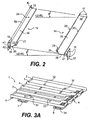
- Figure 2 illustrates a pair of racks 15, 14, removed from the cabinet 12.
- the left rack 15 is elevated relative to the right rack 14, so that a shelf assembly 1 supported on the pair of racks 15, 14 will be angled approximately eight degrees relative to horizontal.
- the right rack 14 includes a generally planar surface 35.
- the planar surface 35 is bordered by a left raised edge 23 and a right raised edge 20.
- a rear mounting bracket 36 is provided for connecting the right rack 14 to an interior rear wall of the cabinet 12.
- a front bracket 37 is provided for connecting the right rack 14 to the support column 13.
- a right hook 21 is located on the front mounting bracket 37 adjacent the support column 13.
- the left raised edge 23 stops short of a front edge 38 of the planar surface 35.
- From the end of the left raised edge 23 to the front edge 38 is an angled surface 25.
- the angled surface 25 is angled approximately forty five degrees relative to the left raised edge 23, and angled approximately forty five degrees relative to the front edge 38.
- a right projection 28 is located adjacent the intersection of the left raised edge 23 and the angled surface 25.
- the front mounting bracket 37 of the right rack 14 includes mounting holes 16. Appropriate mounting devices, such as screws or bolts, connect the front mounting bracket 37 to the support column 13.
- the rear mounting bracket 36 also includes mounting holes 17. Again, appropriate mounting devices, such as screws or bolts, connect the rear mounting bracket 36 to the interior rear wall of the cabinet 12.
- the interior rear wall may include two columns of mounting hooks which are horizontally spaced apart a distance equal to the spacing between the mounting holes 17 of the rear mounting bracket 17.
- the support column 13 may include a single column of mounting hooks which are vertically spaced apart a distance equal to the spacing between the mounting holes 16 of the front mounting bracket 37.
- the right rack 14 may be quickly and easily vertically adjusted inside the cabinet 12 of the vending machine. Vertical adjustment allows the vending machine to be set up, or modified, to vend items of various sizes. For example, several shelf assemblies 1 may be closely vertically spaced and vend twelve ounce cans, while a few other shelf assemblies 1 may have relatively greater vertical spacing and vend two liter, plastic containers.
- the left rack 15 is somewhat similar in structure to the right rack 14.
- the left rack 15 includes a generally planar surface 34.
- the planar surface 34 is bordered by a left raised edge 39 and a right raised edge 24.
- a rear mounting bracket 40 is provided for connecting the left rack 15 to a left interior sidewall of the cabinet 12.
- a front bracket 41 is provided for connecting the left rack 15 to the left interior sidewall.
- a left hook 22 is located in a middle section of a front edge 42 of the planar surface 34.
- the right raised edge 24 stops short of the front edge 42 of the planar surface 34.
- an angled surface 26 is angled approximately forty five degrees relative to the right raised edge 24, and angled approximately forty five degrees relative to the front edge 42.
- a left projection 27 is located adjacent the intersection of the right raised edge 24 and the angled surface 26.
- the rear mounting bracket 40 of the left rack 15 includes mounting holes 19, and the front mounting bracket 41 includes mounting holes 18.
- appropriate mounting devices such as screws or bolts, or a mounting hook arrangement, can be employed to adjustably connect the rear mounting bracket 40 and the front mounting bracket 41 to the left interior sidewall of the cabinet 12.
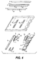
- FIGS 3A and 4 illustrates the shelf assembly 1.
- the main component of the shelf assembly 1 is a shelf pan 2.
- the shelf pan 2 could be made out of sheet metal, molded out of plastic, or formed using other suitable materials and methods.
- Dividers 3 are adjustably attached to a top surface of the shelf pan 2 by selectively aligning mounting holes 31 on side tabs of the dividers with adjustment holes 32 located in the shelf pan 2. Fixing devices, such as screws, rivets, bolt and nut arrangements, or mounting hooks are passed through the aligned holes to secure the dividers 3 to the shelf pan 2.
- the shelf assembly 1 can easily be modified to accommodate various sizes of beverage packages thereon.
- the shelf assembly 1 can accommodate containers laid on their sides, in rows two, three, or four deep on the shelf pan 2 depending on the heights of the containers.
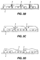
- Figure 3B illustrates the shelf assembly 1 with four rows of beverage containers C' having similar heights.
- the beverage containers C' are twelve ounce cans, and the dividers 3 are equally spaced apart.
- the first beverage container C' of each row is held and dispensed by a respective first gate 117 (as will be fully disclosed below in relation to Figures 21-34).
- the spacing between the dividers 3 can be modified, so that the shelf assembly 1 can accommodate three rows of taller, beverage containers C''.
- the forwardmost row is held and dispensed by the forwardmost first gate 117;
- the middle row is held and dispensed by the middle two first gates 117; and
- the rearmost row is held and dispensed by the rearmost first gate 117.
- the spacing between the dividers 3 can be modified, so that the shelf assembly 1 can accommodate two rows of even taller, beverage containers C'''.
- the forwardmost row is held and dispensed by the two forwardmost first gates 117; and the rearmost row is held and dispensed by the two rearmost first gates 117.
- the adjustable divider arrangement of the present invention allows for a multitude of various vending combinations.
- the vending machine can have certain shelf assemblies set up to exclusively dispense a given size of beverage container. For example, one shelf assembly dispenses only twelve ounce cans, another shelf assembly dispenses only one liter bottles, while another shelf assembly dispenses only 16 ounce cans, etc.
- each beverage container on a given shelf assembly 1 have substantially the same diameter. Therefore, no space inside the vending machine is wasted between adjacent shelf assemblies 1. Under this criteria, it would also be possible to vend beverage containers having different heights from the same shelf assembly, so long as their diameters were substantially equal. For example, one shelf assembly 1 could dispenses twelve ounce cans and sixteen ounce cans.
- the dividers 3 may be permanently attached to the shelf pan 2.
- the dividers 3 may be integrally formed with the shelf pan 2, welded thereto, or attached by other permanent or semi-permanent means.
- shelf assemblies 1 having varied divider layouts, would be available to vending machine service personnel. The service personnel would select the shelf assemblies 1 having divider layouts appropriate for the containers to be vended. The chosen shelf assemblies would be installed into the vending machine, rather than moving the dividers 3 of each shelf assembly in the vending machine.
- the escapement block assembly 4 includes a first handle 6 integrally formed at a front end, and a first pivot pin 5 formed at a back end.
- a guide slot 33 runs along an under surface of the escapement block assembly 4 from the front end to the back end.
- a second handle 7 and a slide bar 8 are attached to the underside of the shelf pan 2 .
- a back end of the slide bar 8 includes a second pivot pin 9.
- Two angle brackets 10 are attached to the underside of the shelf pan 2 via hinges 11.
- Each of the angle bracket 10 includes a first edge 29 and an angled edge 30.
- Each angle bracket 10 can be rotated about its hinge 11 so that the first edge 29 is perpendicular to the shelf pan 2.
- Figures 5 and 6 illustrate accessing the shelf assembly 1.
- the shelf assembly 1 would be accessed to load the shelf assembly, to clear jams, to inventory the vend articles, or to perform similar operations.
- a service person grasps the two handle 6 and 7 and pulls.
- Figure 5 illustrates the shelf assembly pulled out horizontally to its full extent. At this point, the service person would still be supporting the weight of the shelf assembly 1 via the handles 6 and 7.
- Figure 6 illustrates the shelf assembly 1 in a tilted position.
- the shelf assembly under the influence of gravity, naturally takes this position as the service person allows the shelf assembly to lower using the grips 6 and 7.
- the angle brackets 10 when the shelf assembly 1 is horizontally withdrawn from the cabinet 12 to its fullest extent, the angle brackets 10 no longer contact the left raised edge 23 of the right rack 14 or the right raised edge 24 of the left rack 15. Therefore, the angle brackets 10 are free, under the influence of gravity, to pivot about the hinges 11. Additionally, the angle brackets 10 may be spring biased to assist them in pivoting away from the undersurface of the shelf pan 2.
- each angle bracket 10 when the angle brackets 10 pivot, the first edge 29 of each angle bracket 10 will be angled approximately 90 degrees, with respect to the undersurface of the shelf pan 2.
- the first pivot pin 5 of the escapement block 4 is caught by the right hook 21 of the right rack 14.
- the second pivot pin 9 of the slide bar 8 is caught by the left hook 22.
- the first and second pivot pins 5, 9 engaging in the right and left hooks 21, 22, limit the horizontal sliding extent of the shelf assembly 1 relative to the cabinet 12, thus prevent the inadvertent complete withdrawal of the shelf assembly 1 from the cabinet 12. If it is desired to remove the shelf assembly 1 from the cabinet 12, the service person need only raise the rear end of the shelf assembly 1 so that the first and second pivot pins 5, 9 clear the right and left hooks 21, 22, while the shelf assembly 1 is being withdrawn from the cabinet 12.
- Figure 12 illustrates the shelf assembly 1 in a tilted state.
- the shelf may be easily withdrawn from the cabinet without the need for expensive or complicated hardware. For instance, no drawer slides, roller bearings, or other complex hardware are required. Such hardware would add the cost of additional equipment to the vending machine. Further, the hardware would require space accommodations on both sides of the shelf assembly.
- the elevator system 50 is mounted to the interior, right side wall of the cabinet 12.
- the primary function of the elevator system 50 is to receive a beverage container C item from a designated shelf assembly 1 and to deliver that beverage container C to the delivery mechanism 200.
- FIG. 13A shows the elevator system components.
- the elevator system 50 includes two interconnected drive pulleys 51 and 52.
- the drive pulleys 51 and 52 are interconnected by intermeshed gears 53.
- the drive pulleys 51 and 52 may be interconnected by belts, a direct frictional engagement, or any form of transmission.
- a motor drives at least one of the drive pulleys 51 and 52, or at least one of the gears 53, either directly or though a transmission system.
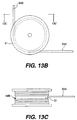
- FIGS 13B and 13C illustrate drive pulley 51, with its associated gear 53 removed to simplify the illustration.
- the drive pulley 51 is configured as a cylindrical drum with a flange formed on each end of the cylindrical drum.
- Drive cables 54A and 54B are wound about, and hence driven by, drive pulley 51.
- Drive pulley 52 is substantially identical in structure to drive pulley 51, and includes drive cables 55A and 55B wound thereabout, and hence driven thereby.
- drive cables 54A and 54B are wrapped around the drive pulley 51, such that drive cable 54A is wound-up upon paying-out of drive cable 54B, and visa versa.
- Drive cable 54A has one end attached to drive pulley 51, is wrapped about drive pulley 51 several times, then extends over a first idler pulley 68A and has its other end attached to an elevator back plate 56.
- Drive cable 54B has one end attached to drive pulley 51, is wrapped about drive pulley 51 several times, then extends through a cable tensioning mechanism 58 and has its other end attached to a counterweight 57.
- drive cables 55A and 55B are wrapped about the drive pulley 52, such that drive cable 55A is wound-up upon paying-out of drive cable 55B, and visa versa.
- Drive cable 55A has one end attached to drive pulley 52, is wrapped about drive pulley 52 several times, extends over a second idler pulley 68B, extends through the cable tensioning mechanism 58, and has its other end attached to the counterweight 57.
- Drive cable 55B has one end attached to drive pulley 52, is wrapped about drive pulley 52 several times, and has its other end attached to the elevator back plate 56.
- the cable tensioning mechanism 58 includes a plurality of tensioning pulleys through which the drive cables 54B and 55A pass. At least two of the tensioning pulleys are spring biased, so as to pull any slack out of the drive cables 54B and 55A. The at least two of the tensioning pulleys may be connected by a common spring (as is illustrated) or may be separately biased by individual springs, counterweights, or other forms of biasing devices.
- bearing cables 59 and 60 are also connected to the elevator back plate 56 and the counterweight 57.
- Bearing cable 59 has one end connected to the elevator back plate 56, passes over a third idler pulley 69A, and is then connected at its other end to the counterweight 57.
- Bearing cable 60 has one end connected to the counterweight 57, passes over a fourth idler pulley 69B, and is then connected at its other end to the elevator back plate 56.
- front and back guide bars 61 and 62 are attached to the interior, right side wall of the cabinet 12.
- the counterweight 57 includes protrusions 63 which are slidable inside internal slots 64 of the front and back guide bars 61 and 62.
- the elevator back plate 56 includes protrusions 67 which are slidable inside external slots 66 of the front and back guide bars 61 and 62. Since, the protruding dents 67 of the elevator back plate 56 include standoffs 65, the elevator is spaced slightly away from the guide bars 61 and 62. Therefore, the elevator back plate 56 and the counterweight 57 may pass one another while sliding in the guide bars 61 and 62.
- the elevator carry platform 70 is rigidly attached to the elevator back plate 56.
- the primary function of the elevator carry platform 70 is to support a beverage container C while it is being moved from a designated shelf assembly 1 to the delivery mechanism 200, and to dispense the beverage container C to the delivery port 100.
- the elevator platform 70 includes a flange portion 71 rigidly attached to the elevator back plate 56.
- the flange portion is encircled by a conveyor belt 73.
- the flange portion 71 includes a slanted portion 72 which is inclined relative to horizontal, such that a beverage container C located on the slanted portion 72 would tend to roll or slide toward the conveyor belt 73.
- the conveyor belt 73 is supported on the flanged portion 71 by suitable roller guides 74.
- a suitable drive mechanism causes selective movement of the conveyor belt 73.
- the drive pulleys 51 and 52 are caused to rotate and thereby move the drive cables 54A, 54B, 55A and 55B. Movement of the drive cables 54A, 54B, 55A and 55B causes the elevator carrying platform 70 to move vertically. The elevator carrying platform 70 is moved to a desired location adjacent a designated shelf assembly 1 under the control of a master controller.
- a beverage container C is dispensed from the escapement block 4 onto the slanted portion 72.
- the beverage container C slides or rolls onto the conveyor belt 73.
- the drive pulleys 51 and 52 are activated in order to drive the drive cables 54A, 54B, 55A and 55B to cause the elevator carrying platform 70 to move vertically into alignment with the delivery mechanism 200.
- the conveyor belt 73 then transports the beverage container C off a forward edge 75 of the conveyor belt 73 and into the delivery mechanism 200.
- the delivery mechanism 200 is attached to a back face of the vending machine's door.
- the primary function of the delivery mechanism 200 is to receive a beverage container C from the elevator carrying platform 70, and to gently move the beverage container C to a position adjacent the delivery port 100, so as to present the beverage container C to a customer in an upright orientation at a convenient height.
- the delivery mechanism 200 includes an outer housing 201.
- the outer housing 201 has an open top, open bottom, and an opening in a forwardly facing sidewall.
- the opening in the forwardly facing sidewall corresponds in size and position to an opening in the vending machine's door and constitutes the delivery port 100.
- a ramp 202 is formed along the upper edge of a rearwardly facing sidewall of outer housing 201.
- the ramp extends at an angle of approximately forty-five degrees to horizontal.
- the ramp 202 serves to guide a beverage container C into the open top of the outer housing 201 after the beverage container C has been delivered from the forward edge 75 of the conveyor belt 73.
- An L-shaped platform 203 is movably, attached to the outer housing 201 adjacent the open top of the outer housing 201.
- the L-shaped platform 203 is formed by the juncture of two legs, having an angle of approximately ninety degrees therebetween.
- a rearward edge of the L-shaped platform 203 includes a platform guide pin 204.
- the platform guide pin 204 includes two extension portions extending past opposite side edges of the L-shaped platform 203. The two extension portions are captured within channel guides 212 formed within opposite sides of the outer housing 201 so as to guide the movement of the rearward edge of the L-shaped platform 203.
- a forward edge of the L-shaped platform 203 includes a hinge 205.
- the hinge 205 is also attached to an upper edge of a delivery port door 206.
- the delivery port door 206 is pivotally attached to the L-shaped platform 203.
- a lower edge of the delivery port door 206 is connected to one end of a flexible cable 207.
- the flexible cable 207 passes over a guide pulley 208 and has its other end connected to a weight 209.
- the weight 209 is guided for vertical translation by a guide housing 210.
- the guide housing 210 is connected to a delivery port door opening mechanism 211, which will be explained in greater detail with reference to Figure 40.
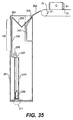
- the L-shaped platform 203 is initially located in an elevated position adjacent the open top of the outer housing 201. In the elevated position, the two legs of the L-shaped platform 203 are oriented at an angle of approximately forty-five degrees relative to horizontal, and the L-shaped platform 203 is ready to receive a beverage container C from the elevator carrying platform 70.
- the weight of the beverage container C causes the L-shaped platform 203 to descend.
- the descent of the rearward edge of L-shaped platform 203 is guided by the engagement between the extension portions of the platform pin 204 and the channel guides 212 formed in the outer housing 201.
- the descent of the forward edge of the L-shaped platform 203 is guided by the delivery port door 206, which includes side edges that run in tracks formed in the outer housing 201.
- Figure 38 illustrates the lowest position of descent of the L-shaped platform 203. At this position, one leg of the L-shaped platform 203 is horizontal, while the other leg is vertical. The delivery port door 206 has been completely lowered, thus providing access to the beverage container C, via the delivery port 100.
- Figure 39 illustrates the delivery mechanism once the beverage container C has been removed by the customer. Once the beverage container has been removed, the weight 209 causes the L-shaped platform 203 to ascend back to its elevated position of Figure 35.
- the speed of the descent and ascent of the L-shaped platform 203 is controlled by the speed of the vertical movement of the weight 209 within the guide housing 210.
- the speed of the vertical movement of the weight 209 is determined by the delivery port door opening mechanism 211.
- the delivery port door opening mechanism 211 controls the speed by regulating an air pressure between the weight 209 and the guide housing 210.
- the guide housing 210 has an air tight seal to a floor 213, which closes the open bottom of the outer housing 201.
- the cross-sectional configuration of the weight 209 is symmetrical to the cross-sectional configuration of the guide housing 210, but slightly smaller, thereby allowing air to slowly leak past the weight 209 and the walls of the guide housing 210. Therefore, the vertical movement of the weight 209 is retarded by an air vacuum formed beneath the weight when the weight is ascending, and a pressure formed beneath the weight 209 when the weight 209 is descending.
- the delivery port door opening mechanism 211 includes an air channel 212 communicating with a bottom of the guide housing 210.
- the air channel 212 branches into an air intake channel 214 and an air exhaust channel 215.
- the air intake channel 214 includes an intake check valve 216, which will only allow air to flow toward the air channel 212.
- An intake needle valve 217 is provided upstream of the intake check valve 216.
- the air exhaust channel 215 includes an exhaust check valve 218, which will only allow air to flow away from the air channel 212.
- An exhaust needle valve 219 is provided downstream of the exhaust check valve 218.
- Figure 15 illustrates four solenoid actuator mechanisms 80 attached to an undersurface of the elevator carrying platform 70. Each of the solenoid actuator mechanisms 80 is selectively capable of provoking the escapement block 4 to dispense a beverage container.
- Each solenoid actuator mechanism 80 includes an electromagnetic winding 81 which reciprocally controls a plunger 82.
- a bumper 83 is attached to an end of the plunger 82. The bumper 83 makes contact with a portion of the escapement block 4 to cause the escapement block 4 to dispense a beverage container C, as will be more fully described in conjunction with the description of the escapement block 4 to follow.
- Figure 16 illustrates the solenoid actuator mechanism 80 in an inactive state.
- the inactive state no power is supplied to the electromagnetic winding 81 of the solenoid actuator mechanism 80 by the master controller.
- the elevator carrying platform 70 is free to vertically move along the guide blocks 61 and 62 past the shelf assemblies 1 without causing any of the escapement blocks 4 to dispense beverage containers. No dispensing occurs because the bumper 83 is retracted toward the electromagnetic winding 81, and therefore does not physically contact any of the escapement blocks 4 of the shelf assemblies 1.
- Figure 17 illustrates the solenoid actuator mechanism 80 in an active state.
- power is supplied to the electromagnetic winding 81 of the solenoid actuator mechanism 80 by the master controller.
- the master controller determines that the elevator carrying platform 70 is adjacent the desired shelf assembly 1, the master controller supplies power to the electromagnetic winding 81 of one or more of the four solenoid actuator mechanisms 80.
- the plunger 82 of the selected solenoid actuator mechanism 80 extends to cause the bumper 83 to contact a portion of the escapement block 4.
- a beverage container located near the portion of the escapement block contacted, is dispensed onto the slanted portion 72 of the elevator carrying platform 70.
- more than one of the solenoid actuator mechanisms 80 may be simultaneously actuated. This simultaneous actuation could be used to simultaneously dispense two individual beverage containers from a single shelf assembly 1 onto the elevator carrying platform 70, or could be used to activate two portions of the escapement block 4, wherein both of the portions of the escapement block 4 must be activated before a large sized beverage container will be dispensed to the elevator carrying platform 70.
- the functions of the escapement block will be described in more detail later in the specification.
- Figures 18-20 illustrate a sensor arrangement for use by the master controller of the vending machine.
- the primary functions of the sensor arrangement are to determine the relative position of the elevator carrying platform 70, the shelf assemblies 1, and the cabinet 12, and to determine the stock status of beverage containers to be vended.
- the elevator carrying platform 70 includes a first sensor 91, a second sensor 92, and a third sensor 93.
- the first, second and third sensors 91, 92, and 93 are optical sensors, each including both a transmitter and a receiver of light rays.
- the sensors may be inductive coil type sensors or reed switches, physical parameter sensors, or other types of known sensors.
- the first sensor 91 of the elevator carrying platform 70 faces toward the interior, right side wall of the cabinet 12. Placed along the interior, right side wall are first indicators 90.
- the first indicators 90 are in the form of stickers or decals, or magnets if the first sensor 91 is a reed switch.
- Each decal is reflective and includes a code, such as a bar code, which can be easily read by the first sensor 91.
- a first decal is adhered near the topmost extent of the elevator shaft 16.
- a second decal is adhered near the lowermost extent of the elevator shaft 16, and a third decal is adhered to the sidewall adjacent the delivery mechansim 200.
- the second sensor 92 of the elevator carrying platform faces toward the shelf assemblies 1.
- Each shelf assembly 1 includes a second indicator 94.
- the second indicator 94 is attached to a portion of the escapement block 4, or the shelf assembly itself, which faces toward the elevator shaft 16.
- the second indicator 94 of each shelf assembly 1 is reflective and includes a code, such as a bar code.
- the second indicators 94 are magnets, if the second sensor 92 is a reed switch. The respective codes may be read by the second sensor 92, and used by the master controller to identify the shelf.
- the third sensor 93 of the elevator carrying platform 70 also faces toward the shelf assemblies 1.
- Each shelf assembly 1 includes a third indicator 95.
- the third indicator 95 is attached to a moveable member which is located below the shelf pan 2 and adjacent to the escapement block 4.
- the third indicator 95 also faces toward the elevator shaft 16, and has as its primary function to signal to the third sensor 95 whether a beverage container C normally found on the shelf assembly 1 is in-stock or out-of-stock.
- the third indicator 95 of each shelf assembly 1 is reflective, and may include a code.
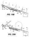
- Figure 19A shows the lower right end of a shelf assembly 1 with beverage containers C supported thereon, and held back by the first gate 117. The weight of at least one of the beverage containers C is rested upon a paddle 97.
- Paddle 97 is L-shaped and includes a first pivot point 98.
- a spring 99 tends to rotate the paddle 97 counterclockwise about the first pivot point 98, however the weight of the beverage container C is sufficient to overcome the biasing force of the spring 99. Therefore, a longer extent of the paddle 97, which contacts the beverage container C, tends to lye flat against the shelf pan 2 when a beverage container is located above the paddle 97.
- a shorter extend of the paddle 97 includes a second pivot 101 at its remote end.
- a linkage rod 102 is connected between the second pivot 101 and a back side of a swingable backboard 96.
- the swingable backboard 96 pivots about a third pivot point 103.
- the linkage rod 102 tends to swing the backboard 96 about the third pivot point 103 so that the backboard 96 is substantially perpendicular to the shelf pan 2.
- the third indicator 95 which is attached to the backboard 96, is detectable by the third sensor 93.
- the third indicator 95 of each shelf assembly 1 is a magnet
- the third sensor 93 is a reed switch.
- the components involved in this embodiment are less expensive, and hence this is the preferred embodiment.
- Figure 19B shows the lower right end of the shelf assembly 1 with beverage containers C supported thereon, and held back by the first gate 117. Again, the weight of at least one of the beverage containers C is rested upon the paddle 97.
- the actuating linkage assembly between the paddle 97 and the third indicator 95, i.e. the magnet, is different.
- the paddle 97 is L-shaped and includes a shorter extent having a pivot point 301 at one end.
- the pivot 301 is connected to a paddle frame 302. A longer extent of the L-shaped paddle 97 contacts beverage containers C on the shelf assembly 1.
- a linkage rod 303 is connected to a midportion of the longer extent of the L-shaped paddle 97 and to a sliding member 304.
- the connections between the linkage rod 303 and the L-shaped paddle 97 and sliding member 304 are hinged.
- the sliding member 304 is guided for transverse movement within the escapement block 4.
- a spring 305 engages the connection between the sliding member 304 and the linkage rod 303.
- the spring 305 applies a biasing force to this connection away from the elevator shaft 16. This biasing force tends to rotate the paddle 97 counterclockwise about the pivot 301, however the weight of the beverage container C is sufficient to overcome the biasing force of the spring 305. Therefore, the longer extent of the paddle 97, which contacts the beverage container C, tends to lye flat against the shelf pan 2, when a beverage container C is located above the paddle 97.
- the third indicator 95 While the longer extent of the paddle 97 is lying flat against the shelf pan 2, the third indicator 95 is located at a relatively close position to the elevator shaft 16. In this close position, the third sensor 93 can detect the third indicator 95, since the magnet of the third indicator 95 will radiate a field near the reed switch of the third sensor 93. The close position corresponds to an in-stock condition.
- the spring 305 causes the paddle 97 to rotate counterclockwise.
- the counterclockwise rotation of the paddle 97 causes the third indicator 95 to move to a position more remote from the elevator shaft 16.
- the third sensor 93 cannot detect the third indicator 95, since the radiated field of the magnet of the third indicator 95 will be distanced from the reed switch of the third sensor 93.
- the remote position corresponds to an out-of-stock condition.
- FIGS 19A and 19B illustrate that one or two beverage containers C can be held in escrow at the time that the out-of-stock indication is given.
- the out-of-stock indicator could be modified so that more or less beverage containers, or no beverage containers, are held in escrow, by simply moving the location of the paddle 97 relative to the shelf pan 2. Holding a beverage container in escrow is advantageous since upon reloading of the machine with ambient temperature beverage cans, at least the next-to-be-vended beverage container or containers will be in a chilled condition and therefore appropriate for immediate sale.
- out-of-stock indicator Although only one out-of-stock indicator has been illustrated on the escapement block 4 of each shelf assembly 1, it would be feasible that a plurality of out-of-stock indicators could be included on the escapement block 4 of each shelf assembly 1.
- the elevator carrying platform 70 would also include four third sensors 93. The four third sensors 93 would be spaced along the elevator carrying platform 70 to correspond to the locations of the four out-of-stock indicators of the escapement block 4 of the shelf assembly 1.
- the out-of-stock indication is given by the shelf assembly 1 using a purely mechanical device. Therefore, no electrical connection needs to be established between the vending machine and respective ones of the shelf assemblies to report the stock status of the respective shelf assemblies. This is particularly advantageous, since an electrical connection between a shelf assembly and the vending machine would be repeatedly stressed and worn during the sliding and tilting of the shelf assembly while the shelf assembly is being loaded or serviced.
- the vending machine Before a vending machine is used it must be set up or initialized. A service person will open the vending machine's cabinet 12, and inspect or adjust the vertical spacing between the shelf assemblies 1 and the horizontal spacing between the dividers 3 of each shelf assembly 1. The vertical spacings of the shelf assemblies 1 and the horizontal spacings between the dividers 3 of each shelf assembly 1 will be set to dimensions which are suitable for vending a combination of beverage containers which have been determined as suitable to the vending machine's location. For example, the vending machine may be set up to vend sixty percent twelve ounce cans, thirty percent sixteen ounce plastic containers, and ten percent one liter plastic containers.
- shelf assembly 1 After dimensional spacings for the shelf assemblies have been established, the service person slides out and tilts one of the shelf assemblies. Next, beverage containers to be vended are loaded between the dividers 3 of the titled shelf assembly 1. After the shelf assembly 1 has been loaded, it is lifted and horizontally slid back inside the cabinet 12 of the vending machine. The same procedure is repeated for the remaining shelf assemblies 1 of the vending machine.
- the service person uses an input device to program the master controller.
- the input device could be a customer's selection key pad, provided on the exterior of the vending machine, or it could be a separate dedicate keypad inside the vending machine.
- the service person programs information into the master controller such as the number of shelf assemblies 1 in the cabinet 12, the spacings between the shelf assemblies 1, the locations or ordering of the shelf assemblies 1 in the cabinet 12, the types of beverage containers to be vended, the prices of the beverage containers to be vended, and/or other similar data.
- an access door to the vending machine is closed and locked.
- the closing of the door is sensed by the master controller.
- the master controller signals the elevator drive system 50 to sweep the elevator carrying platform 70 from one end of the elevator shaft 16 to the other end.
- the second sensor 92 senses the second indicators 94 of each shelf assembly 1
- the sensed second indicators 94 are processed by the master controller in order to verify that the information programmed by the service person, concerning such parameters as the shelf assembly count and locations, is indeed correct.
- the service person need not program the master controller with details concerning the shelf assembly count and locations. Instead, the master controller can initially receive and store this data based upon the signals received from the second sensor 92 during the sweep of the elevator carrying platform 70.
- the elevator carrying platform 70 is elevated toward the top of the elevator shaft 16. Once the first sensor 91 senses the first decal, located near the topmost portion of the elevator shaft 16, the elevator drive system 50 causes the elevator carrying platform 70 to stop. The elevator carrying platform 70 stays parked at the topmost position of the elevator shaft 16, in a so-called "wait state" while the vending machine awaits a customer.
- the elevator shaft remains unencumbered, so that cool air may freely pass through the elevator shaft 16 to the beverage containers disposed on the shelf assemblies 1. This arrangement is particularly advantageous when the vending machine is to vend cold beverage containers. After each vend cycle, the elevator carrying platform 70 is again parked at the topmost portion of the elevator shaft 16, in order to maintain an unencumbered elevator shaft 16.
- the vending machine remains in the wait state, with the elevator carrying platform 70 parked, until a wake-up signal is generated by the master controller.
- the master controller generates the wake-up signal in response to a first coin, token, bill, card, or other form of payment, being received in the vending machine. Once a customer inserts the first coin, or other form of payment, the master controller's wake-up signal is transmitted to the elevator drive system 50.
- the elevator drive system 50 causes the elevator carrying platform 70 to move vertically downward until the first sensor 91 senses the third decal located adjacent the delivery port 100. Once the third decal is sensed the elevator is parked adjacent the third decal. The third decal is adjacent the delivery port 100 which is located midway along the elevator shaft 16. Therefore, the elevator carrying platform 70 will be parked midway along the elevator shaft 16, when positioned adjacent the third decal. By positioning the elevator carrying platform 70 midway, the vending time is reduced since the elevator carrying platform 70 will be optimally located to reduce its travel time to a random shelf assembly 1.
- the customer enters a selection of the beverage container which is desired.
- the master controller having been programmed, knows which shelf assemblies 1 contain the desired beverage container. Therefore, the master controller sends another signal to the elevator drive system 50 which causes the elevator carrying platform 70 to move to a shelf assembly 1 containing the desired beverage container.
- the second sensor 92 detects the second indicator 94 of each passing shelf assembly 1.
- the passing shelf assemblies 1 are counted, or otherwise analyzed, to verify and chart the location of the elevator carrying platform 70.
- the entertainment or information could be in the form of musical tones emitted from a speaker of the vending machine. Alternatively, a display of visual images on a screen of the vending machine could occur. Such entertainment or information reassures the customer that the vending machine has accepted the customer's selection and is in the process of vending the selected beverage container. Ultimately, the entertainment or information should continue until the selected beverage container is dispensed to the delivery port 100.
- the master controller causes the elevator carrying platform 70 to stop.
- the elevator carrying platform 70 is stopped at a position wherein the slanted portion 72 of the elevator carrying platform 70 is slightly above a dispensing location of the escapement block 4 of the desired shelf assembly 1.
- the master controller causes one or more of the solenoid actuator mechanisms 80 to move to the active state, as illustrated in Figure 17. Finally, the master controller causes the elevator carrying platform 70 to slowly move downward.
- the beverage container After the beverage container is dispensed onto the slanted portion 72 of the elevator carrying platform 70, the beverage container rolls or slides onto the conveyor 73.
- the elevator drive system 50 causes the elevator carrying platform 70, with the dispensed beverage container C, to move vertically until the first sensor 91 senses the third decal located adjacent the delivery mechanism 200.
- the master controller Upon sensing the third decal, the master controller causes the conveyor 73 to dispense the beverage container thereon to the delivery mechanism 200, such that the beverage container is dispensed to the delivery port 100, as discussed above.
- the master controller activates the elevator drive system 50 to cause the elevator carrying platform 70 to sweep the elevator shaft 16.
- the third sensor 93 senses the presence or absence of the third indicators 95 associated with each shelf assembly 1.
- the sensed presence of a third indicator 95 indicates that beverage containers associated with the out-of-stock mechanism are in-stock.
- the sensed absence of the third indicator 95 indicates that beverage containers associated with the out-of-stock mechanism are out-of-stock.
- the master controller receives the signals from the third sensor 93 and uses the received signals to analyze the entire status of the vending machine's stock. For example, simply because one shelf may be out of stock of its particular beverage container, does not mean that the entire vending machine is out of stock of that particular beverage container, since other shelf assemblies 1 may also contain the same particular beverage container. Once all the shelf assemblies containing a particular beverage container are out-of-stock, as indicated by the their respective third indicators, the master controller of the vending machine causes an out-of-stock indication to appear on the exterior of the vending machine to alert customers.
- the master controller may sweep the elevator carrying platform 70 after a predetermined number of vend cycles.
- the predetermined number of vending cycles is advantageously related to the number of beverage containers which remain in escrow after the out-of-stock indication is given by the out-of-stock mechanism.
- FIGs 3 and 4 illustrated the escapement block 4 in structural relation to the shelf pan 2.
- Each shelf assembly 1 includes an escapement block 4 which extends along the right side edge of the shelf assembly 1, closest to the elevator shaft 16.
- Each escapement block 4 contains four escapement mechanisms 109. Now, the specific details of the escapement mechanism 109 will be described with reference to Figures 21-34.
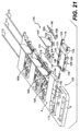
- FIG 21 shows the escapement block 4 with one of the escapement mechanisms 109 in an exploded view.
- Figure 22 shows an overhead view of the escapement mechanism 109.
- Each escapement mechanism 109 includes a slide 115 which reciprocally slides within a cutout portion 108 formed in the escapement block 4. The reciprocal sliding of the slide 115 is guided by a first guide pin 113 which engages in a first guide hole 107 of the slide 115.
- the slide 115 is normally biased away from the shelf assembly 1 toward the elevator shaft 16 by a guide spring 114.
- the slide 115 includes four sets of elongated slots.
- a first set of elongated slots 123 is formed near the rightmost edge of the slide 115.
- Second and third sets of elongated slots 124 and 125 are formed in the midsection of the slide 115.
- a fourth set of elongated slots 126 is formed near a leftmost edge of the slide 115.
- An actuation extension 116 is pivotally mounted within the slide 115.
- the actuation extension 116 includes two pivot guides 106.
- a second guide pin 110 passes through a first guide hole 119 formed in the escapement block 4, through the first set of elongated slots 123 of the slide 115, and through the two pivot guides 106 of the actuation extension 116.
- the second guide pin 110 is in the form of an elongated rod which extends approximately the entire length of the escapement block 4.
- a first gate 117 is also pivotally mounted within the slide 115.
- the first gate 117 includes two pivot guides 105.
- the second guide pin 110 also passes through the two pivot guides 105 of the first gate 117.
- a second gate 118 is also pivotally mounted within the slide 115.
- the second gate 118 includes two pivot guides 104.
- a third guide pin 111 passes through a second guide hole 120 formed in the escapement block 4, through the second set of elongated slots 124 of the slide 115, and through the two pivot guides 104 of the second gate 118.
- the third guide pin 111 is in the form of an elongated rod which extends approximately the entire length of the escapement block 4.
- a fourth guide pin 112 passes through a third guide hole 122 formed in the escapement block 4 and through the fourth set of elongated slots 126 of the slide 115.
- the fourth guide pin 112 is in the form of an elongated rod which extends approximately the entire length of the escapement block 4.
- a fourth guide hole 121 of the escapement block will be described later, in conjunction with the third set of slots 125 of the slide 115.
- Figures 23 and 24 are cross sectional views of the escapement mechanism 109 illustrating the slide 115 resting upon the cutout portion 108 of the escapement block 4.
- Figures 23 and 24 illustrate the slide 115 when it is slid to a rightmost position under the biasing force of the spring 114.
- the slide 115 includes a lower abutment 131 near the rightmost edge of the slide 115.
- the lower abutment 131 engages a lower portion 132 of the first gate 117.
- the contact between the lower abutment 131 and the lower portion of the first gate 117 causes the first gate 117 to assume a perpendicular relation to the slide 115.
- an inner portion of the lower abutment 131 engages an extension 133 of the actuation extension 116.
- the contact between the lower abutment 131 and the extension 133 of the actuation extension 116 causes the actuation extension 116 to assume an angular disposition relative to the slide 115.
- the actuation extension 116 extends at approximately a forty-five degree angle away from the slide 115, and extends beyond the rightmost edge of the slide 115.
- the slide 115 includes a first tab 129 and a second tab 130.
- the second gate 118 includes a first lever 134 and a second lever 135. A right edge of the first lever 134 is engaged against a left edge of the first tab 129.
- Figure 25 is identical to the cross sectional view of Figure 24, except for the presence of the beverage containers C and elevator carrying platform 70.
- Figures 26-28 are similar to the cross sectional views of Figures 24 and 25, but illustrate the escapement mechanism 109 in various progressive stages during the dispensing of a beverage container C onto the elevator carrying platform 70.
- Figure 29 is identical to the cross sectional view of Figure 23, except for the presence of the beverage containers C and elevator carrying platform 70.
- Figures 30-32 are similar to the cross sectional views of Figures 23 and 29, but illustrate the escapement mechanism 109 in various progressive stages during the dispensing of a beverage container C onto the elevator carrying platform 70.
- Figures 25 and 29 show the elevator carrying platform 70 located in a position which is slightly elevated relative to the shelf assembly 1.
- the actuator mechanism 80 has been placed in its active state by the master controller.
- the active state is characterized by the extended bumper 83.
- Figures 26 and 30 show the elevator carrying platform 70 after it has been slightly vertically lowered.
- the bumper 83 of the actuator mechanism 80 has contacted the actuation extension 116 of the escapement mechanism 109.
- the actuation extension 116 has pivoted about the second guide pin 110 until it now lies parallel to the slide 115.
- the pivoting motion has caused the extension 133 of actuation extension 116 to push the lower abutment 131 of the slide 115.
- Pushing the lower abutment 131 caused the slide 115 to slide leftward into the cutout portion 108 against the biasing force of the guide spring 114.
- the leftward motion of the slide 115 has also caused the portion of the lower abutment 131 for supporting the lower portion 132 of the first gate 117 to partially slide out from under the lower portion 132 of the first gate 117.
- Figure 26 Also of importance in Figure 26 is the interaction between the first lever 134 of the second gate 118 and the first tab 129 of slide 115. As the slide moves to the left, the left edge of first tab 129 presses against the right edge of the first lever 134. The pressure causes the second gate 118 to rise up from the slide 115. The second gate 118 acts to block a following beverage container C when elevated from the slide 115.
- Figures 27 and 31 illustrate the last instant of contact between the bumper 83 of the actuator mechanism 80 and the actuation extension 116. At this instant, the slide 115 is slid to its leftmost extent within the cutout portion 108 of the escapement block 4.
- the portion of the lower abutment 131 for supporting the lower portion 132 of the first gate 117 has completely slid out from under the lower portion 132 of the first gate 117. Since, the first gate 117 is not longer supported, the first gate 117 will fall clockwise under the influence of the weight of the beverage container C which rests thereagainst.
- Figures 28 and 32 illustrate the escapement mechanism 109 after elevator carrying platform 70 has past by, and the dispensing operation has finished.
- the first lever 134 reassumes a position of abutment against the left edge of the first tab 129. Also, as the slide 115 moves toward its rightmost position, the right edge of the first tab 129 pushes against the left edge of the second lever 135. The contact between the first tab 129 and the second lever 135 assures that the second gate 118 will again lie flat and parallel to the upper surface of the slide 115, such that beverage containers C may roll over the second gate 118 and come to rest against the first gate 117.
- the elevator carrying platform 70 need not be precisely located beside a shelf assembly before the actuator mechanism 80 is activated.
- the elevator carrying platform can be located anywhere within a tolerance zone above, or below, the shelf assembly prior to actuation of the actuator mechanism 80. This is because the escapement mechanism 109 dispenses in response to the passing of the bumper 83, rather than dispenses in response to a linear pressing by the bumper 83.
- the drive components of the elevator system need not be expensive and complex.
- the drive source would most likely be a stepper motor, however, the present invention performs using a simple DC motor.
- the drive cables 54A, 54B, 55A, and 55B and bearing cables 59, 60 would have to be immune to stretching, however, the present invention will tolerate low levels of stretch or give in the drive and bearing cables.
- Figures 33 and 34 illustrate an adjustable feature of the second gate 118.
- the second gate 118 can be pivotally attached to the slide 115 in one of two locations. The two locations allow the escapement mechanism 109 to dispense beverage containers C having a range of diameters (eg. 2 to 3.75 inches).
- Figure 33 illustrates the second gate 118 in a first location which is best suited for dispensing smaller beverage containers C.
- Figures 23-32 as described above, illustrated the connections and functioning of the second gate 118 when located in the first position.
- Figure 34 illustrates the second gate 118 in a second location which is best suited for dispensing larger diameter beverage containers C L .
- the third guide pin 111 is removed from the second guide hole 120 formed in the escapement block 4, and is inserted into the third guide hole 121 formed in the escapement block 4.
- the third guide pin 111 passes through the third guide hole 121, through the third set of elongated slots 125 of the slide 115, and through the two pivot guides 104 of the second gate 118.
- the second gate 118 operates in the same manner as described in relation to Figures 23-32 above, except that the first lever 134 is now manipulated by the second tab 130 of the slide 115, instead of the first tab 129. Therefore, the second gate 118 still serves to block the advance of stored beverage containers C L , while a single beverage can C L is dispensed onto the passing elevator carrying platform 70.
Landscapes
- Physics & Mathematics (AREA)
- General Physics & Mathematics (AREA)
- Vending Machines For Individual Products (AREA)
- Control Of Vending Devices And Auxiliary Devices For Vending Devices (AREA)
- Beverage Vending Machines With Cups, And Gas Or Electricity Vending Machines (AREA)
Applications Claiming Priority (2)
| Application Number | Priority Date | Filing Date | Title |
|---|---|---|---|
| US09/045,005 US6199720B1 (en) | 1998-03-20 | 1998-03-20 | Vending machine |
| EP99912599A EP1064627A2 (de) | 1998-03-20 | 1999-03-17 | Verkaufsautomat |
Related Parent Applications (1)
| Application Number | Title | Priority Date | Filing Date |
|---|---|---|---|
| EP99912599A Division EP1064627A2 (de) | 1998-03-20 | 1999-03-17 | Verkaufsautomat |
Publications (2)
| Publication Number | Publication Date |
|---|---|
| EP1684244A2 true EP1684244A2 (de) | 2006-07-26 |
| EP1684244A3 EP1684244A3 (de) | 2006-12-27 |
Family
ID=21935499
Family Applications (2)
| Application Number | Title | Priority Date | Filing Date |
|---|---|---|---|
| EP06009045A Withdrawn EP1684244A3 (de) | 1998-03-20 | 1999-03-17 | Verkaufsautomat |
| EP99912599A Withdrawn EP1064627A2 (de) | 1998-03-20 | 1999-03-17 | Verkaufsautomat |
Family Applications After (1)
| Application Number | Title | Priority Date | Filing Date |
|---|---|---|---|
| EP99912599A Withdrawn EP1064627A2 (de) | 1998-03-20 | 1999-03-17 | Verkaufsautomat |
Country Status (9)
| Country | Link |
|---|---|
| US (3) | US6199720B1 (de) |
| EP (2) | EP1684244A3 (de) |
| JP (1) | JP2002508553A (de) |
| CN (1) | CN1154076C (de) |
| AR (1) | AR014725A1 (de) |
| AU (1) | AU759156B2 (de) |
| BR (1) | BR9908973A (de) |
| WO (1) | WO1999049429A2 (de) |
| ZA (1) | ZA200004985B (de) |
Cited By (1)
| Publication number | Priority date | Publication date | Assignee | Title |
|---|---|---|---|---|
| EP1977981A1 (de) * | 2007-04-04 | 2008-10-08 | Rowa Automatisierungssysteme GmbH | Automatisiertes Stückgutlager mit geneigten Lagerschächten, die an ihrem unteren Ende eine von einem Bediengerät betätigbare Sperrvorrichtung aufweisen |
Families Citing this family (184)
| Publication number | Priority date | Publication date | Assignee | Title |
|---|---|---|---|---|
| US6181981B1 (en) | 1996-05-15 | 2001-01-30 | Marconi Communications Limited | Apparatus and method for improved vending machine inventory maintenance |
| US6199720B1 (en) * | 1998-03-20 | 2001-03-13 | The Coca-Cola Company | Vending machine |
| DE29817528U1 (de) * | 1998-10-01 | 2000-02-17 | Gebr. Willach GmbH, 53809 Ruppichteroth | Ausgabeautomat |
| US6286715B1 (en) * | 1999-04-01 | 2001-09-11 | The Coca-Cola Company | Transparent front vending machine |
| US6682289B1 (en) | 1999-04-02 | 2004-01-27 | The Coca-Cola Company | Dispensing apparatus and method of using same |
| CA2410049A1 (en) | 2000-05-23 | 2002-05-07 | Munroe Chirnomas | Method and apparatus for including article identification in an article handling device |
| EP1162582A3 (de) * | 2000-06-05 | 2003-03-12 | Sanden Corporation | Verkaufsautomat |
| US6892941B2 (en) | 2000-06-08 | 2005-05-17 | Mendota Healthcare, Inc. | Automatic prescription drug dispenser |
| US6371715B1 (en) * | 2000-07-03 | 2002-04-16 | Advanced Micro Devices, Inc. | Automated tube to tube transfer of a predetermined number of IC packages for various types of IC packages |
| US20020173885A1 (en) * | 2001-03-13 | 2002-11-21 | Lowrey Larkin Hill | Internet-based system for monitoring vehicles |
| US6957133B1 (en) | 2003-05-08 | 2005-10-18 | Reynolds & Reynolds Holdings, Inc. | Small-scale, integrated vehicle telematics device |
| US7904219B1 (en) | 2000-07-25 | 2011-03-08 | Htiip, Llc | Peripheral access devices and sensors for use with vehicle telematics devices and systems |
| US7228211B1 (en) | 2000-07-25 | 2007-06-05 | Hti Ip, Llc | Telematics device for vehicles with an interface for multiple peripheral devices |
| AU2001290661A1 (en) * | 2000-09-06 | 2002-03-22 | Advanced Pharmacy Technologies, L.L.C. | Automated prescription dispensing system and method of use |
| US7523159B1 (en) | 2001-03-14 | 2009-04-21 | Hti, Ip, Llc | Systems, methods and devices for a telematics web services interface feature |
| US6611740B2 (en) | 2001-03-14 | 2003-08-26 | Networkcar | Internet-based vehicle-diagnostic system |
| US6879894B1 (en) | 2001-04-30 | 2005-04-12 | Reynolds & Reynolds Holdings, Inc. | Internet-based emissions test for vehicles |
| US7702418B2 (en) * | 2001-06-13 | 2010-04-20 | Advanced Technology Materials, Inc. | Secure reader system |
| US6879876B2 (en) | 2001-06-13 | 2005-04-12 | Advanced Technology Materials, Inc. | Liquid handling system with electronic information storage |
| US6594579B1 (en) | 2001-08-06 | 2003-07-15 | Networkcar | Internet-based method for determining a vehicle's fuel efficiency |
| ITVR20010054U1 (it) * | 2001-10-05 | 2003-04-07 | Fas International Spa | Distributore automatico |
| JP3923295B2 (ja) * | 2001-10-22 | 2007-05-30 | サンデン株式会社 | 自動販売機 |
| US7174243B1 (en) | 2001-12-06 | 2007-02-06 | Hti Ip, Llc | Wireless, internet-based system for transmitting and analyzing GPS data |
| WO2003054812A2 (en) * | 2001-12-13 | 2003-07-03 | Cheol-Hun Choi | Vending machine |
| JP2003317143A (ja) * | 2002-04-24 | 2003-11-07 | Sanden Corp | 自動販売機の商品搬出装置 |
| ATE346352T1 (de) * | 2002-07-05 | 2006-12-15 | Gross & Edgerton Ltd | Vorrichtung und verfahren zum verkaufen von produkten in verschiedenen grössen |
| US7032776B2 (en) * | 2002-08-08 | 2006-04-25 | The Vendo Company | Vending machine bucket drive control |
| US20040073334A1 (en) * | 2002-10-09 | 2004-04-15 | Terranova Steven N. | Communication system for vended goods |
| ITPN20020055U1 (it) * | 2002-11-21 | 2004-05-22 | Necta Vending Solutions Spa | Distributore automatico di prodotti confezionati |
| US20030146233A1 (en) * | 2002-11-23 | 2003-08-07 | Munroe Chirnomas | Method and apparatus for including article identification in an article handling device |
| JP3684227B2 (ja) * | 2002-12-02 | 2005-08-17 | 照明 伊藤 | 分注チップ自動供給装置 |
| US7123989B2 (en) * | 2003-07-01 | 2006-10-17 | Asteres, Inc. | System and method for providing a random access and random load dispensing unit |
| CA2533754C (en) * | 2003-06-30 | 2013-10-22 | Asteres Inc. | Random access and random load dispensing unit |
| US20050192705A1 (en) | 2003-07-01 | 2005-09-01 | Asteres Inc. | Random access and random load dispensing unit |
| US9520005B2 (en) | 2003-07-24 | 2016-12-13 | Verizon Telematics Inc. | Wireless vehicle-monitoring system |
| US7113127B1 (en) * | 2003-07-24 | 2006-09-26 | Reynolds And Reynolds Holdings, Inc. | Wireless vehicle-monitoring system operating on both terrestrial and satellite networks |
| US7222748B2 (en) * | 2003-09-26 | 2007-05-29 | Royal Vendors, Inc. | Clear door vending machine |
| US8215520B2 (en) | 2003-10-17 | 2012-07-10 | Rock-Tenn Shared Services, Llc | Secure merchandising system |
| US20060237381A1 (en) * | 2005-04-25 | 2006-10-26 | Lockwood Thomas A | Time delay product pushing system |
| US8485391B2 (en) * | 2003-10-17 | 2013-07-16 | Rock-Tenn Shared Services, Llc | Theft deterrent system |
| US8190289B2 (en) | 2003-10-17 | 2012-05-29 | Rock-Tenn Shared Services, Llc | Dispensing and display system |
| US7641072B1 (en) | 2003-10-17 | 2010-01-05 | Rock-Tenn Shared Services, Llc | Theft deterrent system |
| US8015727B2 (en) * | 2003-11-11 | 2011-09-13 | Lg Electronics Inc. | Dryer rack |
| EP1763851A4 (de) * | 2004-02-27 | 2011-11-30 | Sandenvendo America Inc | Verkaufsautomat und bestandteile |
| US7837059B2 (en) * | 2004-02-27 | 2010-11-23 | Sanden Vendo America, Inc. | Product acquisition devices and methods for vending machines |
| US8162174B2 (en) * | 2004-02-27 | 2012-04-24 | Sandenvendo America, Inc. | Retrieval systems for vending machines |
| EP1730708B1 (de) * | 2004-03-01 | 2009-07-29 | STAAKE Investment & Consulting GmbH & Co. KG | Automatischer spender für voluminöse und/oder schwere produkte und/oder produkte in paketen |
| US20070138199A1 (en) * | 2004-03-09 | 2007-06-21 | Jae-Jeong Yang | Feed mechanism for a vending machine |
| US7447605B2 (en) * | 2004-04-15 | 2008-11-04 | Redbox Automated Retail, Llc | System and method for calibrating a vending apparatus |
| US7584869B2 (en) * | 2004-04-15 | 2009-09-08 | Redbox Automated Retail, Llc | Article dispensing system and method for same |
| US7225065B1 (en) | 2004-04-26 | 2007-05-29 | Hti Ip, Llc | In-vehicle wiring harness with multiple adaptors for an on-board diagnostic connector |
| JP4551396B2 (ja) * | 2004-05-19 | 2010-09-29 | 株式会社湯山製作所 | 薬品払出装置 |
| CN1976671B (zh) * | 2004-05-19 | 2011-02-09 | 株式会社汤山制作所 | 药品分配装置 |
| ES2257933B1 (es) * | 2004-08-25 | 2007-07-01 | Desarrollo Y Servicios De Vending De Navarra, S.L. | Maquina de autodispensacion modular. |
| US20060108757A1 (en) * | 2004-09-24 | 2006-05-25 | Brookmire Derek A | Catering cart having gravity-feed and counter system |
| JP4601386B2 (ja) * | 2004-10-15 | 2010-12-22 | 株式会社湯山製作所 | 薬剤カート |
| CA2597400C (en) * | 2005-02-09 | 2015-08-11 | Bld Oriental, Ltd. | Automatic vending machine |
| DE102005006473A1 (de) * | 2005-02-12 | 2006-08-17 | Deutsche Wurlitzer Gmbh | Ablaufsteuerung für Warenautomat |
| JP2006244207A (ja) * | 2005-03-04 | 2006-09-14 | Sanden Corp | 自動販売機 |
| WO2006116110A2 (en) * | 2005-04-22 | 2006-11-02 | Redbox Automated Retail, L.L.C. | System and method for communicating vending information |
| US8060247B2 (en) * | 2005-04-22 | 2011-11-15 | Redbox Automated Retail, Llc | System and method for communicating secondary vending options |
| US8353425B2 (en) * | 2005-04-25 | 2013-01-15 | Rock-Tenn Shared Services, Llc | Time delay product pushing system |
| US20060266762A1 (en) * | 2005-05-02 | 2006-11-30 | Richard Andrews | Theft deterrent system |
| US7686185B2 (en) | 2005-06-02 | 2010-03-30 | Coin Acceptors, Inc. | Dispenser tray for a vending machine |
| US20070017928A1 (en) * | 2005-07-20 | 2007-01-25 | Coppola Richard G | Method of retrofitting a vending machine |
| US20070026916A1 (en) * | 2005-07-28 | 2007-02-01 | Idx, Inc. | Vending machine having a game of chance |
| ES2277532B2 (es) * | 2005-08-25 | 2008-03-01 | Jofemar, S.A. | Dispositivo publicitario para maquinas expendedoras. |
| US20070151981A1 (en) * | 2005-09-27 | 2007-07-05 | Leonard Halsey | Firewood dispenser |
| US7604145B2 (en) * | 2005-10-14 | 2009-10-20 | Dixie-Narco, Inc. | Drive system for a vending machine dispensing assembly |
| US7802700B2 (en) * | 2005-10-14 | 2010-09-28 | Crane Merchandising Systems, Inc. | Product discharge and delivery system for a vending machine |
| US7837058B2 (en) * | 2005-10-14 | 2010-11-23 | Crane Merchandising Systems, Inc. | Product transport system for a vending machine |
| US7571833B2 (en) * | 2005-11-30 | 2009-08-11 | Fki Security Products | Bulk coin dispenser |
| US7533784B2 (en) | 2006-06-12 | 2009-05-19 | Rock-Tenn Shared Services, Llc | Theft deterrent system hook |
| CN103778700A (zh) | 2006-07-10 | 2014-05-07 | 高级技术材料公司 | 材料管理系统及材料管理方法 |
| US20080067187A1 (en) * | 2006-09-01 | 2008-03-20 | The Coca-Cola Company | Under the Counter Beverage Cooler |
| US8534494B2 (en) * | 2006-10-26 | 2013-09-17 | Crane Merchandising Systems, Inc. | Product detection system for a vending machine |
| US20080142537A1 (en) * | 2006-12-14 | 2008-06-19 | The Coca-Cola Company | First in First Out Vending Systems |
| US7783379B2 (en) * | 2007-04-25 | 2010-08-24 | Asteres, Inc. | Automated vending of products containing controlled substances |
| JP5013978B2 (ja) * | 2007-06-11 | 2012-08-29 | サンデン株式会社 | 自動販売機 |
| US20090078718A1 (en) * | 2007-09-25 | 2009-03-26 | The Coca-Cola Company | System and Method for Reading Inventory in a Vending Machine |
| US20090089187A1 (en) * | 2007-09-28 | 2009-04-02 | Redbox Automated Retail, Llc | Article Vending Machine And Method for Auditing Inventory While Article Vending Machine Remains Operational |
| US9886809B2 (en) | 2007-09-28 | 2018-02-06 | Redbox Automated Retail, Llc | Article dispensing machine and method for auditing inventory while article dispensing machine remains operational |
| US8712872B2 (en) | 2012-03-07 | 2014-04-29 | Redbox Automated Retail, Llc | System and method for optimizing utilization of inventory space for dispensable articles |
| US8768789B2 (en) | 2012-03-07 | 2014-07-01 | Redbox Automated Retail, Llc | System and method for optimizing utilization of inventory space for dispensable articles |
| EP2043061A1 (de) * | 2007-09-28 | 2009-04-01 | Innospense Capital B.V. | Abgabevorrichtung und Verfahren zur Abgabe einzelner Waren, insbesondere Medikamentenverpackungen |
| US20090090735A1 (en) * | 2007-10-03 | 2009-04-09 | Dan Cooper | Novel Modular Vending Machine for Packaged Goods |
| ITTO20080360A1 (it) * | 2008-05-14 | 2009-11-15 | N&W Global Vending Spa | Distributore automatico di prodotti |
| ITTO20080367A1 (it) * | 2008-05-15 | 2009-11-16 | N&W Global Vending Spa | Metodo e distributore automatico per l'erogazione di prodotti |
| US9280863B2 (en) * | 2008-07-16 | 2016-03-08 | Parata Systems, Llc | Automated dispensing system for pharmaceuticals and other medical items |
| US20100140286A1 (en) * | 2008-12-08 | 2010-06-10 | Michael Christopher Quinn | Portable beverage machine |
| ES2352285B1 (es) * | 2009-01-29 | 2011-12-26 | Investronica, S.A. | Máquina para la venta automática de productos. |
| ITTO20090241A1 (it) * | 2009-03-30 | 2010-09-30 | N&W Global Vending Spa | Distributore automatico di prodotti |
| US20110024202A1 (en) * | 2009-07-31 | 2011-02-03 | Shian-Tsong Chen | Height and weight scale |
| US20110047010A1 (en) * | 2009-08-21 | 2011-02-24 | Redbox Automated Retail, Llc | Article vending machine and method for receiving restricted discount codes |
| US8678232B2 (en) * | 2009-08-27 | 2014-03-25 | Utique, Inc. | Inventory storage and dispensing mechanism |
| US9104990B2 (en) | 2009-09-05 | 2015-08-11 | Redbox Automated Retail, Llc | Article vending machine and method for exchanging an inoperable article for an operable article |
| US8996162B2 (en) * | 2009-09-05 | 2015-03-31 | Redbox Automated Retail, Llc | Article vending machine and method for exchanging an inoperable article for an operable article |
| DE102009041238A1 (de) * | 2009-09-11 | 2011-03-24 | Krones Ag | Vorrichtung und Verfahren zum Beladen eines Gebindespeichers |
| US9119488B2 (en) | 2009-09-25 | 2015-09-01 | Rock-Tenn Shared Services, Llc | Secure merchandising display with blocker mechanisms |
| US8448815B2 (en) * | 2009-11-23 | 2013-05-28 | Meadwestvaco Corporation | Product dispenser with low product indicator |
| US7922437B1 (en) * | 2009-11-23 | 2011-04-12 | Meadwestvaco Corporation | Display system, dispensing device and package for use therein |
| US20110121011A1 (en) * | 2009-11-23 | 2011-05-26 | John Gelardi | Product Dispensing System With Anti-Theft Engagement |
| US9633503B2 (en) * | 2010-03-16 | 2017-04-25 | The Coca-Cola Company | Vendor |
| US10600273B2 (en) | 2010-03-16 | 2020-03-24 | The Coca-Cola Company | Vendor |
| US8646650B2 (en) | 2010-05-19 | 2014-02-11 | Rock-Tenn Shared Services, Llc | Product dispensing system |
| US8322543B2 (en) | 2010-07-23 | 2012-12-04 | Meadwestvaco Corporation | Product dispensing apparatus and system |
| US8538581B2 (en) | 2010-09-03 | 2013-09-17 | Redbox Automated Retail, Llc | Article vending machine and method for authenticating received articles |
| US9569911B2 (en) | 2010-08-23 | 2017-02-14 | Redbox Automated Retail, Llc | Secondary media return system and method |
| US8628003B2 (en) | 2010-09-25 | 2014-01-14 | Meadwestvaco Corporation | Product dispensing container, system and method with priming area |
| US9090390B2 (en) | 2010-09-27 | 2015-07-28 | Meadwestvaco Corporation | Product dispensing system |
| US20120097694A1 (en) * | 2010-10-21 | 2012-04-26 | Gelardi John A | Product Dispensing and Orienting System |
| CN102486879A (zh) * | 2010-12-02 | 2012-06-06 | 永晋能源科技有限公司 | 多功能智能型自动售货机 |
| US9640014B2 (en) * | 2011-01-04 | 2017-05-02 | Fawn Engineering Corporation | Vending machine with elevator delivery of vended product to customer access |
| US8308023B2 (en) | 2011-02-23 | 2012-11-13 | Meadwestvaco Corporation | Product dispensing system with directional flexing container |
| US9174785B2 (en) | 2011-02-23 | 2015-11-03 | Westrock Mwv, Llc | Product dispensing system with panel guide |
| JP5949011B2 (ja) * | 2011-04-21 | 2016-07-06 | 富士電機株式会社 | 自動販売機の商品搬出装置 |
| US8668114B2 (en) | 2011-05-02 | 2014-03-11 | Meadwestvaco Corporation | Dispensing system and package for use therewith |
| US8910827B2 (en) | 2011-05-10 | 2014-12-16 | Rock-Tenn Shared Services, Llc | Secure merchandising display with tunnel feature |
| US8302809B1 (en) | 2011-05-11 | 2012-11-06 | Meadwestvaco Corporation | Product dispensing system with increased product-to-dispenser contact |
| CN103958270B (zh) * | 2011-05-25 | 2016-05-04 | 施拉奇锁有限责任公司 | 用于运输装置的锁安装组件 |
| CA2838944A1 (en) | 2011-06-14 | 2012-12-20 | Redbox Automated Retail, Llc | System and method for substituting a media article with alternative media |
| US9359106B2 (en) | 2011-07-18 | 2016-06-07 | Westrock Mwv, Llc | Product dispensing system with multiple dispensing decks |
| CA2842293C (en) | 2011-07-20 | 2019-10-22 | Redbox Automated Retail, Llc | System and method for providing the identification of geographically closest article dispensing machines |
| CA2843589A1 (en) | 2011-08-02 | 2013-02-07 | Redbox Automated Retail, Llc | System and method for generating notifications related to new media |
| US9286617B2 (en) | 2011-08-12 | 2016-03-15 | Redbox Automated Retail, Llc | System and method for applying parental control limits from content providers to media content |
| US8985346B2 (en) | 2011-09-08 | 2015-03-24 | Meadwestvaco Corporation | Multi-deck product dispensing system with rear guide |
| US8550261B2 (en) | 2011-09-09 | 2013-10-08 | Meadwestvaco Corporation | Product dispensing system with flexing container |
| US8833601B2 (en) | 2012-02-24 | 2014-09-16 | Meadwestvaco Corporation | Product dispensing system with staggered perforations |
| DE102012006832A1 (de) * | 2012-04-03 | 2013-10-10 | Faurecia Innenraum Systeme Gmbh | Auszug für eine schublade, schublade mit einem auszug und fahrzeug mit einer schublade |
| US8851302B2 (en) | 2012-04-16 | 2014-10-07 | Meadwestvaco Corporation | Product dispensing system with container-product interaction |
| US9747253B2 (en) | 2012-06-05 | 2017-08-29 | Redbox Automated Retail, Llc | System and method for simultaneous article retrieval and transaction validation |
| US9536236B2 (en) | 2012-06-08 | 2017-01-03 | Ronny Hay | Computer-controlled, unattended, automated checkout store outlet and related method |
| US10083430B2 (en) | 2012-06-08 | 2018-09-25 | Ronny Hay | Computer-controlled, unattended, automated checkout store outlet system and related method |
| US8657126B1 (en) | 2012-08-27 | 2014-02-25 | Meadwestvaco Corporation | Product dispensing system with dispenser door |
| US9320365B2 (en) | 2012-08-31 | 2016-04-26 | Westrock Mwv, Llc | Product dispensing system with sound reducing features |
| US20140089077A1 (en) * | 2012-09-21 | 2014-03-27 | Coinstar, Inc. | Consumer operated kiosks for purchasing fresh foods and associated systems and methods |
| KR101416024B1 (ko) * | 2012-12-04 | 2014-07-08 | 롯데알미늄 주식회사 | 멀티 자동판매기의 가격설정장치 및 그 방법 |
| KR101416022B1 (ko) * | 2012-12-04 | 2014-07-08 | 롯데알미늄 주식회사 | 멀티자동판매기의 선반제어정보 관리장치 |
| CN103886680A (zh) * | 2012-12-21 | 2014-06-25 | 鸿富锦精密工业(武汉)有限公司 | 自动售货机 |
| CN103886682B (zh) * | 2012-12-22 | 2016-12-21 | 重庆界威模具股份有限公司 | 自动售货机 |
| CN103903342A (zh) * | 2012-12-27 | 2014-07-02 | 鸿富锦精密工业(武汉)有限公司 | 自动售货机 |
| CN103903349A (zh) * | 2012-12-29 | 2014-07-02 | 鸿富锦精密工业(武汉)有限公司 | 自动售货机的货盘 |
| US9096345B2 (en) | 2013-08-22 | 2015-08-04 | Meadwestvaco Corporation | Product dispensing system with reinforced weakening features |
| US9870671B1 (en) | 2014-04-07 | 2018-01-16 | Fawn Engineering Corporation | Mechanical lift for delivery bins in vending machines |
| CN105303697A (zh) * | 2014-07-08 | 2016-02-03 | 广州星韧兴尘广告有限公司 | 一种全自动礼品派发机 |
| CN105692186B (zh) * | 2014-11-27 | 2019-02-12 | 海信容声(广东)冰箱有限公司 | 一种饮料机送料机构及送料方法、饮料机 |
| CN108280943A (zh) * | 2015-06-09 | 2018-07-13 | 吴小再 | 一种快递柜及其工作法 |
| US20170088410A1 (en) | 2015-09-30 | 2017-03-30 | Hydration Labs, Inc. | Beverage dispensing |
| JP6711507B2 (ja) * | 2015-10-16 | 2020-06-17 | サンデン・リテールシステム株式会社 | 自動販売機の商品搬出装置 |
| US9987747B2 (en) * | 2016-05-24 | 2018-06-05 | Semes Co., Ltd. | Stocker for receiving cassettes and method of teaching a stocker robot disposed therein |
| US10332331B2 (en) | 2016-10-14 | 2019-06-25 | Pepsico, Inc. | Modular vending machine |
| US10490014B2 (en) | 2016-12-16 | 2019-11-26 | Pepsico, Inc. | Lean vending machine |
| EP3568841B1 (de) * | 2017-01-12 | 2024-10-09 | Crane Payment Innovations, Inc. | Verbessertes produktabgabesystem für verkaufsautomat |
| CN107242790A (zh) * | 2017-05-05 | 2017-10-13 | 南安市申达鑫通商贸有限公司 | 一种多阀饮料机 |
| CN107316385A (zh) * | 2017-06-20 | 2017-11-03 | 广州市创赢电子产品有限公司 | 一种具有售货和制作饮料功能的自动贩售机 |
| CN107610355A (zh) * | 2017-08-29 | 2018-01-19 | 深圳志合天成科技有限公司 | 一种自助终端机的控制方法 |
| BE1025544B1 (nl) * | 2017-09-01 | 2019-04-08 | Anheuser-Busch Inbev Nv | Oriëntatiesysteem voor drankblikken |
| BE1024967B1 (nl) * | 2017-09-01 | 2018-08-29 | Anheuser-Busch Inbev Nv | Automatisch verkoopautomaat voor drankblikken |
| BE1025543B1 (nl) | 2017-09-01 | 2019-04-08 | Anheuser-Busch Inbev Nv | Openingshulpmiddel voor drankblikken |
| CN109523701A (zh) * | 2017-09-18 | 2019-03-26 | 鸿富锦精密工业(武汉)有限公司 | 自动售货机 |
| MX2020004161A (es) * | 2017-10-10 | 2021-01-08 | Tranzonic Companies | Aparato y metodo para surtir productos de higiene femenina usando un sensor de movimiento. |
| CN108053555B (zh) * | 2017-12-27 | 2018-12-14 | 李平 | 一种饮料自动售货机专用供货装置 |
| US11839534B2 (en) * | 2018-01-03 | 2023-12-12 | Tranzonic Companies | Apparatus and method to dispense sanitary hygiene products |
| US11148927B2 (en) | 2018-07-27 | 2021-10-19 | Hydration Labs, Inc. | Beverage dispensing |
| CN109658596A (zh) * | 2018-09-12 | 2019-04-19 | 盈奇科技(深圳)有限公司 | 一种重力感应自动售货机 |
| US11378968B2 (en) * | 2018-10-22 | 2022-07-05 | Walmart Apollo, Llc | Autonomous ground vehicle (AGV) cart for item distribution |
| CN111292477A (zh) * | 2018-12-10 | 2020-06-16 | 周口师范学院 | 一种配合无人机使用的快递柜 |
| US11449826B2 (en) * | 2019-03-15 | 2022-09-20 | Hashim Muhammad SIDDIQUI | Systems and methods for autonomous inventory counting and tracking |
| US11504602B2 (en) | 2019-04-08 | 2022-11-22 | Barzcash Inc. | System, method, and apparatus for tracking machine use |
| US11348405B2 (en) | 2019-04-08 | 2022-05-31 | Barzcash Inc. | System, method, and apparatus for tracking machine use |
| US10781609B2 (en) | 2019-07-12 | 2020-09-22 | Alibaba Group Holding Limited | Electronic door opening/closing apparatus and electronic door opening/closing detection method, apparatus and device |
| USD924330S1 (en) | 2019-11-26 | 2021-07-06 | Applestone Meat Company Llc | Item carrier |
| USD924329S1 (en) | 2019-11-26 | 2021-07-06 | Applestone Meat Company Llc | Outer shell of an item carrier |
| USD924328S1 (en) | 2019-11-26 | 2021-07-06 | Applestone Meat Company Llc | Inner shell of an item carrier |
| USD920020S1 (en) | 2019-11-26 | 2021-05-25 | Applestone Meat Company Llc | Carousel |
| WO2021222627A1 (en) | 2020-04-30 | 2021-11-04 | Crane Merchandising Systems, Inc. | Vending machine product delivery system with variable retrieval speed |
| CN111623591B (zh) * | 2020-06-08 | 2025-01-21 | 浙江云之羽科技发展有限公司 | 搁架结构及其冷柜 |
| USD998401S1 (en) | 2020-08-31 | 2023-09-12 | Hydration Labs, Inc. | Dispensing device |
| WO2022109300A1 (en) * | 2020-11-23 | 2022-05-27 | Barzcash Inc. | System, method, and apparatus for tracking machine use |
| CN112489300B (zh) * | 2020-12-16 | 2024-12-13 | 苏州雪电通讯科技股份有限公司 | 自动售货机 |
| EP4278335A4 (de) * | 2021-01-18 | 2024-05-08 | Cintas Corporate Services, Inc. | Automatisierter spender für kleidungsstücke und andere artikel und zugehörige verfahren |
| CA3206698A1 (en) * | 2021-02-02 | 2022-08-11 | Pepsico, Inc. | Product release mechanisms and vending machines having product release mechanisms |
| US20220315352A1 (en) * | 2021-03-31 | 2022-10-06 | Dexterity, Inc. | Kitting shelf machine with self-loading presentation face |
| CN113697275B (zh) * | 2021-08-12 | 2024-07-05 | 北京远鲸科技有限公司 | 货柜及其储物箱调度方法、组合货柜 |
Family Cites Families (58)
| Publication number | Priority date | Publication date | Assignee | Title |
|---|---|---|---|---|
| GB438916A (en) | 1934-11-14 | 1935-11-26 | Bournemouth Ice & Ice Cream Fa | Improvements in or relating to vending machines |
| US2440251A (en) | 1944-06-21 | 1948-04-27 | Joseph M Devens | Vending machine |
| US2615773A (en) | 1948-06-26 | 1952-10-28 | Marcus L Holt | Vending machine for cylindrical articles |
| US2770393A (en) | 1952-02-01 | 1956-11-13 | Universal Vendor Company | Dispensing or vending machine |
| US3294282A (en) * | 1963-09-09 | 1966-12-27 | Kenneth G Brown | Package dispensing means with delivery elevator |
| US3348732A (en) | 1966-09-02 | 1967-10-24 | Schwarz Heinz Walter | Article dispensing device |
| US3752357A (en) * | 1970-12-23 | 1973-08-14 | Rowe International Inc | High capacity, small size vendor for cans |
| US3722744A (en) | 1972-03-08 | 1973-03-27 | Cavalier Corp | Split vend gate mechanism |
| US3802881A (en) * | 1972-04-24 | 1974-04-09 | Polaroid Corp | Color diffusion transfer film with whitening agent |
| US3810560A (en) | 1973-05-21 | 1974-05-14 | B Stegeman | Dispenser with adjustable paddle vending member |
| US3990754A (en) | 1974-03-25 | 1976-11-09 | Rowe International Inc. | Merchandising machine cabinet and shelf structure |
| CA1039245A (en) | 1975-05-14 | 1978-09-26 | Leonard P. Falk | Article vendor with elevator |
| SU600040A1 (ru) * | 1975-11-19 | 1978-03-30 | Издательство "Известия" | Склад дл хранени и выдачи изделий цилиндрической формы |
| US4252250A (en) | 1978-09-28 | 1981-02-24 | Umc Industries, Inc. | Multiple-beam optical sensing system for an article vendor |
| US4303179A (en) | 1980-01-04 | 1981-12-01 | La Crosse Cooler Company | High density can stack for automatic can venders |
| US4319742A (en) | 1980-06-23 | 1982-03-16 | Minnesota Mining And Manufacturing Company | Sheet supply detector and indicator |
| US4483459A (en) | 1981-07-24 | 1984-11-20 | Mars Limited | Dispensing machine |
| SU1007917A1 (ru) * | 1981-12-31 | 1983-03-30 | Научно-исследовательский конструкторско-технологический институт тракторных и комбайновых двигателей | Устройство дл выдачи деталей |
| US4511059A (en) | 1983-05-26 | 1985-04-16 | Cavalier Corporation | Vending machine with side mounted escrows |
| US4560088A (en) * | 1984-05-11 | 1985-12-24 | Tan Larry K | Vending machine with dispensing operating system movable in X-Y coordinate axes |
| US4706794A (en) | 1984-09-20 | 1987-11-17 | Sanyo Electric Co., Ltd. | Vending machine with a common display |
| US4967896A (en) | 1985-03-04 | 1990-11-06 | Tokyo Sanyo Electric Co., Ltd. | Control arrangement for automatic vending machine |
| US4812629A (en) | 1985-03-06 | 1989-03-14 | Term-Tronics, Incorporated | Method and apparatus for vending |
| JPH0237080Y2 (de) * | 1985-09-12 | 1990-10-08 | ||
| JPH0441416Y2 (de) | 1986-02-05 | 1992-09-29 | ||
| US4757915A (en) | 1986-08-25 | 1988-07-19 | Fawn Engineering Corp. | Vending machine shelf assembly |
| US4725108A (en) * | 1986-10-15 | 1988-02-16 | Wilson Robert W | Horizontal dropout file storage drawer |
| US4815055A (en) * | 1987-04-17 | 1989-03-21 | Access Corporation | Data medium storage and retrieval devices |
| GB8720297D0 (en) | 1987-08-28 | 1987-10-07 | Sankey Vending Ltd | Vending machine |
| JPH0348694Y2 (de) | 1988-03-16 | 1991-10-17 | ||
| JP2680028B2 (ja) * | 1988-03-31 | 1997-11-19 | 株式会社クボタ | 自動販売機における商品載置台昇降制御装置 |
| JPH01253090A (ja) | 1988-03-31 | 1989-10-09 | Kubota Ltd | 自動販売機 |
| US4991739A (en) | 1988-08-10 | 1991-02-12 | Coin Acceptors, Inc. | Vending machine |
| JP2613927B2 (ja) * | 1988-09-06 | 1997-05-28 | 株式会社クボタ | 自動販売機 |
| JPH0273493A (ja) * | 1988-09-09 | 1990-03-13 | Kubota Ltd | 自動販売機の商品昇降装置 |
| JPH0293786A (ja) | 1988-09-29 | 1990-04-04 | Kubota Ltd | 自動販売機の商品昇降装置 |
| JPH0293789A (ja) | 1988-09-29 | 1990-04-04 | Kubota Ltd | 自動販売機における商品収納部 |
| JPH039495A (ja) | 1989-06-06 | 1991-01-17 | Fuji Electric Co Ltd | 自動販売機の商品搬送装置 |
| US5111962A (en) | 1989-08-21 | 1992-05-12 | Royal Vendors, Inc. | Vending apparatus with intelligent dispensation control |
| JPH07101467B2 (ja) | 1989-08-31 | 1995-11-01 | 株式会社クボタ | 自動販売機の昇降式商品搬送装置 |
| JPH02161590A (ja) | 1989-10-05 | 1990-06-21 | Fuji Electric Co Ltd | 自動販売機の商品取出口装置 |
| US5105978A (en) * | 1990-01-16 | 1992-04-21 | Hobart Corporation | Apparatus for storing and dispensing frozen comestibles |
| JPH03226898A (ja) | 1990-02-01 | 1991-10-07 | Fuji Electric Co Ltd | 自動販売機の物品取出装置 |
| JPH047696A (ja) | 1990-04-25 | 1992-01-13 | Sanyo Electric Co Ltd | 自動販売機 |
| JP3015409B2 (ja) | 1990-05-23 | 2000-03-06 | 三洋電機株式会社 | 自動販売機の表示装置 |
| JPH04188295A (ja) | 1990-11-21 | 1992-07-06 | Matsushita Refrig Co Ltd | 上部搬出型自動販売機の商品取出口装置 |
| JPH05151443A (ja) | 1991-11-26 | 1993-06-18 | Matsushita Refrig Co Ltd | 自動販売機の商品搬出装置 |
| US5240139A (en) * | 1992-03-06 | 1993-08-31 | Munroe Chirnomas | Package vending machine |
| US5511646A (en) | 1993-06-03 | 1996-04-30 | Rowe International, Inc. | Multiple price and size setting method for vending machines |
| DE4444791A1 (de) | 1994-12-15 | 1996-06-20 | Koehl Maschbau Gmbh | Verkaufsautomat |
| US5529207A (en) | 1995-01-25 | 1996-06-25 | Royal Vendors, Inc. | Adjustable retainer system for vending machine storage compartments |
| US5499707A (en) | 1995-01-31 | 1996-03-19 | Compu-Shop, Inc. | Automated merchandising kiosk |
| US5555965A (en) | 1995-04-17 | 1996-09-17 | Mishina; Koji | Battery operated vending machine for dispensing cylindrical and tetrahedron-shaped objects |
| US5881911A (en) * | 1996-10-09 | 1999-03-16 | The Coca-Cola Company | Vending machine |
| US5853239A (en) * | 1997-07-23 | 1998-12-29 | Dart Industries Inc. | Drawer organizer |
| US6230930B1 (en) * | 1997-10-14 | 2001-05-15 | Cross-Given Manufacturing Company | Apparatus and method for vending products |
| US6199720B1 (en) * | 1998-03-20 | 2001-03-13 | The Coca-Cola Company | Vending machine |
| JP3226898B2 (ja) | 1999-05-14 | 2001-11-05 | 株式会社東芝 | 圧接構造を有するサイリスタ用窒化けい素放熱板およびそれを用いたサイリスタ |
-
1998
- 1998-03-20 US US09/045,005 patent/US6199720B1/en not_active Expired - Lifetime
-
1999
- 1999-03-15 AR ARP990101115A patent/AR014725A1/es unknown
- 1999-03-17 BR BR9908973-4A patent/BR9908973A/pt not_active IP Right Cessation
- 1999-03-17 AU AU30941/99A patent/AU759156B2/en not_active Ceased
- 1999-03-17 EP EP06009045A patent/EP1684244A3/de not_active Withdrawn
- 1999-03-17 EP EP99912599A patent/EP1064627A2/de not_active Withdrawn
- 1999-03-17 JP JP2000538326A patent/JP2002508553A/ja active Pending
- 1999-03-17 WO PCT/US1999/005779 patent/WO1999049429A2/en not_active Ceased
- 1999-03-17 CN CNB998055034A patent/CN1154076C/zh not_active Expired - Fee Related
-
2000
- 2000-06-02 US US09/587,240 patent/US6582037B1/en not_active Expired - Fee Related
- 2000-09-19 ZA ZA200004985A patent/ZA200004985B/xx unknown
- 2000-12-21 US US09/740,905 patent/US6556889B2/en not_active Expired - Lifetime
Cited By (1)
| Publication number | Priority date | Publication date | Assignee | Title |
|---|---|---|---|---|
| EP1977981A1 (de) * | 2007-04-04 | 2008-10-08 | Rowa Automatisierungssysteme GmbH | Automatisiertes Stückgutlager mit geneigten Lagerschächten, die an ihrem unteren Ende eine von einem Bediengerät betätigbare Sperrvorrichtung aufweisen |
Also Published As
| Publication number | Publication date |
|---|---|
| WO1999049429A3 (en) | 2000-01-06 |
| CN1301372A (zh) | 2001-06-27 |
| CN1154076C (zh) | 2004-06-16 |
| ZA200004985B (en) | 2001-05-31 |
| US6582037B1 (en) | 2003-06-24 |
| AU3094199A (en) | 1999-10-18 |
| EP1684244A3 (de) | 2006-12-27 |
| US20010000609A1 (en) | 2001-05-03 |
| AU759156B2 (en) | 2003-04-10 |
| US6199720B1 (en) | 2001-03-13 |
| EP1064627A2 (de) | 2001-01-03 |
| US6556889B2 (en) | 2003-04-29 |
| WO1999049429A2 (en) | 1999-09-30 |
| JP2002508553A (ja) | 2002-03-19 |
| AR014725A1 (es) | 2001-03-28 |
| BR9908973A (pt) | 2000-12-05 |
Similar Documents
| Publication | Publication Date | Title |
|---|---|---|
| US6556889B2 (en) | Vending machine | |
| US6513677B1 (en) | Apparatus and method for vending products | |
| US6328180B1 (en) | Apparatus and method for vending products | |
| US8096444B2 (en) | Product discharge and delivery system for a vending machine | |
| US6962267B2 (en) | Automated shopping system | |
| US8002144B2 (en) | Drive system for a vending machine dispensing assembly | |
| US7784644B2 (en) | Tandem gate release mechanism for a vending machine | |
| US8534494B2 (en) | Product detection system for a vending machine | |
| US11631294B2 (en) | Enhanced vending machine product delivery system | |
| JPH05507571A (ja) | 物品を分配するための方法及び装置 | |
| CN102568100A (zh) | 自动售货机 | |
| JPH07272103A (ja) | 自動販売機 | |
| AU2001294508B2 (en) | An article dispensing apparatus | |
| US12567300B2 (en) | Vending machine product delivery system with variable retrieval speed | |
| WO2001084514A2 (en) | Auxiliary article dispenser for vending machines | |
| EP4280183A1 (de) | Verkaufsautomat zur ausgabe von verpackten produkten und verfahren zur ausgabe eines verpackten produkts aus einem verkaufsautomat | |
| JP2003109086A (ja) | 自動販売機の商品搬出装置 | |
| AU2007200675A1 (en) | An improved article dispensing apparatus and method | |
| JP2003157470A (ja) | 自動販売機の商品搬出装置 |
Legal Events
| Date | Code | Title | Description |
|---|---|---|---|
| PUAI | Public reference made under article 153(3) epc to a published international application that has entered the european phase |
Free format text: ORIGINAL CODE: 0009012 |
|
| AC | Divisional application: reference to earlier application |
Ref document number: 1064627 Country of ref document: EP Kind code of ref document: P |
|
| AK | Designated contracting states |
Kind code of ref document: A2 Designated state(s): AT BE CH DE DK ES FI FR GB GR IE IT LI NL PT SE |
|
| PUAL | Search report despatched |
Free format text: ORIGINAL CODE: 0009013 |
|
| AK | Designated contracting states |
Kind code of ref document: A3 Designated state(s): AT BE CH DE DK ES FI FR GB GR IE IT LI NL PT SE |
|
| RIN1 | Information on inventor provided before grant (corrected) |
Inventor name: HOWELL, TOM, P. Inventor name: CARLSON, PAUL Inventor name: RUDICK, ARTHUR G |
|
| 17P | Request for examination filed |
Effective date: 20070502 |
|
| 17Q | First examination report despatched |
Effective date: 20070614 |
|
| AKX | Designation fees paid |
Designated state(s): AT BE CH DE DK ES FI FR GB GR IE IT LI NL PT SE |
|
| STAA | Information on the status of an ep patent application or granted ep patent |
Free format text: STATUS: THE APPLICATION HAS BEEN WITHDRAWN |
|
| 18W | Application withdrawn |
Effective date: 20120718 |