EP1686280A1 - Landegestell, Bremse für ein Flugzeugrad, gebremstes Flugzeugrad, sowie Verfahren zur Wartung eines solchen Landegestells - Google Patents
Landegestell, Bremse für ein Flugzeugrad, gebremstes Flugzeugrad, sowie Verfahren zur Wartung eines solchen Landegestells Download PDFInfo
- Publication number
- EP1686280A1 EP1686280A1 EP06007941A EP06007941A EP1686280A1 EP 1686280 A1 EP1686280 A1 EP 1686280A1 EP 06007941 A EP06007941 A EP 06007941A EP 06007941 A EP06007941 A EP 06007941A EP 1686280 A1 EP1686280 A1 EP 1686280A1
- Authority
- EP
- European Patent Office
- Prior art keywords
- actuator
- stack
- disassembly
- disks
- actuators
- Prior art date
- Legal status (The legal status is an assumption and is not a legal conclusion. Google has not performed a legal analysis and makes no representation as to the accuracy of the status listed.)
- Granted
Links
- 238000000034 method Methods 0.000 title claims abstract description 4
- 238000006073 displacement reaction Methods 0.000 claims description 2
- 238000011084 recovery Methods 0.000 description 10
- 238000012423 maintenance Methods 0.000 description 5
- 230000000694 effects Effects 0.000 description 3
- 238000011065 in-situ storage Methods 0.000 description 3
- 238000010586 diagram Methods 0.000 description 2
- 238000009434 installation Methods 0.000 description 2
- 238000003825 pressing Methods 0.000 description 2
- 230000002093 peripheral effect Effects 0.000 description 1
- 238000000926 separation method Methods 0.000 description 1
- 230000035939 shock Effects 0.000 description 1
Images




Classifications
-
- F—MECHANICAL ENGINEERING; LIGHTING; HEATING; WEAPONS; BLASTING
- F16—ENGINEERING ELEMENTS AND UNITS; GENERAL MEASURES FOR PRODUCING AND MAINTAINING EFFECTIVE FUNCTIONING OF MACHINES OR INSTALLATIONS; THERMAL INSULATION IN GENERAL
- F16D—COUPLINGS FOR TRANSMITTING ROTATION; CLUTCHES; BRAKES
- F16D55/00—Brakes with substantially-radial braking surfaces pressed together in axial direction, e.g. disc brakes
- F16D55/24—Brakes with substantially-radial braking surfaces pressed together in axial direction, e.g. disc brakes with a plurality of axially-movable discs, lamellae, or pads, pressed from one side towards an axially-located member
- F16D55/26—Brakes with substantially-radial braking surfaces pressed together in axial direction, e.g. disc brakes with a plurality of axially-movable discs, lamellae, or pads, pressed from one side towards an axially-located member without self-tightening action
- F16D55/36—Brakes with a plurality of rotating discs all lying side by side
-
- F—MECHANICAL ENGINEERING; LIGHTING; HEATING; WEAPONS; BLASTING
- F16—ENGINEERING ELEMENTS AND UNITS; GENERAL MEASURES FOR PRODUCING AND MAINTAINING EFFECTIVE FUNCTIONING OF MACHINES OR INSTALLATIONS; THERMAL INSULATION IN GENERAL
- F16D—COUPLINGS FOR TRANSMITTING ROTATION; CLUTCHES; BRAKES
- F16D65/00—Parts or details
- F16D65/0043—Brake maintenance and assembly, tools therefor
-
- F—MECHANICAL ENGINEERING; LIGHTING; HEATING; WEAPONS; BLASTING
- F16—ENGINEERING ELEMENTS AND UNITS; GENERAL MEASURES FOR PRODUCING AND MAINTAINING EFFECTIVE FUNCTIONING OF MACHINES OR INSTALLATIONS; THERMAL INSULATION IN GENERAL
- F16D—COUPLINGS FOR TRANSMITTING ROTATION; CLUTCHES; BRAKES
- F16D65/00—Parts or details
- F16D65/14—Actuating mechanisms for brakes; Means for initiating operation at a predetermined position
- F16D65/16—Actuating mechanisms for brakes; Means for initiating operation at a predetermined position arranged in or on the brake
- F16D65/18—Actuating mechanisms for brakes; Means for initiating operation at a predetermined position arranged in or on the brake adapted for drawing members together, e.g. for disc brakes
- F16D65/186—Actuating mechanisms for brakes; Means for initiating operation at a predetermined position arranged in or on the brake adapted for drawing members together, e.g. for disc brakes with full-face force-applying member, e.g. annular
-
- F—MECHANICAL ENGINEERING; LIGHTING; HEATING; WEAPONS; BLASTING
- F16—ENGINEERING ELEMENTS AND UNITS; GENERAL MEASURES FOR PRODUCING AND MAINTAINING EFFECTIVE FUNCTIONING OF MACHINES OR INSTALLATIONS; THERMAL INSULATION IN GENERAL
- F16D—COUPLINGS FOR TRANSMITTING ROTATION; CLUTCHES; BRAKES
- F16D55/00—Brakes with substantially-radial braking surfaces pressed together in axial direction, e.g. disc brakes
- F16D2055/0004—Parts or details of disc brakes
- F16D2055/0008—Brake supports
-
- F—MECHANICAL ENGINEERING; LIGHTING; HEATING; WEAPONS; BLASTING
- F16—ENGINEERING ELEMENTS AND UNITS; GENERAL MEASURES FOR PRODUCING AND MAINTAINING EFFECTIVE FUNCTIONING OF MACHINES OR INSTALLATIONS; THERMAL INSULATION IN GENERAL
- F16D—COUPLINGS FOR TRANSMITTING ROTATION; CLUTCHES; BRAKES
- F16D55/00—Brakes with substantially-radial braking surfaces pressed together in axial direction, e.g. disc brakes
- F16D2055/0075—Constructional features of axially engaged brakes
- F16D2055/0091—Plural actuators arranged side by side on the same side of the rotor
-
- F—MECHANICAL ENGINEERING; LIGHTING; HEATING; WEAPONS; BLASTING
- F16—ENGINEERING ELEMENTS AND UNITS; GENERAL MEASURES FOR PRODUCING AND MAINTAINING EFFECTIVE FUNCTIONING OF MACHINES OR INSTALLATIONS; THERMAL INSULATION IN GENERAL
- F16D—COUPLINGS FOR TRANSMITTING ROTATION; CLUTCHES; BRAKES
- F16D2121/00—Type of actuator operation force
- F16D2121/18—Electric or magnetic
- F16D2121/24—Electric or magnetic using motors
-
- F—MECHANICAL ENGINEERING; LIGHTING; HEATING; WEAPONS; BLASTING
- F16—ENGINEERING ELEMENTS AND UNITS; GENERAL MEASURES FOR PRODUCING AND MAINTAINING EFFECTIVE FUNCTIONING OF MACHINES OR INSTALLATIONS; THERMAL INSULATION IN GENERAL
- F16D—COUPLINGS FOR TRANSMITTING ROTATION; CLUTCHES; BRAKES
- F16D2250/00—Manufacturing; Assembly
- F16D2250/0084—Assembly or disassembly
Definitions
- the actuators are provided to be disassembled on the side of the torque recovery structure opposite to the stack of disks.
- FIG. 1 of the above-mentioned document illustrating the case of an actuator equipping an aircraft brake and disposed, when the brake is mounted on an undercarriage of the aircraft, directly opposite the landing gear of the aircraft, is considered in this respect. so that its disassembly is impossible.
- Figure 2 of this document also illustrates a situation in which the actuators are not directly removable as they abut on the rim of the wheel. It is therefore necessary to put the aircraft on jack to remove the wheel, which removes any interest in disassembling individual actuators.
- the object of the invention is to propose an aircraft undercarriage equipped with a braked wheel assembly whose brake comprises unitarily removable electromechanical actuators that can all be replaced directly on the aircraft, without requiring the aircraft to be jacked for disassemble the wheel or stack of disks associated with the brake.
- the invention also relates to a braked wheel assembly, and a brake specially adapted to achieve this purpose.
- the actuators are designed to be disassembled on one side of the support opposite to the stack of discs, the axle having a length sufficient for a free space to extend, in an axial direction parallel to the axle, facing each actuator on said side of the stack of disks.
- the displacement means comprise at least one at least one support portion which is detachable and displaceable after uncoupling to move at least one actuator from an operative position to its disassembly position.
- the entire support of the actuators is detachable in block.
- the support is guided in rotation relative to the undercarriage so as to allow, after separation, the rotational movement of at least one actuator from its operative position to its disassembly position.
- the actuators are provided to be disassembled from their support in a disassembly path extending substantially in a plane perpendicular to an axis of rotation of the wheel.
- the invention also relates to an aircraft wheel brake comprising a stack of disks having a central axis and a support carrying at least one unitarily removable modular electromechanical actuator extending facing the stack of disks for controllably applying a pressure on the stack of disks, characterized in that the brake is arranged so that the actuator is removable in a disassembly path extending substantially in a plane perpendicular to the central axis of the stack of disks. disks without disassembly of the disk stack.
- the disassembly trajectory extends in a substantially rectilinear direction concurrent with the central axis.
- the disassembly path extends in a substantially rectilinear direction not concurring with the central axis.
- the disassembly trajectory comprises a curved portion.
- the support includes a guide portion for guiding the actuator along the disassembly path.
- the invention also relates to a braked wheel assembly
- a braked wheel assembly comprising a wheel having an axis of rotation, a stack of disks having a central axis coinciding with the axis of rotation of the wheel and arranged to impose on the wheel a braking torque.
- a carrier of at least one unitarily removable modular electromechanical actuator extending facing the stack of disks for controllably applying pressure to the stack of disks, the assembly braking wheel being according to the invention arranged so that the actuator is removable in a disassembly path extending substantially in a plane perpendicular to the central axis, without disassembly of the wheel or the stack of disks.
- the invention relates to a method of maintenance of an undercarriage, comprising the step of identifying an actuator to be replaced, disassemble it without disassembling either the wheel or the stack of disks, and replace it with another actuator. and which comprises according to the invention the step of causing the return of a pusher of the actuator to be replaced prior to disassembly.
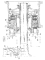
- the aircraft undercarriage comprises a caisson 1 in which a rod 2 slides.
- the caisson 1 is articulated to the aircraft and is stabilized in the low position by a bracing device (not shown).
- the rod 2 carries an axle 3 at the bottom, intended to receive a set of braked wheel 4.
- the rod 2 is prevented from rotating in the casing 1 by a compass 5 comprising two branches articulated respectively to the casing 1 and the rod 2.
- the braked wheel assembly comprises a wheel comprising a rim 6 which carries a tire not shown and which is mounted for rotation on the axle 3 by means of bearings 7.
- the stack of discs 8 comprises, alternately, rotor disks 8.1 (only one is referenced) which are constrained to rotate with the rim 6 by the effect of the engagement of appendices 9 with grooves 10 which extend inside the rim 6, and disks stators 8.2 (only one is referenced ) which are compelled to remain motionless by the effect of the engagement of appendices 11 received in grooves (not visible) of a torque recovery tube 12 screwed onto the axle 3.
- the stack of discs 8 extends between a fixed bottom 13 attached to the torque recovery tube 12, and a ring 14 also attached to the torque recovery tube 12 (by not shown mounting screws).
- the ring 14 carries modular electromechanical actuators 15 which each comprise a pusher 16 movable towards the pile of the discs 8 by means of an electric motor 18 (visible in FIG. 2) in order to apply a pressure on the stack of discs 8 .
- the actuators 15 are removably attached to the ring 14 (by means of fastening screws not shown) and are provided to be disassembled on the side of the ring 14 opposite the stack of disks 8, that is to say in the axial direction towards the box 1 and the rod 2.
- the actuators 15 comprise a housing portion 19 which extends through the ring 14.
- the arrows 17 in Figure 1 symbolize the disassembly direction of the actuators.
- the actuators 15a and 15b are, in their illustrated position of operation, directly opposite in the direction 17 of the structure of the landing gear, so that they are not removable.
- the actuators 15c and 15d By against the actuators 15c and 15d have a free space that extends opposite said actuators in the direction 17 for disassembly in said direction.
- These free spaces are symbolized in Figures 1 and 2 by zones delimited by mixed lines.
- the ring 14 To enable disassembly of the actuators 15a and 15b on the aircraft, it is provided according to the invention to relate the ring 14 to a circular cylindrical surface 20 of the torque recovery tube 12. To disassemble the actuators 15a or 15b, it is then sufficient to to remove the fastening screws securing the ring 14 to the recovery tube 12, then to rotate the ring 14 on the bearing surface 20 so as to bring the actuator 15a or the actuator 15b into a disassembly position (for example that occupied in operation by the actuator 15c or the actuator 15d). In this position, the actuators 15a or 15b can then be easily disassembled.
- the bearing surface 20 is particularly advantageous in that it allows guiding of the ring 14 in rotation which is then able to rotate easily without risk of falling on the axle 3.
- the ring gear 14 is no longer attached to the torque recovery tube 12, but directly to the axle 3.
- the bearing surface 20 is then fitted over a portion of the axle 3 to receive the rotating ring 14.
- the ring is not intended to be movable block after uncoupling. At least one actuator that can not be dismantled in its operating position is then mounted on a movable portion of the ring gear so as to bring said actuator into a disassembly position opposite which a free space extends.
- the actuators 115 are always intended to be disassembled in the axial direction, symbolized by the arrows 117.
- the axle 103 has a sufficient length so that a free space extends with respect to all the actuators, including those which are directly opposite the landing gear in the axial direction.
- the operating positions of all the actuators are therefore also disassembly positions. It is then possible to disassemble the actuators without the need to turn the crown 114.
- FIGS. 4 and 5 These drawbacks are avoided by virtue of a third particular embodiment of the invention illustrated in FIGS. 4 and 5 in which the references of the elements corresponding with those referenced above are further increased by a hundred.
- the actuators 215 and the crown 214 are provided so that the actuators can be dismounted in a direction substantially radial radial, coinciding with the axis of the wheel 206.
- the free spaces that receive the actuators in disassembled position are then located opposite the peripheral edge of the crown, which makes it possible to shorten the axle 203 to the bare minimum, while avoiding, here too, to provide a detachable crown.
- the ring 214 comprises U-shaped radial extensions 241 which form a guide both for the assembly and for the dismantling of an actuator 215.
- the housing portion 219 which extends through the ring 214 is delimited on the one hand by a flank 242 of the actuator housing and on the other hand by a flange 243.
- the flange 242 and the flange 243 are separated by a distance slightly greater than the thickness of the branches of the U of the radial extension 241, and the branches of the U are separated by a distance slightly greater than the diameter of the housing portion 219, so that the extension radial operates guidance not only in a lateral direction, but also in an axial direction.
- the guides 241 define a disassembly direction which is not concurrent with the central axis of the crown 214. This freedom allows all possible directions of disassembly directions of the actuators, they may even be different from one actuator to another.
- the guides 241 may not be rectilinear, but curved, at least in part.
- disassembly trajectory extends substantially in a plane perpendicular to the central axis of the ring, which coincides with the central axis of the wheel or stack of disks. It may be admitted, while remaining within the scope of the invention, that the disassembly trajectory comprises a slight axial component.
- the axial guide of the actuator 215 can be provided in several ways.
- the actuator 215 bears on the crown 214 only on the side thereof facing the stack of discs 208, via the flange 243.
- the guide so is not positive in the axial direction. Nevertheless, the support on one side is sufficient to allow easy installation of the actuator 215.
- the actuator bears against the crown 214 only on the opposite side to the stack of disks 208.
- the actuator comprises a flange 244 which is engaged in homologous grooves 245 cut in the branches of the U of the radial extension 241.
- the actuator comprises a groove 246 for receiving homologous studs 247 projecting inwardly from the branches of the U of the radial extension 241.
Landscapes
- Engineering & Computer Science (AREA)
- General Engineering & Computer Science (AREA)
- Mechanical Engineering (AREA)
- Braking Arrangements (AREA)
- Gear Transmission (AREA)
Applications Claiming Priority (2)
| Application Number | Priority Date | Filing Date | Title |
|---|---|---|---|
| FR0313335A FR2862280B1 (fr) | 2003-11-14 | 2003-11-14 | Atterrisseur, frein pour roue d'aeronef, ensemble de roue freinee d'aeronef, et procede de maintenance d'un tel atterrisseur |
| EP04292598A EP1533536B1 (de) | 2003-11-14 | 2004-11-03 | Bremse für ein Flugzeugrad, gebremstes Flugzeugrad, sowie Landegestell mit einem solchen Flugzeugrad |
Related Parent Applications (1)
| Application Number | Title | Priority Date | Filing Date |
|---|---|---|---|
| EP04292598A Division EP1533536B1 (de) | 2003-11-14 | 2004-11-03 | Bremse für ein Flugzeugrad, gebremstes Flugzeugrad, sowie Landegestell mit einem solchen Flugzeugrad |
Publications (2)
| Publication Number | Publication Date |
|---|---|
| EP1686280A1 true EP1686280A1 (de) | 2006-08-02 |
| EP1686280B1 EP1686280B1 (de) | 2008-08-20 |
Family
ID=34429991
Family Applications (2)
| Application Number | Title | Priority Date | Filing Date |
|---|---|---|---|
| EP06007941A Expired - Lifetime EP1686280B1 (de) | 2003-11-14 | 2004-11-03 | Landegestell, Bremse für ein Flugzeugrad, gebremstes Flugzeugrad, sowie Verfahren zur Wartung eines solchen Landegestells |
| EP04292598A Expired - Lifetime EP1533536B1 (de) | 2003-11-14 | 2004-11-03 | Bremse für ein Flugzeugrad, gebremstes Flugzeugrad, sowie Landegestell mit einem solchen Flugzeugrad |
Family Applications After (1)
| Application Number | Title | Priority Date | Filing Date |
|---|---|---|---|
| EP04292598A Expired - Lifetime EP1533536B1 (de) | 2003-11-14 | 2004-11-03 | Bremse für ein Flugzeugrad, gebremstes Flugzeugrad, sowie Landegestell mit einem solchen Flugzeugrad |
Country Status (8)
| Country | Link |
|---|---|
| US (1) | US8037971B2 (de) |
| EP (2) | EP1686280B1 (de) |
| AT (1) | ATE382804T1 (de) |
| BR (1) | BRPI0404977A (de) |
| CA (2) | CA2486735C (de) |
| DE (2) | DE602004016032D1 (de) |
| ES (2) | ES2298698T3 (de) |
| FR (1) | FR2862280B1 (de) |
Cited By (1)
| Publication number | Priority date | Publication date | Assignee | Title |
|---|---|---|---|---|
| CN107061560A (zh) * | 2016-12-22 | 2017-08-18 | 西安航空制动科技有限公司 | 一种刹车装置的钢承压盘组件 |
Families Citing this family (17)
| Publication number | Priority date | Publication date | Assignee | Title |
|---|---|---|---|---|
| US7527129B2 (en) | 2004-08-31 | 2009-05-05 | Honeywell International Inc. | Brake carrier having improved electromechanical actuator and mounting arrangement therefor |
| US7228945B2 (en) * | 2005-03-16 | 2007-06-12 | Hr Textron, Inc. | Techniques for employing electric brakes to control movement of rotatable components |
| EP2147226B1 (de) * | 2007-05-21 | 2013-07-03 | Goodrich Corporation | Reparatur einer eletroflugzeugbremse |
| EP2060821A1 (de) * | 2007-11-14 | 2009-05-20 | Goodrich Corporation | Flugzeugbremse und Verfahren mit elektromechanischen Aktuatormodulen |
| US8919504B2 (en) | 2009-12-03 | 2014-12-30 | Honeywell International Inc. | Brake actuator assembly with line replaceable motor features |
| US9815438B2 (en) | 2010-02-12 | 2017-11-14 | Honeywell International Inc. | Aircraft electric brake actuator assembly with line replaceable actuator brake |
| FR2990413B1 (fr) * | 2012-05-10 | 2014-06-06 | Messier Bugatti Dowty | Frein pour roue d'aeronef |
| FR2995587B1 (fr) * | 2012-09-17 | 2014-10-10 | Messier Bugatti Dowty | Procede de fixation d'un organe d'entrainement de roue d'aeronef sur l'atterrisseur portant la roue. |
| FR3021378B1 (fr) * | 2014-05-21 | 2016-06-03 | Messier Bugatti Dowty | Frein a disques pour roue d'aeronef |
| CN104443428B (zh) * | 2014-11-27 | 2016-08-24 | 航宇救生装备有限公司 | 常闭式可控液压刹车装置 |
| US20160304191A1 (en) * | 2015-04-16 | 2016-10-20 | Goodrich Corporation | Increased brake radius to improve rto performance |
| CN105173115A (zh) * | 2015-04-23 | 2015-12-23 | 南京王行航空附件维修工程有限公司 | 一种飞机起落架机轮组件的维修方法 |
| US9995353B2 (en) * | 2015-12-21 | 2018-06-12 | Goodrich Corporation | Modified actuator design to improve load distribution and damping |
| US10228030B2 (en) * | 2017-05-15 | 2019-03-12 | Goodrich Corporation | Multi-disk brake assembly with travel limit pin |
| CN108502205B (zh) * | 2018-05-29 | 2023-04-07 | 沈阳飞机工业(集团)有限公司 | 一种用于旋转框架的转动、止动装置及使用方法 |
| US20240383601A1 (en) * | 2023-05-18 | 2024-11-21 | DAWIN FRICTION, Ltd. | Wheel brake assembly for aircraft |
| CN120840883B (zh) * | 2025-09-22 | 2026-01-23 | 成都煜恒科技有限公司 | 一种飞机起落架拆卸装置 |
Citations (3)
| Publication number | Priority date | Publication date | Assignee | Title |
|---|---|---|---|---|
| US4175651A (en) * | 1977-03-28 | 1979-11-27 | Montalvo Edwin J Sr | Air/mercury actuation of brakes and clutches |
| US6095293A (en) | 1998-02-13 | 2000-08-01 | The B. F. Goodrich Company | Aircraft brake and method with electromechanical actuator modules |
| US6581730B1 (en) | 1999-09-13 | 2003-06-24 | Goodrich Corporation | Aircraft landing gear with integrated brake actuation system |
Family Cites Families (6)
| Publication number | Priority date | Publication date | Assignee | Title |
|---|---|---|---|---|
| US5862890A (en) * | 1996-01-16 | 1999-01-26 | Mcdonnell Douglas Corporation | Restrained aircraft brake apparatus |
| US6003640A (en) * | 1997-05-09 | 1999-12-21 | The B.F. Goodrich Company | Electronic braking system with brake wear measurement and running clearance adjustment |
| EP1214531B1 (de) * | 1999-09-13 | 2005-12-28 | Goodrich Corporation | Elektrisches bremsbetätigungsmodul für flugzeuge |
| EP1618313B1 (de) * | 2003-04-30 | 2020-12-02 | Goodrich Corporation | Elektrische bremse für ein luftfahrzeug |
| FR2859259B1 (fr) * | 2003-08-28 | 2006-02-03 | Messier Bugatti | Ensemble de freinage d'aeronef |
| DE602005019563D1 (de) * | 2004-06-04 | 2010-04-08 | Goodrich Corp | Messung und steuerung von position und kraft bei elektrischen bremsen |
-
2003
- 2003-11-14 FR FR0313335A patent/FR2862280B1/fr not_active Expired - Lifetime
-
2004
- 2004-11-02 CA CA002486735A patent/CA2486735C/fr not_active Expired - Fee Related
- 2004-11-02 CA CA2649112A patent/CA2649112C/fr not_active Expired - Fee Related
- 2004-11-03 DE DE602004016032T patent/DE602004016032D1/de not_active Expired - Lifetime
- 2004-11-03 ES ES04292598T patent/ES2298698T3/es not_active Expired - Lifetime
- 2004-11-03 EP EP06007941A patent/EP1686280B1/de not_active Expired - Lifetime
- 2004-11-03 DE DE602004010997T patent/DE602004010997T2/de not_active Expired - Lifetime
- 2004-11-03 AT AT04292598T patent/ATE382804T1/de not_active IP Right Cessation
- 2004-11-03 EP EP04292598A patent/EP1533536B1/de not_active Expired - Lifetime
- 2004-11-03 ES ES06007941T patent/ES2313483T3/es not_active Expired - Lifetime
- 2004-11-11 BR BR0404977-2A patent/BRPI0404977A/pt not_active IP Right Cessation
- 2004-11-12 US US10/986,212 patent/US8037971B2/en active Active
Patent Citations (3)
| Publication number | Priority date | Publication date | Assignee | Title |
|---|---|---|---|---|
| US4175651A (en) * | 1977-03-28 | 1979-11-27 | Montalvo Edwin J Sr | Air/mercury actuation of brakes and clutches |
| US6095293A (en) | 1998-02-13 | 2000-08-01 | The B. F. Goodrich Company | Aircraft brake and method with electromechanical actuator modules |
| US6581730B1 (en) | 1999-09-13 | 2003-06-24 | Goodrich Corporation | Aircraft landing gear with integrated brake actuation system |
Cited By (1)
| Publication number | Priority date | Publication date | Assignee | Title |
|---|---|---|---|---|
| CN107061560A (zh) * | 2016-12-22 | 2017-08-18 | 西安航空制动科技有限公司 | 一种刹车装置的钢承压盘组件 |
Also Published As
| Publication number | Publication date |
|---|---|
| FR2862280B1 (fr) | 2006-03-03 |
| CA2486735C (fr) | 2009-09-29 |
| US8037971B2 (en) | 2011-10-18 |
| DE602004010997T2 (de) | 2008-12-18 |
| CA2649112C (fr) | 2011-06-07 |
| EP1533536A1 (de) | 2005-05-25 |
| ES2313483T3 (es) | 2009-03-01 |
| DE602004016032D1 (de) | 2008-10-02 |
| CA2486735A1 (fr) | 2005-05-14 |
| ES2298698T3 (es) | 2008-05-16 |
| EP1686280B1 (de) | 2008-08-20 |
| EP1533536B1 (de) | 2008-01-02 |
| BRPI0404977A (pt) | 2005-07-19 |
| ATE382804T1 (de) | 2008-01-15 |
| US20050115778A1 (en) | 2005-06-02 |
| FR2862280A1 (fr) | 2005-05-20 |
| DE602004010997D1 (de) | 2008-02-14 |
| CA2649112A1 (fr) | 2005-05-14 |
Similar Documents
| Publication | Publication Date | Title |
|---|---|---|
| EP1533536B1 (de) | Bremse für ein Flugzeugrad, gebremstes Flugzeugrad, sowie Landegestell mit einem solchen Flugzeugrad | |
| EP2662283B1 (de) | Bremse für Fahrwerksrad eines Flugzeugs | |
| EP2361830B1 (de) | Landefahrwerk mit Vorrichtung zum Antrieb vom Fahrwerksrad | |
| EP2009244B1 (de) | Axiale Haltevorrichtung für Laufradschaufeln, die auf einer Rotorscheibe einer Strömungsmaschine montiert sind | |
| EP2876326B1 (de) | Verfahren zur Erneuerung und Verwendung von Bremsscheiben vom Typ rückwärtiger Stator mit Bremsklötzen, montierte Scheibe und entsprechender Scheibenstapel. | |
| EP2373872B1 (de) | Turbinenrad mit einer axialrückhaltevorrichtung, die schaufeln bezüglich einer scheibe verriegelt | |
| EP0080949A1 (de) | Scheibenbremse und Bremsbacken für eine derartige Bremse | |
| CA1233994A (fr) | Moyeu de roue a reducteur integre | |
| WO2015101484A2 (fr) | Dispositif de frein a tambour adaptable pour inclure un frein de stationnement traditionnel ou fonctionnant en mode duo servo | |
| EP1510719B1 (de) | Flugzeugbremseinheit | |
| EP3089900B1 (de) | Getriebeuntersetzung mit elektromotor für eine trommelbremse | |
| EP3025957B1 (de) | Verfahren zur befestigung eines stellglieds zum drehantrieb eines luftfahrzeugrads | |
| EP2647861B1 (de) | Verfahren zur Verwendung und Erneuerung einer Scheibe eines Bremsscheibenstapels einer Fahrzeugbremse | |
| FR3157349A1 (fr) | Ensemble roue et frein pour aéronef, et train d’atterrissage comprenant un tel ensemble | |
| EP0789444B1 (de) | Kraftfahrzeuggetriebe, versehen mit einem elektrischen Retarder | |
| CA3044094C (fr) | Systeme de freinage a disque et aeronef | |
| FR3147247A1 (fr) | Dispositif de compensation pour le verrouillage axial d’un premier élément tubulaire reçu à ajustement dans un deuxième élément tubulaire | |
| WO2025168362A1 (fr) | Dispositif de freinage à disque comprenant un passage pour des plaquettes de frein formé entre une couronne de support du disque et un support latéral | |
| FR3146960A1 (fr) | Dispositif de verrouillage axial d’un premier élement tubulaire reçu à ajustement dans un deuxième élément tubulaire | |
| FR3146959A1 (fr) | Dispositif de verrouillage axial d’un premier élément tubulaire reçu à ajustement dans un deuxième élément tubulaire | |
| FR3155507A1 (fr) | Roue freinée équipée d’un dispositif d’entraînement | |
| EP3469226A1 (de) | Reibungsbasierte geschwindigkeitssynchronisationsvorrichtung |
Legal Events
| Date | Code | Title | Description |
|---|---|---|---|
| PUAI | Public reference made under article 153(3) epc to a published international application that has entered the european phase |
Free format text: ORIGINAL CODE: 0009012 |
|
| AC | Divisional application: reference to earlier application |
Ref document number: 1533536 Country of ref document: EP Kind code of ref document: P |
|
| AK | Designated contracting states |
Kind code of ref document: A1 Designated state(s): AT BE BG CH CY CZ DE DK EE ES FI FR GB GR HU IE IS IT LI LU MC NL PL PT RO SE SI SK TR |
|
| 17P | Request for examination filed |
Effective date: 20070111 |
|
| 17Q | First examination report despatched |
Effective date: 20070219 |
|
| AKX | Designation fees paid |
Designated state(s): DE ES FR GB IT |
|
| GRAP | Despatch of communication of intention to grant a patent |
Free format text: ORIGINAL CODE: EPIDOSNIGR1 |
|
| GRAS | Grant fee paid |
Free format text: ORIGINAL CODE: EPIDOSNIGR3 |
|
| GRAA | (expected) grant |
Free format text: ORIGINAL CODE: 0009210 |
|
| AC | Divisional application: reference to earlier application |
Ref document number: 1533536 Country of ref document: EP Kind code of ref document: P |
|
| AK | Designated contracting states |
Kind code of ref document: B1 Designated state(s): DE ES FR GB IT |
|
| REG | Reference to a national code |
Ref country code: GB Ref legal event code: FG4D Free format text: NOT ENGLISH |
|
| REF | Corresponds to: |
Ref document number: 602004016032 Country of ref document: DE Date of ref document: 20081002 Kind code of ref document: P |
|
| REG | Reference to a national code |
Ref country code: ES Ref legal event code: FG2A Ref document number: 2313483 Country of ref document: ES Kind code of ref document: T3 |
|
| PLBE | No opposition filed within time limit |
Free format text: ORIGINAL CODE: 0009261 |
|
| STAA | Information on the status of an ep patent application or granted ep patent |
Free format text: STATUS: NO OPPOSITION FILED WITHIN TIME LIMIT |
|
| 26N | No opposition filed |
Effective date: 20090525 |
|
| REG | Reference to a national code |
Ref country code: FR Ref legal event code: CD Owner name: MESSIER-BUGATTI-DOWTY, FR Effective date: 20111013 Ref country code: FR Ref legal event code: CA Effective date: 20111013 |
|
| PGFP | Annual fee paid to national office [announced via postgrant information from national office to epo] |
Ref country code: ES Payment date: 20121127 Year of fee payment: 9 |
|
| PGFP | Annual fee paid to national office [announced via postgrant information from national office to epo] |
Ref country code: IT Payment date: 20131127 Year of fee payment: 10 |
|
| REG | Reference to a national code |
Ref country code: DE Ref legal event code: R082 Ref document number: 602004016032 Country of ref document: DE Representative=s name: SCHAUMBURG & PARTNER PATENTANWAELTE GBR, DE Ref country code: DE Ref legal event code: R082 Ref document number: 602004016032 Country of ref document: DE Representative=s name: SCHAUMBURG & PARTNER PATENTANWAELTE MBB, DE Ref country code: DE Ref legal event code: R082 Ref document number: 602004016032 Country of ref document: DE Representative=s name: SCHAUMBURG UND PARTNER PATENTANWAELTE MBB, DE |
|
| REG | Reference to a national code |
Ref country code: ES Ref legal event code: FD2A Effective date: 20150529 |
|
| PG25 | Lapsed in a contracting state [announced via postgrant information from national office to epo] |
Ref country code: ES Free format text: LAPSE BECAUSE OF NON-PAYMENT OF DUE FEES Effective date: 20131104 |
|
| PG25 | Lapsed in a contracting state [announced via postgrant information from national office to epo] |
Ref country code: IT Free format text: LAPSE BECAUSE OF NON-PAYMENT OF DUE FEES Effective date: 20141103 |
|
| REG | Reference to a national code |
Ref country code: FR Ref legal event code: PLFP Year of fee payment: 13 |
|
| REG | Reference to a national code |
Ref country code: FR Ref legal event code: CD Owner name: MESSIER BUGATTI DOWTY, FR Effective date: 20170518 |
|
| REG | Reference to a national code |
Ref country code: FR Ref legal event code: PLFP Year of fee payment: 14 |
|
| PGFP | Annual fee paid to national office [announced via postgrant information from national office to epo] |
Ref country code: GB Payment date: 20211020 Year of fee payment: 18 |
|
| GBPC | Gb: european patent ceased through non-payment of renewal fee |
Effective date: 20221103 |
|
| REG | Reference to a national code |
Ref country code: DE Ref legal event code: R081 Ref document number: 602004016032 Country of ref document: DE Owner name: SAFRAN LANDING SYSTEM, FR Free format text: FORMER OWNER: MESSIER-BUGATTI-DOWTY, VELIZY VILLACOUBLAY, FR Ref country code: DE Ref legal event code: R081 Ref document number: 602004016032 Country of ref document: DE Owner name: SAFRAN LANDING SYSTEM, FR Free format text: FORMER OWNER: MESSIER-BUGATTI, VELIZY VILLACOUBLAY, FR |
|
| PG25 | Lapsed in a contracting state [announced via postgrant information from national office to epo] |
Ref country code: GB Free format text: LAPSE BECAUSE OF NON-PAYMENT OF DUE FEES Effective date: 20221103 |
|
| PGFP | Annual fee paid to national office [announced via postgrant information from national office to epo] |
Ref country code: FR Payment date: 20231019 Year of fee payment: 20 Ref country code: DE Payment date: 20231019 Year of fee payment: 20 |
|
| REG | Reference to a national code |
Ref country code: DE Ref legal event code: R071 Ref document number: 602004016032 Country of ref document: DE |