EP1686289A2 - Roue dentée sans jeu en résine - Google Patents
Roue dentée sans jeu en résine Download PDFInfo
- Publication number
- EP1686289A2 EP1686289A2 EP06250517A EP06250517A EP1686289A2 EP 1686289 A2 EP1686289 A2 EP 1686289A2 EP 06250517 A EP06250517 A EP 06250517A EP 06250517 A EP06250517 A EP 06250517A EP 1686289 A2 EP1686289 A2 EP 1686289A2
- Authority
- EP
- European Patent Office
- Prior art keywords
- tooth
- gear
- gears
- pair
- overhang
- Prior art date
- Legal status (The legal status is an assumption and is not a legal conclusion. Google has not performed a legal analysis and makes no representation as to the accuracy of the status listed.)
- Withdrawn
Links
- 239000011347 resin Substances 0.000 title description 3
- 229920005989 resin Polymers 0.000 title description 3
- 238000010586 diagram Methods 0.000 description 8
- 230000005540 biological transmission Effects 0.000 description 6
- 230000013011 mating Effects 0.000 description 3
- 229930182556 Polyacetal Natural products 0.000 description 2
- 239000004952 Polyamide Substances 0.000 description 2
- 239000004734 Polyphenylene sulfide Substances 0.000 description 2
- 238000001746 injection moulding Methods 0.000 description 2
- 239000000463 material Substances 0.000 description 2
- 239000002991 molded plastic Substances 0.000 description 2
- 230000002093 peripheral effect Effects 0.000 description 2
- 229920002647 polyamide Polymers 0.000 description 2
- -1 polybutylene Polymers 0.000 description 2
- 229920001748 polybutylene Polymers 0.000 description 2
- 229920006324 polyoxymethylene Polymers 0.000 description 2
- 229920000069 polyphenylene sulfide Polymers 0.000 description 2
- 238000009499 grossing Methods 0.000 description 1
- 238000005461 lubrication Methods 0.000 description 1
- 238000004519 manufacturing process Methods 0.000 description 1
- 239000002184 metal Substances 0.000 description 1
- 230000035939 shock Effects 0.000 description 1
Images


Classifications
-
- F—MECHANICAL ENGINEERING; LIGHTING; HEATING; WEAPONS; BLASTING
- F16—ENGINEERING ELEMENTS AND UNITS; GENERAL MEASURES FOR PRODUCING AND MAINTAINING EFFECTIVE FUNCTIONING OF MACHINES OR INSTALLATIONS; THERMAL INSULATION IN GENERAL
- F16H—GEARING
- F16H55/00—Elements with teeth or friction surfaces for conveying motion; Worms, pulleys or sheaves for gearing mechanisms
- F16H55/02—Toothed members; Worms
- F16H55/17—Toothed wheels
- F16H55/18—Special devices for taking up backlash
-
- Y—GENERAL TAGGING OF NEW TECHNOLOGICAL DEVELOPMENTS; GENERAL TAGGING OF CROSS-SECTIONAL TECHNOLOGIES SPANNING OVER SEVERAL SECTIONS OF THE IPC; TECHNICAL SUBJECTS COVERED BY FORMER USPC CROSS-REFERENCE ART COLLECTIONS [XRACs] AND DIGESTS
- Y10—TECHNICAL SUBJECTS COVERED BY FORMER USPC
- Y10S—TECHNICAL SUBJECTS COVERED BY FORMER USPC CROSS-REFERENCE ART COLLECTIONS [XRACs] AND DIGESTS
- Y10S74/00—Machine element or mechanism
- Y10S74/10—Polymer digest - plastic gears
-
- Y—GENERAL TAGGING OF NEW TECHNOLOGICAL DEVELOPMENTS; GENERAL TAGGING OF CROSS-SECTIONAL TECHNOLOGIES SPANNING OVER SEVERAL SECTIONS OF THE IPC; TECHNICAL SUBJECTS COVERED BY FORMER USPC CROSS-REFERENCE ART COLLECTIONS [XRACs] AND DIGESTS
- Y10—TECHNICAL SUBJECTS COVERED BY FORMER USPC
- Y10T—TECHNICAL SUBJECTS COVERED BY FORMER US CLASSIFICATION
- Y10T74/00—Machine element or mechanism
- Y10T74/19—Gearing
- Y10T74/19623—Backlash take-up
-
- Y—GENERAL TAGGING OF NEW TECHNOLOGICAL DEVELOPMENTS; GENERAL TAGGING OF CROSS-SECTIONAL TECHNOLOGIES SPANNING OVER SEVERAL SECTIONS OF THE IPC; TECHNICAL SUBJECTS COVERED BY FORMER USPC CROSS-REFERENCE ART COLLECTIONS [XRACs] AND DIGESTS
- Y10—TECHNICAL SUBJECTS COVERED BY FORMER USPC
- Y10T—TECHNICAL SUBJECTS COVERED BY FORMER US CLASSIFICATION
- Y10T74/00—Machine element or mechanism
- Y10T74/19—Gearing
- Y10T74/19633—Yieldability in gear trains
-
- Y—GENERAL TAGGING OF NEW TECHNOLOGICAL DEVELOPMENTS; GENERAL TAGGING OF CROSS-SECTIONAL TECHNOLOGIES SPANNING OVER SEVERAL SECTIONS OF THE IPC; TECHNICAL SUBJECTS COVERED BY FORMER USPC CROSS-REFERENCE ART COLLECTIONS [XRACs] AND DIGESTS
- Y10—TECHNICAL SUBJECTS COVERED BY FORMER USPC
- Y10T—TECHNICAL SUBJECTS COVERED BY FORMER US CLASSIFICATION
- Y10T74/00—Machine element or mechanism
- Y10T74/19—Gearing
- Y10T74/19949—Teeth
-
- Y—GENERAL TAGGING OF NEW TECHNOLOGICAL DEVELOPMENTS; GENERAL TAGGING OF CROSS-SECTIONAL TECHNOLOGIES SPANNING OVER SEVERAL SECTIONS OF THE IPC; TECHNICAL SUBJECTS COVERED BY FORMER USPC CROSS-REFERENCE ART COLLECTIONS [XRACs] AND DIGESTS
- Y10—TECHNICAL SUBJECTS COVERED BY FORMER USPC
- Y10T—TECHNICAL SUBJECTS COVERED BY FORMER US CLASSIFICATION
- Y10T74/00—Machine element or mechanism
- Y10T74/19—Gearing
- Y10T74/19949—Teeth
- Y10T74/19958—Bevel
-
- Y—GENERAL TAGGING OF NEW TECHNOLOGICAL DEVELOPMENTS; GENERAL TAGGING OF CROSS-SECTIONAL TECHNOLOGIES SPANNING OVER SEVERAL SECTIONS OF THE IPC; TECHNICAL SUBJECTS COVERED BY FORMER USPC CROSS-REFERENCE ART COLLECTIONS [XRACs] AND DIGESTS
- Y10—TECHNICAL SUBJECTS COVERED BY FORMER USPC
- Y10T—TECHNICAL SUBJECTS COVERED BY FORMER US CLASSIFICATION
- Y10T74/00—Machine element or mechanism
- Y10T74/19—Gearing
- Y10T74/19949—Teeth
- Y10T74/19963—Spur
- Y10T74/19972—Spur form
Definitions
- the present invention relates to a gearing apparatus for transmitting a rotational motion between two shafts by assembling a pair of resin-made toothed wheels (it will be referred to as gears hereinafter) to engage opposite teeth with each other, and in particular, to a resin-made gearing apparatus for absorbing a given amount of backlash appearing upon engagement of the pair of gears by a backlash absorbing section and also for reducing the deformation and stress of the backlash absorbing section.
- the resin-made gearing apparatus of this type is characterized in that it is lightweight compared with a metal gearing apparatus, and also is capable to be used without the lubrication due to the self-lubricity thereof and in low noise. Further, the resin-made gearing apparatus, such as a molded plastic gear or the like, has a characteristic of high mass-production to achieve the reduction of product cost. Therefore, in recent years, the molded plastic gear has been widely used for a gear train in an ink jet printer, a gear train in a power transmission section of an automotive component or in a precision machine or instrument, and the like.
- a clearance (play) called a backlash is disposed between teeth oppositely mating with each other in the assembly of a pair of gears.
- This backlash is disposed for preventing the friction of a tooth surface of the gear due to a tooth profile error, an assembly error or the like, and also, for smoothing the meshing of the gear teeth.
- a gear 50 is formed with a fin portion 52 on each of both tooth flanks on one end side in a tooth width direction of each tooth 51, to be in contact with a mated or meshed gear, thereby absorbing any shock at the time coming into mating contact by the deformation of the fin portion 52 (refer to Japanese Unexamined Utility Model Publication No. 55-100745 (Fig. 1 and Fig. 3)).
- the elastically deformable fin portion 52 is formed only on each end portion in the tooth width direction of each tooth, in one of the assembly of the pair of gears, but any contrivance is not provided on each tooth of the other meshed gear. Therefore, the fin portion 52 on the tooth in the one gear may be in direct contact with a tooth flank of the tooth of the other meshed gear so that both gears must be subjected to a high stress. Namely, although the fin portion 52 on each of the end portions in the tooth width direction in the one gear is elastically deformable, the tooth flank of each tooth in the other meshed gear forms a power transmitting plane which is not elastically deformed.
- the fin portion 52 in the one gear may come in contact with the power transmission plane, to be deformed to an extent exceeding an elastic limit range.
- the high stress mainly acts on the folded portion, and in an extreme case, it is deemed that the fin portion 52 of the tooth in the one gear is broken.
- an object of the present invention is to provide a resin-made gearing apparatus for absorbing a given amount of backlash by a backlash absorbing section upon engagement of a pair of gears by meshing, and also for reducing a deformation and stress of the backlash absorbing section.
- a resin-made gearing apparatus for transmitting a rotational motion between two shafts by an engagement of a pair of resin-made gears arranged to have opposite teeth meshed with each other, comprising a configuration wherein only one tooth flank side of each tooth in one of the gears is provided with an overhang section that is disposed on at least one of end portions in a direction of tooth width, and overhangs diagonally from the one tooth flank side toward an adjacent tooth side to eliminate a backlash during a time when the pair of gears are meshed with each other; an end portion in a direction of a tooth width of each tooth of the other gear, corresponding to the overhang section of the each tooth of the one gear, is provided with a lightening section that is disposed at an end face on the side of the end portion and inside a profile of the each tooth of the other gear; and the overhang section of the one gear as well as the lightening section of the other
- only the one tooth flank side of the one gear is provided with the overhang section that is disposed on at least one of the end portions in the tooth width direction, and overhangs diagonally from the one tooth flank side toward the adjacent tooth side, and the end portion in the tooth width direction of each tooth of the other gear is provided with the lightening section that is disposed at the end face on the side of the end portion, corresponding to the overhang section of the one gear, so that when the opposite teeth of the pair of gears are meshed with each other due to the rotation of the pair off gears, the overhang section of the one gear is elastically deformed and also the lightening section of the other gear is elastically deformed so as to absorb the given amount of backlash.
- a resin-made gearing apparatus for transmitting a rotational motion between two shafts by an engagement of a pair of resin-made gears arranged to have opposite teeth meshed with each other, comprising a configuration wherein both tooth flank sides of each tooth of one of the gears are provided with overhang sections that are disposed on at least one of end portions in a direction of tooth width, each of which overhangs diagonally from each of the both tooth flank sides toward an adjacent tooth side to eliminate a backlash during a time when the pair of gears are meshed with each other; an end portion in a direction of a tooth width of each tooth of the other gear, corresponding to the overhang sections of the each tooth of the one gear, is provided with a lightening section that is disposed at an end face on the side of the end portion and inside a profile of the each tooth of the other gear; and the overhang sections of the one gear as well as the lightening section of the other gear are elastically deformed due to mesh
- both tooth flank sides of each tooth in the one gear are provided with the overhang sections that are disposed on at least one of the end portions in the tooth width direction, each of which overhangs diagonally from the one tooth flank side toward the adjacent tooth side, and the end portion in the tooth width direction of each tooth in the other gear is provide with the lightening section that is disposed at the end face on the side of each end portion corresponding to the overhang section of the one gear, so that when the opposite teeth of the pair of gears are meshed with each other, the overhang sections of the one gear are elastically deformed and also the lightening section of the other gear is elastically deformed so as to absorb the backlash.
- a resin-made gearing apparatus for transmitting a rotational motion between two shafts by an engagement of a pair of resin-made gears arranged to have opposite teeth meshed with each other, comprising a configuration wherein only one tooth flank side of each tooth of one of the gears is provided with an overhang section that is disposed on at least one of end portions in a direction of tooth width, and overhangs diagonally from the one tooth flank side toward an adjacent tooth side to eliminate a backlash during a time when the pair of gears are meshed with each other; only one tooth flank side of each tooth of the other gear is provided with an opposite overhang section that is disposed on an end portion, corresponding to the overhang section of the each tooth of the one gear, and overhangs diagonally from the one tooth flank side toward adjacent tooth side; and the overhang section of the one gear as well as the opposite overhang section of the other gear are elastically deformed due to meshing of the teeth of the pair of gears during the rotation
- only the one tooth flank side of each tooth in the one gear is provided with the overhang section that is disposed on at least one of the end portions in the tooth width direction, and overhangs diagonally from the one tooth flank side toward the adjacent tooth side
- only the one tooth flank side of each tooth in the other gear is provided with the opposite overhang section that is disposed on the end portion, corresponding to the overhang section of the one gear, and overhangs diagonally from the one tooth flank side toward the adjacent tooth side, so that when the opposite teeth of the pair of gears are meshed with each other during the rotation of the pair of gears, the overhang section of the one gear is elastically deformed and also the opposite overhang section of the other gear is elastically deformed so as to absorb the backlash.
- a resin-made gearing apparatus for transmitting a rotational motion between two shafts by an engagement of a pair of resin-made gears arranged to have opposite teeth meshed with each other, comprising a configuration wherein both tooth flank sides of each tooth of one of the gears are provided with overhang sections that are disposed on at least one of end portions in a direction of tooth width, each of which overhangs diagonally from each of the both tooth flank sides toward an adjacent tooth side to eliminate a backlash during a time when the pair of gears are meshed with each other; both tooth flank sides of each tooth of the other gear are provided with opposite overhang sections that are disposed on end portion, corresponding to the overhang sections of the each tooth of the one gear, each of which overhangs diagonally from each of the both tooth flank sides toward adjacent tooth sides; and the overhang sections of the one gear as well as the opposite overhang sections of the other gear are elastically deformed due to meshing of the teeth of the pair of gears during the rotation of the
- both tooth flank sides of each tooth in one of the gears are provided with the overhang sections that are disposed on at least one of end portions in a tooth width direction, each of which overhangs diagonally from each of both tooth flank sides toward the adjacent tooth side, and both tooth flank sides of each tooth in the other gear are provided with the opposite overhang sections that are disposed on each end portion, corresponding to the overhang section of the one gear, each of which overhangs diagonally from each of both tooth flank sides toward the adjacent tooth side, so that when the opposite teeth of the pair of gears are meshed with each other, the overhang sections of the one gear are elastically deformed and also the opposite overhang sections of the other gear are elastically deformed so as to absorb the backlash.
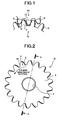
- Fig. 1 is a diagram showing an embodiment of a resin-made gearing apparatus according to the present invention, for explaining a main part of the apparatus in a state where a pair of gears is mated with each other.
- This resin-made gear apparatus is provided for transmitting a rotational motion between two shafts by an engagement of a pair of resin-made gears having opposite teeth meshed with each other, and is configured by combining one gear G 1 and the other gear G 2 .
- the one gear G 1 is, for example a gear having a small number of teeth, and is usually called a pinion.
- the other gear G 2 is, for example a gear having a large number of teeth, and is usually called a main gear.
- an overhang section C is disposed on both of or one of end portions in a direction of tooth width (it will be referred to as a tooth width direction herein after), which overhangs diagonally from the one tooth flank side to the adjacent tooth side to eliminate a backlash during a time when the pair of gears G 1 and G 2 is in meshed engagement with each other due to the rotation of the pair of gears G 1 and G 2 .
- both of or one of end portions in a tooth width direction of each tooth are provided with a lightening section D that is provided as an unfilled portion disposed inside a tooth profile of each tooth on an end face on the side of the end portion corresponding to the overhang section C of the one gear G 1 .
- the gear G 1 is a spur gear which is formed by the injection molding using a resin material, for example, polyacetal, polyamide, polyphenylene sulfide, polybutylene terephthalete or the like.
- a resin material for example, polyacetal, polyamide, polyphenylene sulfide, polybutylene terephthalete or the like.
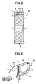
- a plurality of teeth 2 is formed on the outer peripheral side of a web 3 of approximately circular plate shape, and a shaft hole 4 for fixing therein a rotating shaft is bored at the central portion of the web 3.
- each tooth 2 has a predetermined tooth width in an axial direction.
- each tooth flank 6 side of each tooth 2 of the gear G 1 is provided with a thin overhang member 5 serving as the overhang section C and disposed on both end portions in the tooth width direction, respectively.
- This overhang member 5 serves as a backlash absorbing section for eliminating the backlash during a time when the pair of gears G 1 and G 2 is in a meshed engagement with each other, and overhangs diagonally from the one tooth flank 6 side of the tooth 2 toward the adjacent tooth 2.
- the overhang member 5 having the approximately uniform thickness is formed to protrude from a tooth crest 7 toward a bottom land 8, and a protruding amount of the overhang member 5 is gradually increased toward both ends in the tooth width direction.
- This overhang member 5 protrudes toward the adjacent tooth 2 by a dimension approximately same the backlash which is set between the tooth of the gear G 1 and at least the tooth of the meshed gear G 2 , and a clearance 11 is formed between an end portion 10 of the tooth 2 and the overhang member 5.
- the clearance 11 has a depth thereof measured in the tooth width direction, which extends toward a position approximately coincident with a starting position P1 of the overhang member 5 and also extends from the tooth crest 7 to the bottom land 8 along the one tooth flank 6.
- the other tooth flank 12 (on which the overhang member 5 is not formed) of the tooth 2 serves as a power transmission plane which is in contact with the tooth flank of the meshed gear G 2 to transmit the rotational motion.
- the gear G 1 is rotated in reverse to a main rotational direction to transmit the rotational motion, if the overhang member 5 is pressed to be deformed by the tooth flank of the meshed gear G 2 , the deformed overhang member 5 is accommodated in the clearance 11.
- the overhang member 5 does not protrude from the one tooth flank 6 toward the outside, so that high rigid tooth flanks can be in contact with each other, to thereby enable the accurate transmission of the rotational motion even in the case where the gear G 1 is rotated in reverse.
- a dimension L from an edge 13 in the tooth width direction to the starting position P1, of the overhang member 5 is determined to be an optimum dimension based on a tooth width dimension, the thickness of the overhang member 5 and the like. For example, in a gear whose module is about 0.5mm to 2.0mm, if the thickness of the overhang member 5 is about 0.2mm, the dimension L is determined to be about 1/6 to 1/4 of the tooth width dimension. Note, the depth of cut of the clearance 11 is determined to have a dimension approximately same as the dimension L of the overhang member 5.
- the overhang member 5 is disposed on each of the end portions in the tooth width direction, on the one tooth flank 6 side of the tooth 2.
- the present invention is not limited thereto, and the overhang member 5 may be provided to be disposed only on either one of the end portions in the tooth width direction.
- the gear G 2 is also a spur gear which is formed by the injection molding using a resin material, for example, polyacetal, polyamide, polyphenylene sulfide, polybutylene terephthalete or the like.
- a resin material for example, polyacetal, polyamide, polyphenylene sulfide, polybutylene terephthalete or the like.
- a plurality of teeth 15 is formed on the outer peripheral side of a web 14 of approximately circular plate shape, and each tooth 15 has the predetermined tooth thickness along a pitch circle thereof.
- a lightening section D formed as an unfilled portion is disposed in a teeth profile of the tooth 15.
- the lightening section D serves as a backlash absorbing section, which elastically deforms the overhang section C of the one gear G 1 and also elastically deforms the end portion of the other gear G 2 to eliminate a given amount of backlash, when the opposite teeth of the pair of gears G 1 and G 2 are meshed with each other, and is cut out into a wedge shape for example, by a predetermined depth from each end face of both end portions of the tooth 15 into the inside thereof in the tooth width direction of that tooth 15.
- the lightening section D is made wider toward the end face of each end portion in the tooth width direction of the tooth 15, so that the remained member becomes thin to be deformable.
- numeral 17 denotes a tooth crest of the tooth 15 and numeral 18 denotes a bottom land of the tooth 15.
- the lightening section D is disposed on each end face of both end portions in the tooth width direction of the tooth 15.
- the present invention is not limited thereto, and the lightening section D may be disposed only on the end face on the end portion side corresponding to the overhang member 5 of the one gear G 1 .
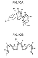
- Figures 7 and 8 are explanation diagrams showing a second embodiment of the shape of the one gear G 1 .
- a cavity portion 25 is formed on each of end portion sides in the tooth width direction of the tooth 2, and a thin portion 26 is formed so as to surround the cavity portion 25.
- a part of the thin portion 26, which is disposed on the one tooth flank 6 side, is formed so as to overhang toward the adjacent tooth 2 side, to thereby be used as a thin overhang member 27.
- this overhang member 27 is formed to protrude from the tooth crest 7 toward the bottom land 8 so as to have the approximately uniform thickness, and a protruding amount of the overhang member 27 is gradually increased toward each end in the tooth width direction.
- a dimension of depth of the cavity portion 25 is same as the depth of cut of the clearance 11 as shown in Fig. 4, and the thickness of the overhang member 27 is same as the thickness of the overhang member 5 shown in Fig. 4.
- the overhang member 27 is disposed on each end portion in the tooth width direction, on the one tooth flank 6 side of the tooth 2.
- the present invention is not limited thereto, and the overhang member 27 may be disposed only on either one of the end portions in the tooth width direction.
- Figure 9 is an explanation diagram showing a third embodiment of the shape of the one gear G 1 .
- a thin overhang member 33 is formed to overhang to the adjacent tooth 2 side, respectively.
- the overhang member 33 which is formed similarly to the overhang member 27 on the side of the one tooth flank 6 as shown in Fig. 7, is also formed on the side of the other tooth flank 12.
- an overhanging amount of each overhang member 33 can be made only approximately a half of an overhanging amount of the overhang member 27 as shown in Fig. 7.
- the overhang member 33 is disposed on each of the end portions in the tooth width direction, on each side of the one tooth flank 6 and of the other tooth flank 12 of the tooth 2.
- the present invention is not limited thereto, and the overhang member 33 may be disposed only on either one end portion in the tooth width direction.
- the lightening section D is disposed as an unfilled portion formed in the tooth profile of the tooth 15 on the end portion in the tooth width direction of the tooth 15 of the other gear G 2 .
- the present invention is not limited thereto, and similarly to Fig. 4, Fig. 7 or Fig.
- an opposite overhang member (not shown in the figure), which overhangs diagonally from the one tooth flank side or each tooth flank side toward the adjacent tooth side, on the end portion corresponding to each of the overhang members 5, 27 and 33 of the one gear G 1 .
- the overhang members 5, 27 and 33 of the one gear G 1 , and the opposite overhang members of the other gear G 2 absorb the backlash, and therefore, the overhang amount of each of the overhang members 5, 27 and 33 of the one gear G 1 can be reduced to only approximately a half.
Landscapes
- Engineering & Computer Science (AREA)
- General Engineering & Computer Science (AREA)
- Mechanical Engineering (AREA)
- Gears, Cams (AREA)
Applications Claiming Priority (1)
| Application Number | Priority Date | Filing Date | Title |
|---|---|---|---|
| JP2005023667A JP4640777B2 (ja) | 2005-01-31 | 2005-01-31 | 樹脂製歯車装置 |
Publications (2)
| Publication Number | Publication Date |
|---|---|
| EP1686289A2 true EP1686289A2 (fr) | 2006-08-02 |
| EP1686289A3 EP1686289A3 (fr) | 2009-12-23 |
Family
ID=36223382
Family Applications (1)
| Application Number | Title | Priority Date | Filing Date |
|---|---|---|---|
| EP06250517A Withdrawn EP1686289A3 (fr) | 2005-01-31 | 2006-01-31 | Roue dentée sans jeu en résine |
Country Status (4)
| Country | Link |
|---|---|
| US (1) | US7526977B2 (fr) |
| EP (1) | EP1686289A3 (fr) |
| JP (1) | JP4640777B2 (fr) |
| CN (1) | CN100564938C (fr) |
Families Citing this family (17)
| Publication number | Priority date | Publication date | Assignee | Title |
|---|---|---|---|---|
| JP4470163B2 (ja) * | 2003-09-03 | 2010-06-02 | 株式会社エンプラス | 成形プラスチック歯車及びこれを使用した間歇回転伝達機構、成形プラスチック歯車の使用方法 |
| JP4640777B2 (ja) * | 2005-01-31 | 2011-03-02 | 株式会社エンプラス | 樹脂製歯車装置 |
| JP5299967B2 (ja) * | 2008-08-06 | 2013-09-25 | 株式会社エンプラス | 射出成形樹脂フェースギヤ |
| GB0821985D0 (en) * | 2008-12-03 | 2009-01-07 | Rolls Royce Plc | A gear |
| KR100945193B1 (ko) * | 2009-06-10 | 2010-03-03 | 주식회사 세진아이지비 | 동력전달장치 |
| KR101753418B1 (ko) * | 2009-06-25 | 2017-07-03 | 섀플러 테크놀로지스 아게 운트 코. 카게 | 시동 전 백래시를 극복하기 위한 클러치 구동부를 구비한 파워 트레인 |
| JP5430538B2 (ja) * | 2010-03-09 | 2014-03-05 | ジヤトコ株式会社 | ギア構造 |
| US8578807B2 (en) * | 2011-04-21 | 2013-11-12 | The Penn State Research Foundation | High speed gear sized and configured to reduce windage loss |
| JP5755545B2 (ja) * | 2011-10-11 | 2015-07-29 | トヨタ自動車株式会社 | 歯車及び変速装置 |
| DE102013021824A1 (de) * | 2013-12-21 | 2015-06-25 | Valeo Schalter Und Sensoren Gmbh | Sensorvorrichtung zum Erfassen eines Positionswinkels eines drehbaren Bauteils eines Kraftfahrzeugs und Kraftfahrzeug |
| DE102014102982B3 (de) * | 2014-03-06 | 2015-03-05 | Horst Scholz Gmbh & Co. Kg | Lenkwinkelsensor |
| GB2547035B (en) | 2016-02-05 | 2019-03-13 | Ford Global Tech Llc | Gear assembly |
| GB201611572D0 (en) * | 2016-07-01 | 2016-08-17 | Victrex Mfg Ltd | Polymeric materials |
| EP3775622A4 (fr) * | 2018-04-13 | 2021-04-07 | 1-Up Design and Consulting, LLC | Procédé de réduction de bruit d'engrenage |
| JP7339076B2 (ja) * | 2019-08-30 | 2023-09-05 | ファナック株式会社 | 軽量歯車とその製造方法、歯車列の製造方法およびロボット |
| JP2021134801A (ja) * | 2020-02-24 | 2021-09-13 | 株式会社デンソー | アクチュエータ |
| JP7735284B2 (ja) * | 2020-09-02 | 2025-09-08 | 日本精工株式会社 | ステアリングシャフト及びステアリングシャフトの製造方法 |
Citations (1)
| Publication number | Priority date | Publication date | Assignee | Title |
|---|---|---|---|---|
| JPS55100745U (fr) | 1979-01-09 | 1980-07-14 |
Family Cites Families (17)
| Publication number | Priority date | Publication date | Assignee | Title |
|---|---|---|---|---|
| JPS5469257U (fr) * | 1977-10-25 | 1979-05-17 | ||
| JPS5598849U (fr) * | 1978-12-29 | 1980-07-09 | ||
| US4274135A (en) | 1979-01-26 | 1981-06-16 | Westinghouse Electric Corp. | Gating circuit for high voltage thyristor strings |
| JPS5610860A (en) * | 1979-07-04 | 1981-02-03 | Matsushita Electric Ind Co Ltd | Gear |
| JPS56155157U (fr) * | 1980-04-22 | 1981-11-19 | ||
| JPS58127246U (ja) * | 1982-02-23 | 1983-08-29 | カルソニックカンセイ株式会社 | 騒音防止歯車 |
| JPS59169460U (ja) * | 1983-04-28 | 1984-11-13 | 松下電工株式会社 | 歯車 |
| JPS6230056U (fr) * | 1985-08-08 | 1987-02-23 | ||
| JPH02304243A (ja) * | 1989-05-19 | 1990-12-18 | Toshiba Corp | 歯車 |
| US5870928A (en) * | 1997-05-08 | 1999-02-16 | Cummins Engine Company, Inc. | Anti-lash gear with alignment device |
| JPH1134466A (ja) * | 1997-07-23 | 1999-02-09 | Riso Kagaku Corp | 版胴駆動用係脱式歯車装置 |
| US6354395B1 (en) * | 1997-08-04 | 2002-03-12 | Delphi Technologies, Inc. | Delashed worm gear assembly and electric power assist apparatus |
| JP4135794B2 (ja) * | 2001-09-14 | 2008-08-20 | 株式会社エンプラス | 射出成形プラスチックギヤ |
| JP4016886B2 (ja) * | 2003-05-28 | 2007-12-05 | 株式会社ジェイテクト | 電動パワーステアリング装置 |
| JP4470163B2 (ja) * | 2003-09-03 | 2010-06-02 | 株式会社エンプラス | 成形プラスチック歯車及びこれを使用した間歇回転伝達機構、成形プラスチック歯車の使用方法 |
| EP1555584A1 (fr) * | 2004-01-13 | 2005-07-20 | Rolex S.A. | Mobile denté à rattrapage de jeu, engrenage et utilisation de cet engrenage |
| JP4640777B2 (ja) * | 2005-01-31 | 2011-03-02 | 株式会社エンプラス | 樹脂製歯車装置 |
-
2005
- 2005-01-31 JP JP2005023667A patent/JP4640777B2/ja not_active Expired - Fee Related
-
2006
- 2006-01-27 CN CNB2006100029096A patent/CN100564938C/zh not_active Expired - Fee Related
- 2006-01-31 EP EP06250517A patent/EP1686289A3/fr not_active Withdrawn
- 2006-01-31 US US11/342,830 patent/US7526977B2/en not_active Expired - Fee Related
Patent Citations (1)
| Publication number | Priority date | Publication date | Assignee | Title |
|---|---|---|---|---|
| JPS55100745U (fr) | 1979-01-09 | 1980-07-14 |
Also Published As
| Publication number | Publication date |
|---|---|
| JP2006207770A (ja) | 2006-08-10 |
| CN100564938C (zh) | 2009-12-02 |
| JP4640777B2 (ja) | 2011-03-02 |
| CN1815059A (zh) | 2006-08-09 |
| US20060201271A1 (en) | 2006-09-14 |
| US7526977B2 (en) | 2009-05-05 |
| EP1686289A3 (fr) | 2009-12-23 |
Similar Documents
| Publication | Publication Date | Title |
|---|---|---|
| US7526977B2 (en) | Resin-made gearing apparatus | |
| US7406892B2 (en) | Plastic molded gear, and intermittent rotation transmission device and gear train using same | |
| JP4919497B2 (ja) | 樹脂製歯車 | |
| US20070137355A1 (en) | Gears and gearing apparatus | |
| EP3306132A1 (fr) | Dispositif d'engrenage à ondes de déformation doté d'un engrènement composé impliquant la congruence des surfaces de dents | |
| US20150082930A1 (en) | Gear mechanism and manufacturing method of gear mechanism | |
| JP4665516B2 (ja) | 遊星歯車機構およびその製造方法 | |
| CN108474453A (zh) | 2个应力纯分离的波动齿轮装置 | |
| JP4375723B2 (ja) | 歯車 | |
| US8240227B2 (en) | Injection-molded resin face gear | |
| JP5729965B2 (ja) | はすば歯車 | |
| JPH08312755A (ja) | 平行軸歯車対 | |
| JP4375720B2 (ja) | 樹脂歯車 | |
| EP0476802A1 (fr) | Pair d'engrenages | |
| US20050139029A1 (en) | Resin backlashless gear and resin backlashless rack | |
| JPS6121640Y2 (fr) | ||
| US7992462B2 (en) | Resin double-helical gear | |
| CN112119243A (zh) | 波动齿轮装置 | |
| JP4618916B2 (ja) | 回転伝達誤差低減歯車の設計方法およびその方法により設計された歯車 | |
| US8033196B2 (en) | Resin double helical gear pair | |
| JP4282423B2 (ja) | 樹脂製やまば歯車 | |
| CN101059159B (zh) | 减速装置的等速连结构造 | |
| JP4979218B2 (ja) | 歯車及び歯車装置 | |
| KR100955093B1 (ko) | 정밀 감속기 및 정밀 감속기의 설계방법 | |
| JP4697887B2 (ja) | 一対の樹脂製やまば歯車 |
Legal Events
| Date | Code | Title | Description |
|---|---|---|---|
| PUAI | Public reference made under article 153(3) epc to a published international application that has entered the european phase |
Free format text: ORIGINAL CODE: 0009012 |
|
| AK | Designated contracting states |
Kind code of ref document: A2 Designated state(s): AT BE BG CH CY CZ DE DK EE ES FI FR GB GR HU IE IS IT LI LT LU LV MC NL PL PT RO SE SI SK TR |
|
| AX | Request for extension of the european patent |
Extension state: AL BA HR MK YU |
|
| PUAL | Search report despatched |
Free format text: ORIGINAL CODE: 0009013 |
|
| AK | Designated contracting states |
Kind code of ref document: A3 Designated state(s): AT BE BG CH CY CZ DE DK EE ES FI FR GB GR HU IE IS IT LI LT LU LV MC NL PL PT RO SE SI SK TR |
|
| AX | Request for extension of the european patent |
Extension state: AL BA HR MK YU |
|
| RIC1 | Information provided on ipc code assigned before grant |
Ipc: F16H 55/16 20060101ALI20091119BHEP Ipc: F16H 55/18 20060101AFI20060509BHEP |
|
| AKY | No designation fees paid | ||
| REG | Reference to a national code |
Ref country code: DE Ref legal event code: 8566 |
|
| STAA | Information on the status of an ep patent application or granted ep patent |
Free format text: STATUS: THE APPLICATION IS DEEMED TO BE WITHDRAWN |
|
| 18D | Application deemed to be withdrawn |
Effective date: 20100624 |