EP1686322B1 - Appareil de cuisson - Google Patents
Appareil de cuisson Download PDFInfo
- Publication number
- EP1686322B1 EP1686322B1 EP05025516.5A EP05025516A EP1686322B1 EP 1686322 B1 EP1686322 B1 EP 1686322B1 EP 05025516 A EP05025516 A EP 05025516A EP 1686322 B1 EP1686322 B1 EP 1686322B1
- Authority
- EP
- European Patent Office
- Prior art keywords
- cooking appliance
- appliance according
- intake
- holes
- fan
- Prior art date
- Legal status (The legal status is an assumption and is not a legal conclusion. Google has not performed a legal analysis and makes no representation as to the accuracy of the status listed.)
- Expired - Lifetime
Links
Images



Classifications
-
- F—MECHANICAL ENGINEERING; LIGHTING; HEATING; WEAPONS; BLASTING
- F24—HEATING; RANGES; VENTILATING
- F24C—DOMESTIC STOVES OR RANGES ; DETAILS OF DOMESTIC STOVES OR RANGES, OF GENERAL APPLICATION
- F24C15/00—Details
- F24C15/20—Removing cooking fumes
- F24C15/2007—Removing cooking fumes from oven cavities
Definitions
- the invention relates to a cooking appliance according to the preamble of claim 1.
- Gareboards usually have a cooking chamber for cooking, for example, for baking or roasting of food. During the cooking process, cooking fumes are formed by burning, chemical decomposition, evaporation and / or sublimation of substances in the food.
- the guards are a mixture of air and other gaseous substances, such as oil and grease vapors.
- cooking appliances are known with a discharge channel, which is coupled to the cooking chamber.
- a discharge channel In the discharge channel is a fan to suck the steam and bleed to the outside.
- An electric cooking appliance with a device for generating a negative pressure and an air circulation without recycling the air is known.
- a centrifugal fan transports the air through an air inlet duct into the cooking chamber.
- the cooking chamber is equipped with an air extraction duct connected, which is associated with the air inlet channel.
- the air exhaust duct and the air inlet duct are separated from each other.
- the air extraction duct and the air inlet duct are each connected to the cooking chamber via calibrated holes.
- the separating device has a plurality of through holes
- the first suction section is conical and widened along the flow direction
- the cooking appliance has an air supply device for sucking cold air, which is coupled to the suction region or a further suction region the further suction region is coupled to the suction side of the blower, so that the temperatures in the second suction section are lower than in the first suction section due to the separating device and the air supply device.
- the essence of the invention thus lies in the fact that the intake region of the diversion or Ausleitsystems is divided by a separator into two intake sections, wherein the separator has a plurality of through holes.
- the temperature in the first suction section, which adjoins the cooking chamber is higher than in the second suction section, which is located between the separating device and the fan, and thus the fan is not exposed to a high temperature.
- the energy consumption of Cooking appliance is reduced because due to the separator less warm gas / air is sucked out of the oven.
- the separating device has at least one perforated plate.
- the perforated plate is easy and inexpensive to produce. Thus, the design effort for the invention is low.
- the through holes are preferably arranged in the central region of the separating device.
- the through holes are arranged exclusively in the central region of the separating device, in particular the perforated plate.
- the diversion channel can be provided as an exhaust air duct.
- the diversion channel is provided for discharging gauze.
- discharging the Gardämpfe is prevented or at least limited that deposits are formed by condensing the Gardämpfe. As a result, a strong contamination of the cooking chamber is prevented.
- the size and / or the number of through holes is manually and / or automatically adjustable. This allows the operation of the cooking appliance to be optimized. Smaller or fewer through holes result in lower energy consumption and a lower temperature in the second intake section, blower and blow-out area. Larger or more through holes allow a faster extraction of the exhaust air and the Gardampfept.
- the setting of the size or number of the through holes can be, for example realize by means of two adjacent perforated plates, which are mutually displaceable or rotatable and release by variable coverage or superimposed their holes different holes or hole cross-sections.
- the speed or generally the delivery rate (delivery rate) of the blower can be manually and / or automatically adjustable. This also contributes to the fact that the operation of the cooking appliance can be optimized.
- the size and / or number of through holes may be adjustable depending on the speed or capacity of the fan.
- the size and / or number of through holes can be adapted to the rotational speed or delivery rate of the blower, or the resulting gas flow can be adjusted by both parameters total flow cross section of the through holes on the one hand and blower power on the other hand.
- the air supply device has at least one air supply opening.
- the air supply opening can be realized for example by one or more slots in the housing of the second intake section. In this case, air is usually sucked from the outside through the interior of the cooking appliance, but from outside the cooking chamber.
- the air supply device has at least one air supply channel.
- the input of the air supply channel can be located on the outside of the cooking appliance.
- the air supply duct and / or the blow-out area extend substantially horizontally. This allows a compact design of the cooking appliance with a relatively low design effort.
- the air supply duct and / or the blow-out area extend above the cooking chamber.
- the cooking appliance comprises a catalyst.
- the catalyst causes a lowering of chemical reaction temperatures, so that a self-cleaning effect is achieved.
- the catalyst is arranged in the first intake section.
- the temperature is about as high as in the cooking chamber, so that the catalyst can fully develop its effect.
- the total cross-sectional area of the through-holes amounts to between 0.1% and 10% of the cross-sectional area of the suction region in the region of the separating device.
- the total cross-sectional area of the through-holes is between 0.3% and 3% of the cross-sectional area of the suction area in the region of the separating device.
- the fan is designed as a radial fan. This contributes to the compact design of the cooking appliance, since the suction and the discharge are perpendicular to each other.
- the fan may be formed as a tangential fan.
- the volume of the second intake section corresponds to at least about half the volume of the intake between the cooking chamber and the fan. This helps to make the section in front of the fan much colder than the cooking compartment.
- the ratio of the volume or mass flows of suctioned from the cooking chamber and / or connected to the cooking chamber suction gas flow, in particular air and Gardämpfe (vapor, air) to blown out of the blower gas flow, in particular cooling air of the air supply device, and vapors and air the cooking chamber is in an advantageous embodiment between 0.05% and 10%, in particular between 0.1% and 6%, preferably between 0.3% and 6% set or adjustable.
- the two intake sections are generally arranged one behind the other and there is no parallel division of the exhaust air flow.
- FIG. 1 is a partial sectional view of a first embodiment of a cooking appliance according to the invention shown.
- the cooking appliance comprises a cooking chamber 10. At the top of the cooking chamber 10 is an opening which is coupled to a discharge channel.
- the discharge channel comprises a suction region 12 and a blow-out region 14. Between the suction region 12 and the blow-out region 14 there is a blower 16.
- the blower 16 is designed as a radial blower, which is driven by an electric motor 18.
- the suction region 12 is divided into a first suction section 24 and a second suction section 26.
- the first suction section 24 and the second suction section 26 are separated from each other by a perforated plate 20.
- the perforated plate 20 has a plurality of through holes 22.
- the through holes 22 are preferably located in the central area of the orifice plate 20.
- the first suction portion 24 is located immediately above the opening in FIG Top of the cooking chamber 10.
- the first Ansaugab suits 24 is conical and widens along the flow direction.
- the second suction section 26 is located between the perforated plate 20 and the blower 16. Above the blower 16 are air supply openings 28 for sucking air from the interior of the cooking oven.
- the blow-out region 14 is formed as a horizontally extending channel.
- the fan 16 causes exhaust air is sucked out of the cooking chamber 10.
- the arrows in the drawings represent the flow directions.
- the exhaust air flows from the cooking chamber 10 through the first suction section 24 vertically upwards against the perforated plate 20. Subsequently, the exhaust air flows through the through holes 22 upwards into the second suction section 26. Since the air supply openings 28 is sucked cold air, the temperatures in the second intake section 26 are significantly lower than in the first intake section 24. Thus, the catalyst 32 in the first intake section 24 ideal conditions. In the second intake section 26, the blower 16 is not exposed to high temperature.
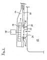
- FIG. 2 is a partial sectional view of a second embodiment of the cooking appliance according to the invention shown.
- the second embodiment differs from the first embodiment according to FIG. 1 through an additional air supply channel 30.
- the air supply channel 30 extends below the blow-out region 14.
- the air supply channel 30 extends substantially parallel to the blow-out region 14.
- the flow directions in the air supply channel 30 and in the blow-out region 14 are opposite.
- the air supply passage 30 is provided for sucking air, wherein the air usually at room temperature.
- the entrance of the air supply channel 30 is located on the outside of the housing of the cooking appliance.
- the air supply passage 30 has the same function as the air supply openings 28 in the embodiment according to FIG. 1 ,
- FIG. 3 is a partial sectional view of a third embodiment of the cooking appliance according to the invention shown.
- the third embodiment differs from the second embodiment essentially by the blower 36, which is designed as a tangential blower. Due to the shape of the tangential blower 36, the discharge channel is correspondingly higher in the third embodiment.
- FIG. 4 is a perspective view of a cut half diverter of the first embodiment of the cooking appliance according to the invention shown.
- FIG. 4 illustrates in particular the geometric properties of the diversion channel.
- the diversion channel is arranged above the cooking chamber 10, not shown.
- the first suction section 24 is located immediately above an opening in the upper wall of the cooking chamber 10.
- the second suction section 26 is located immediately above the perforated plate 20.
- the radial fan 16 is provided, which is not shown in this figure.
- the radial blower 16 subdivides the interior of the diversion channel into the intake region 12 and the blow-out region 14, the intake region being composed of the first intake section 24 and the second intake section 26.
- the height of the blow-off region 14 decreases along the flow direction.
- the width of the blow-out area decreases 14 along the flow direction.
- the outlet 34 of the blow-out area 14 is formed as a horizontal longitudinal slot.
- the output 34 is arranged above the feed opening of the cooking chamber.
- FIG. 5 shows a representation of a first embodiment of a separator 20 of the cooking appliance according to the invention.
- FIG. 5a shows a plan view
- FIG. 5b a side view
- FIG. 5c a sectional view
- FIG. 5d a perspective view of the first embodiment of the separator 20.
- the separator 20 has three round through holes 22.
- the separator 20 is made of metal.
- the separating device 20 is a curved round disk, which is essentially rotationally symmetrical.
- FIG. 6 an illustration of a second embodiment of the separator 20 of the cooking appliance according to the invention is shown.
- 6a shows a plan view
- FIG. 6b a perspective view of the second embodiment of the separator 20.
- the second embodiment of the separator 20 is formed as a flat, round surface piece and has in the central region also three round through holes 22.
- the cooking appliance according to the invention is characterized in that the suction region 12 is subdivided by the separating device 20 into a first intake section 24 with a higher temperature and into a second intake section 26 with a lower temperature.
- the catalyst arranged in the first intake section 24 is exposed to an ideal operating temperature.
- the second intake section 26 downstream blower 16, however, is not exposed to high temperature.
Landscapes
- Engineering & Computer Science (AREA)
- Chemical & Material Sciences (AREA)
- Combustion & Propulsion (AREA)
- Mechanical Engineering (AREA)
- General Engineering & Computer Science (AREA)
- Baking, Grill, Roasting (AREA)
Claims (19)
- Appareil de cuisson aveca) une enceinte de cuisson (10),b) au moins une soufflerie (16),c) une zone d'aspiration (12) couplée à l'enceinte de cuisson (10) et montée en amont d'au moins une soufflerie précitée (16), etd) une zone de soufflage (14) montée en aval d'au moins une soufflerie précité (16), oùe) la zone d'aspiration (12) est séparée au moyen d'une installation de séparation (20) en un premier tronçon d'aspiration (24) et un deuxième tronçon d'aspiration (26),f) le premier tronçon d'aspiration (24) et le deuxième tronçon d'aspiration (26) relativement à la direction d'écoulement, sont disposés l'un derrière l'autre, et le premier tronçon d'aspiration (24) se trouve directement au-dessus d'une ouverture dans le côté supérieur de l'enceinte de cuisson (10),caractérisé en ce que l'installation de séparation (20) présente pluralité de trous traversants (22), le premier tronçon d'aspiration (24) est réalisé d'une manière conique et s'élargit le long de la direction d'écoulement, et l'appareil de cuisson présente une installation d'amenée d'air (28 ; 30) pour l'aspiration d'air froid, qui est couplée à la zone d'aspiration 12) ou à une autre zone d'aspiration, où l'autre zone d'aspiration est couplée au côté d'aspiration d'au moins une soufflerie précitée (16) de sorte que par l'installation de séparation (20) et l'installation d'amenée d'air (28 ; 30), les températures dans le deuxième tronçon d'aspiration (26) sont plus basses que dans le premier tronçon d'aspiration (24).
- Appareil de cuisson selon la revendication 1, caractérisé en ce que l'installation de séparation (20) présente au moins une plaque à trous.
- Appareil de cuisson selon la revendication 1 ou 2, caractérisé en ce que la zone d'aspiration (12) et la zone de soufflage (14) forment un canal d'évacuation, qui est prévu de préférence comme canal d'air d'extraction et/ou qui est prévu pour l'évacuation de vapeurs de cuisson.
- Appareil de cuisson selon l'une des revendications précédentes, caractérisé en ce que la grandeur et/ou le nombre des trous traversants (22) est réglable manuellement et/ou automatiquement.
- Appareil de cuisson selon l'une des revendications précédentes, caractérisé en ce que le nombre de tours ou le débit de convoyage d'au moins une soufflerie précitée (16) est réglable manuellement et/ou automatiquement.
- Appareil de cuisson selon l'une des revendications précédentes, caractérisé en ce que la grandeur et/ou le nombre des trous traversants (22) est réglable en fonction du nombre de tours ou du débit de convoyage d'au moins une soufflerie précitée (16).
- Appareil de cuisson selon l'une des revendications précédentes, caractérisé en ce que l'installation d'amenée d'air (28 ; 30) présente au moins une ouverture d'amenée d'air (28).
- Appareil de cuisson selon l'une des revendications précédentes, caractérisé en ce que l'installation d'amenée d'air (28 ; 30) présente au moins un canal d'amenée d'air (30).
- Appareil de cuisson selon la revendication 8, caractérisé en ce qu'au moins un canal d'amenée d'air précité (30) s'étend d'une manière sensiblement horizontale.
- Appareil de cuisson selon l'une des revendications précédentes, caractérisé en ce que la zone de soufflage (14) s'étend d'une manière sensiblement horizontale.
- Appareil de cuisson selon l'une des revendications précédentes, caractérisé en ce que l'appareil de cuisson présente un catalyseur (32).
- Appareil de cuisson selon la revendication 11, caractérisé en ce que le catalyseur (32) est disposé dans le premier tronçon d'aspiration (12).
- Appareil de cuisson selon l'une des revendications précédentes, caractérisé en ce que la face en section transversale totale des trous traversants (22) représente entre 0,05% et 10%, en particulier entre 0,1% et 6%, de préférence entre 0,3% et 6% de la face en section transversale de la zone d'aspiration (12) dans la zone de l'installation de séparation (20).
- Appareil de cuisson selon l'une des revendications précédentes, caractérisé en ce que le rapport des flux volumiques ou massiques de l'écoulement de gaz aspiré de l'enceinte de cuisson à l'écoulement de gaz soufflé de la zone de soufflage est réglé ou peut être réglé entre 0,05% et 10%, en particulier entre 0,1% et 6%, de préférence entre 0,3% et 6%.
- Appareil de cuisson selon l'une des revendications 1 à 14, caractérisé en ce qu'au moins une soufflerie précitée (16) est réalisée comme soufflerie radiale.
- Appareil de cuisson selon l'une des revendications 1 à 14, caractérisé en ce qu'au moins une soufflerie précitée (16) est réalisée comme soufflerie tangentielle.
- Appareil de cuisson selon l'une des revendications précédentes, caractérisé en ce que le volume du deuxième tronçon d'aspiration (26) correspond au moins à environ la moitié du volume de la zone d'aspiration (14) entre l'enceinte de cuisson (10) et au moins une soufflerie précitée (16).
- Appareil de cuisson selon l'une des revendications précédentes, caractérisé en ce qu'au moins une partie des trous traversants (22) sont disposés dans la zone centrale de l'installation de séparation (20), ou bien les trous traversants (22) ont disposés exclusivement dans la zone centrale de l'installation de séparation (20), en particulier dans la plaque à trous (20).
- Appareil de cuisson selon l'une des revendications précédentes, caractérisé en ce que la grandeur et/ou le nombre des trous traversants sont ou est réglable au moyen de deux plaques à trous adjacentes, qui sont déplaçables ou tournantes l'une relativement à l'autre et/ou qui, par un recouvrement ou une superposition variable de leurs trous, libèrent des trous ou sections transversales de trous différents.
Priority Applications (1)
| Application Number | Priority Date | Filing Date | Title |
|---|---|---|---|
| EP14001679.1A EP2818800B1 (fr) | 2005-01-28 | 2005-11-23 | Appareil de cuisson |
Applications Claiming Priority (1)
| Application Number | Priority Date | Filing Date | Title |
|---|---|---|---|
| DE102005003975A DE102005003975A1 (de) | 2005-01-28 | 2005-01-28 | Gargerät |
Related Child Applications (1)
| Application Number | Title | Priority Date | Filing Date |
|---|---|---|---|
| EP14001679.1A Division EP2818800B1 (fr) | 2005-01-28 | 2005-11-23 | Appareil de cuisson |
Publications (3)
| Publication Number | Publication Date |
|---|---|
| EP1686322A2 EP1686322A2 (fr) | 2006-08-02 |
| EP1686322A3 EP1686322A3 (fr) | 2011-06-08 |
| EP1686322B1 true EP1686322B1 (fr) | 2014-05-14 |
Family
ID=36354081
Family Applications (2)
| Application Number | Title | Priority Date | Filing Date |
|---|---|---|---|
| EP14001679.1A Expired - Lifetime EP2818800B1 (fr) | 2005-01-28 | 2005-11-23 | Appareil de cuisson |
| EP05025516.5A Expired - Lifetime EP1686322B1 (fr) | 2005-01-28 | 2005-11-23 | Appareil de cuisson |
Family Applications Before (1)
| Application Number | Title | Priority Date | Filing Date |
|---|---|---|---|
| EP14001679.1A Expired - Lifetime EP2818800B1 (fr) | 2005-01-28 | 2005-11-23 | Appareil de cuisson |
Country Status (3)
| Country | Link |
|---|---|
| EP (2) | EP2818800B1 (fr) |
| DE (1) | DE102005003975A1 (fr) |
| ES (1) | ES2487141T3 (fr) |
Families Citing this family (6)
| Publication number | Priority date | Publication date | Assignee | Title |
|---|---|---|---|---|
| DE102006039130A1 (de) * | 2006-08-21 | 2008-02-28 | BSH Bosch und Siemens Hausgeräte GmbH | Gargerätevorrichtung |
| EP1855058B1 (fr) * | 2006-08-24 | 2017-04-19 | V-Zug AG | Procédé et appareil de cuisson de plats à la vapeur |
| ITTO20130849A1 (it) | 2013-10-18 | 2015-04-19 | Indesit Co Spa | Apparecchio di cottura domestico |
| DE102014203531A1 (de) * | 2014-02-27 | 2015-08-27 | BSH Hausgeräte GmbH | Gargerät mit einer spezifischen Kühlung einer Beleuchtungsvorrichtung |
| DE102017220234A1 (de) | 2017-11-14 | 2019-05-16 | BSH Hausgeräte GmbH | Gargerät mit spezifischer Wrasenabführvorrichtung |
| DE102021209455A1 (de) | 2021-08-27 | 2023-03-02 | BSH Hausgeräte GmbH | Verschlussvorrichtung sowie Gargerät mit Verschlussvorrichtung |
Family Cites Families (11)
| Publication number | Priority date | Publication date | Assignee | Title |
|---|---|---|---|---|
| DE2657267A1 (de) * | 1976-12-17 | 1978-06-22 | British Gas Corp | Ofen mit zwangsumlauf |
| DE3516847C3 (de) * | 1985-05-10 | 1995-02-23 | Miele & Cie | Elektroherd mit Katalysator |
| DE3741975A1 (de) * | 1987-12-11 | 1989-06-22 | Buderus Kuechentechnik | Vorrichtung zur steuerung eines mit dampf betriebenen gargeraetes und vorrichtung zum betreiben eines solchen geraetes |
| BE1005701A3 (nl) * | 1991-02-11 | 1993-12-21 | Atag Plan 3 B V | Heteluchtoven. |
| FR2688297B1 (fr) * | 1992-03-03 | 1999-07-30 | Europ Equip Menager | Appareil de cuisson electromenager, notamment fours ou cuisinieres comportant un dispositif de mise en depression. |
| DE4238660C2 (de) * | 1992-11-16 | 1994-09-01 | Bosch Siemens Hausgeraete | Backofen, insbesondere mit einer Einrichtung für pyrolytische Selbstreinigung |
| SE503682C2 (sv) * | 1994-11-17 | 1996-07-29 | Sveba Dahlen Ab | Anordning för ångalstring i ugnar |
| DE19638665A1 (de) * | 1996-09-20 | 1998-03-26 | Bosch Siemens Hausgeraete | Backofen mit einem Katalysator |
| DE19831087A1 (de) * | 1998-07-10 | 2000-01-13 | Bsh Bosch Siemens Hausgeraete | Backofen mit Luftleitblech |
| DE29821158U1 (de) * | 1998-11-26 | 2000-03-30 | AEG Hausgeräte GmbH, 90429 Nürnberg | Garofen mit Kühlung und Wrasenabführung |
| DE102004003409A1 (de) * | 2004-01-23 | 2005-08-18 | Electrolux Schwanden Ag | Multivalent nutzbares Belüftungs-/Kühlungsmodul für Gargeräte mit verschiedenen Garbetriebsarten |
-
2005
- 2005-01-28 DE DE102005003975A patent/DE102005003975A1/de not_active Withdrawn
- 2005-11-23 EP EP14001679.1A patent/EP2818800B1/fr not_active Expired - Lifetime
- 2005-11-23 EP EP05025516.5A patent/EP1686322B1/fr not_active Expired - Lifetime
- 2005-11-23 ES ES05025516.5T patent/ES2487141T3/es not_active Expired - Lifetime
Also Published As
| Publication number | Publication date |
|---|---|
| EP2818800B1 (fr) | 2017-06-07 |
| EP2818800A1 (fr) | 2014-12-31 |
| DE102005003975A1 (de) | 2006-08-03 |
| EP1686322A3 (fr) | 2011-06-08 |
| ES2487141T3 (es) | 2014-08-20 |
| EP1686322A2 (fr) | 2006-08-02 |
Similar Documents
| Publication | Publication Date | Title |
|---|---|---|
| EP3953645B1 (fr) | Dispositif pour faire chauffer un aliment à cuire | |
| EP3347651B1 (fr) | Hotte aspirante pour un appareil de cuisson, ainsi qu'appareil de cuisson équipé d'une hotte aspirante de ce type | |
| DE102017121367B4 (de) | Dunstabzug zum Abzug von auf einem Kochfeld erzeugter Abluft in vertikal unterhalb einer Kochfeldebene weisender Richtung | |
| EP1194721B1 (fr) | Dispositif d'aspiration d'air pour poste de travail | |
| EP3827204B1 (fr) | Système de table de cuisson | |
| DE102007015273A1 (de) | Mehrfachbackofen | |
| EP3701192A1 (fr) | Appareil combiné comprenant un dispositif d'aspiration des fumées et une table de cuisson | |
| DE2323596A1 (de) | Verfahren zur filterung von fetthaltigen daempfen und filtereinsatz fuer wrasenabzug | |
| WO2017029134A1 (fr) | Appareil combiné comprenant une plaque de cuisson et un dispositif d'aspiration des émanations | |
| EP1050718B1 (fr) | Four avec dispositif de d'extraction de la buée et d'adjonction d'air frais | |
| EP1686322B1 (fr) | Appareil de cuisson | |
| EP1004826A2 (fr) | Four avec dispositif de refroidissement et d'extraction de la buée | |
| DE3120569A1 (de) | "kuechendunstabzugshaube" | |
| EP3620721B1 (fr) | Dispositif d'aspiration de cuves de l'air extrait sur une plaque de cuisson | |
| EP2857758B1 (fr) | Dispositif d'aspiration de vapeur | |
| DE102017216456A1 (de) | Lüftungsvorrichtung für Kochfeld und Kochfeld mit Lüftungsvorrichtung | |
| EP2031309A2 (fr) | Dispositif et procédé destinés à l'alimentation et l'évacuation d'air d'un four de cuisson | |
| DE202015104361U1 (de) | Dunstabzugshaube für ein Gargerät sowie Gargerät mit einer solchen Dunstabzugshaube | |
| DE2758348C2 (de) | Belüftungsvorrichtung für einen Abzugschrank von Labortischen | |
| WO2009062809A2 (fr) | Dispositif d'aspiration de vapeurs | |
| EP0322735A2 (fr) | Four de boulangerie avec un dispositif d'extraction de la buée | |
| EP0942235A1 (fr) | Feu de boulanger avec boíte d'aspiration | |
| EP3807576B1 (fr) | Appareil de cuisson | |
| EP1014002B1 (fr) | Cuisinière, en particulier cuisinière électrique | |
| DE102005034303B4 (de) | Garofen |
Legal Events
| Date | Code | Title | Description |
|---|---|---|---|
| PUAI | Public reference made under article 153(3) epc to a published international application that has entered the european phase |
Free format text: ORIGINAL CODE: 0009012 |
|
| AK | Designated contracting states |
Kind code of ref document: A2 Designated state(s): AT BE BG CH CY CZ DE DK EE ES FI FR GB GR HU IE IS IT LI LT LU LV MC NL PL PT RO SE SI SK TR |
|
| AX | Request for extension of the european patent |
Extension state: AL BA HR MK YU |
|
| RAP1 | Party data changed (applicant data changed or rights of an application transferred) |
Owner name: ELECTROLUX HOME PRODUCTS CORPORATION N.V. |
|
| PUAL | Search report despatched |
Free format text: ORIGINAL CODE: 0009013 |
|
| AK | Designated contracting states |
Kind code of ref document: A3 Designated state(s): AT BE BG CH CY CZ DE DK EE ES FI FR GB GR HU IE IS IT LI LT LU LV MC NL PL PT RO SE SI SK TR |
|
| AX | Request for extension of the european patent |
Extension state: AL BA HR MK YU |
|
| RAP1 | Party data changed (applicant data changed or rights of an application transferred) |
Owner name: ELECTROLUX HOME PRODUCTS CORPORATION N.V. |
|
| 17P | Request for examination filed |
Effective date: 20110622 |
|
| AKX | Designation fees paid |
Designated state(s): AT BE BG CH CY CZ DE DK EE ES FI FR GB GR HU IE IS IT LI LT LU LV MC NL PL PT RO SE SI SK TR |
|
| 17Q | First examination report despatched |
Effective date: 20130131 |
|
| GRAP | Despatch of communication of intention to grant a patent |
Free format text: ORIGINAL CODE: EPIDOSNIGR1 |
|
| INTG | Intention to grant announced |
Effective date: 20140102 |
|
| GRAS | Grant fee paid |
Free format text: ORIGINAL CODE: EPIDOSNIGR3 |
|
| GRAA | (expected) grant |
Free format text: ORIGINAL CODE: 0009210 |
|
| AK | Designated contracting states |
Kind code of ref document: B1 Designated state(s): AT BE BG CH CY CZ DE DK EE ES FI FR GB GR HU IE IS IT LI LT LU LV MC NL PL PT RO SE SI SK TR |
|
| REG | Reference to a national code |
Ref country code: GB Ref legal event code: FG4D Free format text: NOT ENGLISH |
|
| REG | Reference to a national code |
Ref country code: AT Ref legal event code: REF Ref document number: 668582 Country of ref document: AT Kind code of ref document: T Effective date: 20140615 |
|
| REG | Reference to a national code |
Ref country code: IE Ref legal event code: FG4D Free format text: LANGUAGE OF EP DOCUMENT: GERMAN Ref country code: DE Ref legal event code: R096 Ref document number: 502005014350 Country of ref document: DE Effective date: 20140618 |
|
| REG | Reference to a national code |
Ref country code: ES Ref legal event code: FG2A Ref document number: 2487141 Country of ref document: ES Kind code of ref document: T3 Effective date: 20140820 |
|
| REG | Reference to a national code |
Ref country code: NL Ref legal event code: VDEP Effective date: 20140514 |
|
| REG | Reference to a national code |
Ref country code: LT Ref legal event code: MG4D |
|
| PG25 | Lapsed in a contracting state [announced via postgrant information from national office to epo] |
Ref country code: FI Free format text: LAPSE BECAUSE OF FAILURE TO SUBMIT A TRANSLATION OF THE DESCRIPTION OR TO PAY THE FEE WITHIN THE PRESCRIBED TIME-LIMIT Effective date: 20140514 Ref country code: CY Free format text: LAPSE BECAUSE OF FAILURE TO SUBMIT A TRANSLATION OF THE DESCRIPTION OR TO PAY THE FEE WITHIN THE PRESCRIBED TIME-LIMIT Effective date: 20140514 Ref country code: IS Free format text: LAPSE BECAUSE OF FAILURE TO SUBMIT A TRANSLATION OF THE DESCRIPTION OR TO PAY THE FEE WITHIN THE PRESCRIBED TIME-LIMIT Effective date: 20140914 Ref country code: GR Free format text: LAPSE BECAUSE OF FAILURE TO SUBMIT A TRANSLATION OF THE DESCRIPTION OR TO PAY THE FEE WITHIN THE PRESCRIBED TIME-LIMIT Effective date: 20140815 Ref country code: LT Free format text: LAPSE BECAUSE OF FAILURE TO SUBMIT A TRANSLATION OF THE DESCRIPTION OR TO PAY THE FEE WITHIN THE PRESCRIBED TIME-LIMIT Effective date: 20140514 |
|
| PG25 | Lapsed in a contracting state [announced via postgrant information from national office to epo] |
Ref country code: LV Free format text: LAPSE BECAUSE OF FAILURE TO SUBMIT A TRANSLATION OF THE DESCRIPTION OR TO PAY THE FEE WITHIN THE PRESCRIBED TIME-LIMIT Effective date: 20140514 Ref country code: SE Free format text: LAPSE BECAUSE OF FAILURE TO SUBMIT A TRANSLATION OF THE DESCRIPTION OR TO PAY THE FEE WITHIN THE PRESCRIBED TIME-LIMIT Effective date: 20140514 Ref country code: PL Free format text: LAPSE BECAUSE OF FAILURE TO SUBMIT A TRANSLATION OF THE DESCRIPTION OR TO PAY THE FEE WITHIN THE PRESCRIBED TIME-LIMIT Effective date: 20140514 |
|
| PG25 | Lapsed in a contracting state [announced via postgrant information from national office to epo] |
Ref country code: PT Free format text: LAPSE BECAUSE OF FAILURE TO SUBMIT A TRANSLATION OF THE DESCRIPTION OR TO PAY THE FEE WITHIN THE PRESCRIBED TIME-LIMIT Effective date: 20140915 |
|
| PG25 | Lapsed in a contracting state [announced via postgrant information from national office to epo] |
Ref country code: DK Free format text: LAPSE BECAUSE OF FAILURE TO SUBMIT A TRANSLATION OF THE DESCRIPTION OR TO PAY THE FEE WITHIN THE PRESCRIBED TIME-LIMIT Effective date: 20140514 Ref country code: SK Free format text: LAPSE BECAUSE OF FAILURE TO SUBMIT A TRANSLATION OF THE DESCRIPTION OR TO PAY THE FEE WITHIN THE PRESCRIBED TIME-LIMIT Effective date: 20140514 Ref country code: EE Free format text: LAPSE BECAUSE OF FAILURE TO SUBMIT A TRANSLATION OF THE DESCRIPTION OR TO PAY THE FEE WITHIN THE PRESCRIBED TIME-LIMIT Effective date: 20140514 Ref country code: CZ Free format text: LAPSE BECAUSE OF FAILURE TO SUBMIT A TRANSLATION OF THE DESCRIPTION OR TO PAY THE FEE WITHIN THE PRESCRIBED TIME-LIMIT Effective date: 20140514 Ref country code: RO Free format text: LAPSE BECAUSE OF FAILURE TO SUBMIT A TRANSLATION OF THE DESCRIPTION OR TO PAY THE FEE WITHIN THE PRESCRIBED TIME-LIMIT Effective date: 20140514 |
|
| PGFP | Annual fee paid to national office [announced via postgrant information from national office to epo] |
Ref country code: ES Payment date: 20141126 Year of fee payment: 10 Ref country code: CH Payment date: 20141119 Year of fee payment: 10 Ref country code: GB Payment date: 20141119 Year of fee payment: 10 Ref country code: DE Payment date: 20141119 Year of fee payment: 10 Ref country code: FR Payment date: 20141119 Year of fee payment: 10 |
|
| REG | Reference to a national code |
Ref country code: DE Ref legal event code: R097 Ref document number: 502005014350 Country of ref document: DE |
|
| PG25 | Lapsed in a contracting state [announced via postgrant information from national office to epo] |
Ref country code: NL Free format text: LAPSE BECAUSE OF FAILURE TO SUBMIT A TRANSLATION OF THE DESCRIPTION OR TO PAY THE FEE WITHIN THE PRESCRIBED TIME-LIMIT Effective date: 20140514 |
|
| PLBE | No opposition filed within time limit |
Free format text: ORIGINAL CODE: 0009261 |
|
| STAA | Information on the status of an ep patent application or granted ep patent |
Free format text: STATUS: NO OPPOSITION FILED WITHIN TIME LIMIT |
|
| PGFP | Annual fee paid to national office [announced via postgrant information from national office to epo] |
Ref country code: IT Payment date: 20141126 Year of fee payment: 10 |
|
| 26N | No opposition filed |
Effective date: 20150217 |
|
| REG | Reference to a national code |
Ref country code: DE Ref legal event code: R097 Ref document number: 502005014350 Country of ref document: DE Effective date: 20150217 |
|
| PG25 | Lapsed in a contracting state [announced via postgrant information from national office to epo] |
Ref country code: MC Free format text: LAPSE BECAUSE OF FAILURE TO SUBMIT A TRANSLATION OF THE DESCRIPTION OR TO PAY THE FEE WITHIN THE PRESCRIBED TIME-LIMIT Effective date: 20140514 Ref country code: LU Free format text: LAPSE BECAUSE OF FAILURE TO SUBMIT A TRANSLATION OF THE DESCRIPTION OR TO PAY THE FEE WITHIN THE PRESCRIBED TIME-LIMIT Effective date: 20141123 Ref country code: BE Free format text: LAPSE BECAUSE OF NON-PAYMENT OF DUE FEES Effective date: 20141130 |
|
| PG25 | Lapsed in a contracting state [announced via postgrant information from national office to epo] |
Ref country code: SI Free format text: LAPSE BECAUSE OF FAILURE TO SUBMIT A TRANSLATION OF THE DESCRIPTION OR TO PAY THE FEE WITHIN THE PRESCRIBED TIME-LIMIT Effective date: 20140514 |
|
| REG | Reference to a national code |
Ref country code: IE Ref legal event code: MM4A |
|
| PG25 | Lapsed in a contracting state [announced via postgrant information from national office to epo] |
Ref country code: IE Free format text: LAPSE BECAUSE OF NON-PAYMENT OF DUE FEES Effective date: 20141123 |
|
| REG | Reference to a national code |
Ref country code: AT Ref legal event code: MM01 Ref document number: 668582 Country of ref document: AT Kind code of ref document: T Effective date: 20141123 |
|
| PG25 | Lapsed in a contracting state [announced via postgrant information from national office to epo] |
Ref country code: AT Free format text: LAPSE BECAUSE OF NON-PAYMENT OF DUE FEES Effective date: 20141123 |
|
| PG25 | Lapsed in a contracting state [announced via postgrant information from national office to epo] |
Ref country code: BG Free format text: LAPSE BECAUSE OF FAILURE TO SUBMIT A TRANSLATION OF THE DESCRIPTION OR TO PAY THE FEE WITHIN THE PRESCRIBED TIME-LIMIT Effective date: 20140514 |
|
| REG | Reference to a national code |
Ref country code: DE Ref legal event code: R119 Ref document number: 502005014350 Country of ref document: DE |
|
| REG | Reference to a national code |
Ref country code: CH Ref legal event code: PL |
|
| GBPC | Gb: european patent ceased through non-payment of renewal fee |
Effective date: 20151123 |
|
| PG25 | Lapsed in a contracting state [announced via postgrant information from national office to epo] |
Ref country code: IT Free format text: LAPSE BECAUSE OF NON-PAYMENT OF DUE FEES Effective date: 20151123 Ref country code: HU Free format text: LAPSE BECAUSE OF FAILURE TO SUBMIT A TRANSLATION OF THE DESCRIPTION OR TO PAY THE FEE WITHIN THE PRESCRIBED TIME-LIMIT; INVALID AB INITIO Effective date: 20051123 Ref country code: LI Free format text: LAPSE BECAUSE OF NON-PAYMENT OF DUE FEES Effective date: 20151130 Ref country code: CH Free format text: LAPSE BECAUSE OF NON-PAYMENT OF DUE FEES Effective date: 20151130 |
|
| REG | Reference to a national code |
Ref country code: FR Ref legal event code: ST Effective date: 20160729 |
|
| PG25 | Lapsed in a contracting state [announced via postgrant information from national office to epo] |
Ref country code: GB Free format text: LAPSE BECAUSE OF NON-PAYMENT OF DUE FEES Effective date: 20151123 Ref country code: DE Free format text: LAPSE BECAUSE OF NON-PAYMENT OF DUE FEES Effective date: 20160601 |
|
| PG25 | Lapsed in a contracting state [announced via postgrant information from national office to epo] |
Ref country code: FR Free format text: LAPSE BECAUSE OF NON-PAYMENT OF DUE FEES Effective date: 20151130 |
|
| REG | Reference to a national code |
Ref country code: ES Ref legal event code: FD2A Effective date: 20161229 |
|
| PG25 | Lapsed in a contracting state [announced via postgrant information from national office to epo] |
Ref country code: ES Free format text: LAPSE BECAUSE OF NON-PAYMENT OF DUE FEES Effective date: 20151124 |
|
| PG25 | Lapsed in a contracting state [announced via postgrant information from national office to epo] |
Ref country code: TR Free format text: LAPSE BECAUSE OF NON-PAYMENT OF DUE FEES Effective date: 20151123 |