EP1688657B1 - Rohrleitungsverschlussvorrichtung - Google Patents
Rohrleitungsverschlussvorrichtung Download PDFInfo
- Publication number
- EP1688657B1 EP1688657B1 EP04792951A EP04792951A EP1688657B1 EP 1688657 B1 EP1688657 B1 EP 1688657B1 EP 04792951 A EP04792951 A EP 04792951A EP 04792951 A EP04792951 A EP 04792951A EP 1688657 B1 EP1688657 B1 EP 1688657B1
- Authority
- EP
- European Patent Office
- Prior art keywords
- diameter
- control shaft
- pressing plate
- engaging
- annular member
- Prior art date
- Legal status (The legal status is an assumption and is not a legal conclusion. Google has not performed a legal analysis and makes no representation as to the accuracy of the status listed.)
- Expired - Lifetime
Links
- 230000002093 peripheral effect Effects 0.000 claims abstract description 53
- 238000011144 upstream manufacturing Methods 0.000 claims abstract description 32
- 239000012530 fluid Substances 0.000 claims description 17
- 230000002265 prevention Effects 0.000 abstract 5
- 230000000149 penetrating effect Effects 0.000 abstract 2
- XLYOFNOQVPJJNP-UHFFFAOYSA-N water Substances O XLYOFNOQVPJJNP-UHFFFAOYSA-N 0.000 description 41
- 238000010276 construction Methods 0.000 description 18
- 230000006835 compression Effects 0.000 description 6
- 238000007906 compression Methods 0.000 description 6
- 238000000034 method Methods 0.000 description 6
- 239000008399 tap water Substances 0.000 description 3
- 235000020679 tap water Nutrition 0.000 description 3
- 229920006311 Urethane elastomer Polymers 0.000 description 2
- 230000000903 blocking effect Effects 0.000 description 2
- 230000002950 deficient Effects 0.000 description 1
- 229920001971 elastomer Polymers 0.000 description 1
- 230000007257 malfunction Effects 0.000 description 1
- 230000000717 retained effect Effects 0.000 description 1
- 238000007789 sealing Methods 0.000 description 1
- 230000035939 shock Effects 0.000 description 1
Images




Classifications
-
- F—MECHANICAL ENGINEERING; LIGHTING; HEATING; WEAPONS; BLASTING
- F16—ENGINEERING ELEMENTS AND UNITS; GENERAL MEASURES FOR PRODUCING AND MAINTAINING EFFECTIVE FUNCTIONING OF MACHINES OR INSTALLATIONS; THERMAL INSULATION IN GENERAL
- F16L—PIPES; JOINTS OR FITTINGS FOR PIPES; SUPPORTS FOR PIPES, CABLES OR PROTECTIVE TUBING; MEANS FOR THERMAL INSULATION IN GENERAL
- F16L55/00—Devices or appurtenances for use in, or in connection with, pipes or pipe systems
- F16L55/10—Means for stopping flow in pipes or hoses
- F16L55/1018—Pivoting closing devices
-
- F—MECHANICAL ENGINEERING; LIGHTING; HEATING; WEAPONS; BLASTING
- F16—ENGINEERING ELEMENTS AND UNITS; GENERAL MEASURES FOR PRODUCING AND MAINTAINING EFFECTIVE FUNCTIONING OF MACHINES OR INSTALLATIONS; THERMAL INSULATION IN GENERAL
- F16L—PIPES; JOINTS OR FITTINGS FOR PIPES; SUPPORTS FOR PIPES, CABLES OR PROTECTIVE TUBING; MEANS FOR THERMAL INSULATION IN GENERAL
- F16L55/00—Devices or appurtenances for use in, or in connection with, pipes or pipe systems
- F16L55/10—Means for stopping flow in pipes or hoses
- F16L55/12—Means for stopping flow in pipes or hoses by introducing into the pipe a member expandable in situ
Definitions
- the present invention relates to a pipeline closing apparatus used in changing of a sluice valve or a butterfly valve disposed in a branch pipe for a fireplug or an air valve diverging from and connected to a water main while water supply is continued in the water main with water leakage from the branch pipe being prevented.
- the invention refers to a pipeline closing apparatus with the features in the preamble of claim 1.
- a conventional pipeline closing apparatus includes a bottomed tubular lid member 7 attachable to a downstream end portion of a sluice valve for closing an end opening of a branch pipe diverging from and connected to a fluid transmitting main and having the sluice valve disposed in an intermediate portion thereof, a cylindrical first control shaft 8 extending through the lid member 7 to be axially slidable in sealed condition, and a second control shaft 9 extending through the first control shaft 8 to be axially slidable.
- the first control shaft 8 and second control shaft 9 have pressing plates 10 and 11 attached to inward end regions thereof, respectively.
- An elastic annular member 12 having a circular cross section is disposed between the pressing plates 10 and 11 to be elastically deformable, by being clamped and pressed by the pair of pressing plates 10 and 11 from axial directions, to a diameterincreased position in tight contact with an inner peripheral surface of the branch pipe to block between the inner peripheral surface and outer peripheral portions of the two pressing plates 10 and 11.
- a retaining device D is provided as having engaging link pairs 13 and 14 arranged in three circumferential positions and extending between the inward end of the second control shaft 9 and the first pressing plate 10 disposed upstream, for flexing and bulging to a diameter-increased position to engage a large diameter pipe portion formed upstream of a blocked position by the elastic annular member 12, in response to an outward sliding movement of the second control shaft 9 relative to the first control shaft 8.
- the retaining device D includes a mounting tubular member 21 slidably fitted on the inward end portion of the second control shaft 9 and having second connecting elements 22 provided in three circumferential positions on an outer peripheral surface thereof to which to ends of the upstream engaging links 13 pivotably connected. Ends of the downstream engaging links 14 are pivotably connected to first connecting elements 20 provided in three circumferential positions on an end surface of the upstream second pressing plate 11. Further, a stopper nut 15 and a lock nut 16 are screwed to the inward end portion of the second control shaft 9 for determining a maximum upstream movement position of the second pressing plate 11 relative to the second control shaft 9 (see Patent Documents 1 and 2, for example).
- JP 7081669 B2 discloses a pipeline closing apparatus comprising a lid member attachable to a downstream end portion of a sluice valve or an end portion of a pipe portion connected thereto for closing an end opening of a branch pipe connected to and diverging from a fluid transmitting main and having the sluice valve disposed therein; a cylindrical first control shaft extending through the lid member to be axially slidable in sealed condition; a second control shaft extending through the first control shaft to be axially slidable; a first pressing plate attached to an inward end region of the first control shaft; a second pressing plate attached to an inward end region of the second control shaft upstream of the first pressing plate; an elastic annular member disposed between the first pressing plate and the second pressing plate and elastically deformable to a diameter-increased position for tight contact with an inner peripheral surface of the branch pipe by being clamped and pressed between both of the pressing plates from axial directions; thereby to block between the inner peripheral surface and outer peripheral portions of the pressing plates
- a security device for blocking ducts in order to prevent unauthorized access to the duct.
- This security device includes members expandable radially to engage walls of the duct by a drive so that the device is firmly retained in the duct and a reversal is prevented.
- a space is formed between the engaging link pairs 13 and 14 and the outer peripheral surface of the second control shaft 9, when the engaging link pairs 13 and 14 are stretched to a diameter-reduced position, for allowing a flexion to the extent that flexing pivotal connecting points S2 of the engaging link pairs 13 and 14 project toward the second control shaft 9 beyond lines extending between pivotal connecting points S1 to the second connecting elements 22 of the mounting tubular member 21 and pivotal connecting points S3 to the first connecting elements 20 of the second pressing plate 11.
- the engaging link pairs 13 and 14 may flex to a reverse condition in which the flexing pivotal connecting points S2 of the engaging link pairs 13 and 14 project toward the second control shaft 9 beyond the lines extending between pivotal connecting points S1 to the second connecting elements 22 of the mounting tubular member 21 and pivotal connecting points S3 to the first connecting elements 20 of the second pressing plate 11.
- Such a reverse condition of the engaging link pairs 13 and 14 will result in the loss of the desired engaging function of the engaging link pairs 13 and 14.
- the present invention has been made having regard to the state of the art noted above, and its primary object is to provide a pipeline closing apparatus capable of performing a desired engaging function of engaging link pairs reliably and effectively at all times even when any components of a retaining device become loose or are set in error.
- the invention is characterized by the features of claim 1.
- the engaging link pairs can perform the desired engaging function reliably and effectively at all times even when any control components for controlling the retaining device become loose, or any set up errors are produced, or any excessive clattering occurs with the pivotal connecting points of the engaging link pairs.
- the characteristic feature of the pipeline closing apparatus lies in that the reversal preventing device includes a ring shaped elastic correcting member for contacting one of the engaging links when the engaging link pairs stretched to the diameter-reduced position reach the predetermined outwardly bent position, the ring shaped elastic correcting member being mounted on a mounting tubular member fitted on the inward end region of the second control shaft and having a connecting element pivotably connected to an end portion of one of the engaging links.
- one of the engaging links pivotably connected to the connecting element of the mounting tubular member contacts the ring shaped elastic correcting member mounted on the mounting tubular member fitted on the inward end region of the second control shaft before the flexing pivotal connecting points of the engaging link pairs reach the lines extending between the opposite pivotal connecting points when the engaging link pairs in the diameter increased position are stretched to the diameter-reduced position, thereby to reliably maintain the link pairs in the predetermined outwardly bent position.
- the ring shaped elastic correcting member is simply mounted on the mounting tubular member for pivotably connecting one of the engaging links thereto, which can eliminate the need for securing a large space for providing the ring-shaped elastic correcting member to simplify the overall construction and facilitate an assembling operation as well as absorbing shocks and reducing noise in time of contact with the links.
- a second characteristic feature of the pipeline closing apparatus according to the present invention lies in that the elastic annular member is shaped cylindrical and has an axially middle portion larger in diameter than axially opposite end portions.
- the cylindrical elastic annular member disposed between the pair of pressing, plates is elastically deformed to a diameter-increased position by being clamped and pressed by these pressing plates from axial directions, the operational resistance at the time of compression is reduced by an amount corresponding to the reduced diameter at the axially opposite end portions of the elastic annular member.
- the axially middle portion of the elastic annular member is larger in diameter than the axially opposite end portions, which can secure an amount of deformation to increase the diameter as the entire elastic annular member.
- a third characteristic feature of the pipeline closing apparatus according to the present invention lies in that the axially middle portion of the elastic annular member has an outer peripheral surface which is shaped partly spherical to project most outwardly at an axial middle part thereof.
- the axially opposite end portions of the elastic annular member are smaller in diameter and the outer peripheral surface of the axially middle portion of the elastic annular member is shaped partly spherical to project most outwardly at the axially middle part thereof when the cylindrical elastic annular member disposed between the pair of pressing plates is elastically deformed to the diameter-increased position by being clamped and pressed by the pressing plates from axial directions, the operational resistance at the time of compression is reduced.
- the axially middle portion of the elastic annular member is larger in diameter than the axially opposite end portions, which can secure an amount of deformation to increase the diameter as the entire elastic annular member.
- a fourth tharacteristic feature of the pipeline closing apparatus according to the present invention lies in that both of the pressing plates include annular holding portions to be in contact with outer circumferential surfaces of the axially opposite end portions of the cylindrical elastic annular member.
- the annular holding portions formed on both of the pressing plates bite into a bulging portion of the elastic annular member bulging radially outwardly when the cylindrical elastic annular member disposed between the pressing plates is elastically deformed to the diameter increased position by being clamped and pressed by the pressing plates from axial directions.
- the elastic annular member is reliably prevented from being dislocated by fluid pressure.
- a fifth characteristic feature of the pipeline closing apparatus lies in that the large diameter middle portion of the elastic annular member has an inner peripheral surface that is shaped partly spherical to project most outwardly at an axially middle part thereof.
- the operational resistance at the time of compression can be significantly reduced when the cylindrical elastic annular member disposed between the pressing plates is elastically deformed to the diameter increased position by being clamped and pressed by the pressing plates from axial directions.
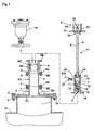
- the pipeline closing apparatus A is used when changing a sluice valve 6 disposed on a branch pipe P2 for a new sluice valve 6 while water supply is continued through a water main P1 and yet water leakage from the branch pipe P2 is prevented.
- Fig. 1 illustrates a branch pipe connecting construction provided in an intermediate position along a fluid transmitting line.
- a diverging pipe portion 1 projects from, and is formed integrally with, a midway position of the water main P1 which is an example of fluid transmitting mains.
- the diverging pipe portion 1 includes a connecting flange 1A to which a connecting lid member 2 with a connecting pipe portion 2A having a diameter smaller than the inside diameter of the connecting flange 1A is detachably and fixedly connected in sealed condition by bolts 3 and nuts 4.
- a connecting flange 2B is formed on the connecting pipe portion 2A of the connecting lid member 2.
- a diverging pipe 5 having connecting flanges 5A and 5B provided at opposite ends thereof and a sluice valve 6 having connecting flanges 6A and 6B provided at opposite ends thereof are detachably and fixedly connected to the connecting flange 2B in sealed condition by bolts 3 and nuts 4, respectively.
- the branch pipe P2 is constituted by the diverging pipe portion 1 of the water main P1, the connecting lid member 2, the diverging pipe 5 and the sluice valve 6.
- An implement such as an air valve VA or a fireplug, or a water pipe or the like is detachably and fixedly connected in sealed condition to the downstream connecting flange 6B of the sluice valve 6.
- the side of the branch pipe P2 adjacent the water main P1 is called upstream side.
- a bottomed tubular lid member 7 is connected in sealed condition to the downstream connecting flange 6B of the sluice valve 6 to close an end opening of the branch pipe P2.
- the bottomed tubular lid member 7 includes a connecting flange 7A to be connected in sealed condition to the downstream connecting flange 6B, and a bottom wall portion 7B having a cylindrical first control shaft 8 extending through a central portion of the bottom wall portion 7B to be axially slidable in sealed condition and a second control shaft 9 extending through the first control shaft 8 to be axially slidable.
- the first control shaft 8 and second control shaft 9 have, provided at inward end regions thereof, a closing device C for blocking (shutting off) the fluid passage of the branch pipe P2, i.e. the fluid passage in the connecting pipe portion 2A of the connecting lid member 2, and a retaining device D including engaging link pairs 13 and 14 flexing and bulging in a diameter-increased position for engaging a large diameter tubular wall portion upstream of the position blocked by the closing device C, i.e. a circumferential edge of a passage opening of a lid plate portion 2C of the connecting lid member 2.
- a control device E is provided for the first control shaft 8 and second control shaft 9 to control the closing device C and retaining device D from outside through both of the control shafts 8 and 9.
- the first control shaft 8 has a first pressing plate 10 fixedly fitted on the inward end thereof.
- the first pressing plate 10 includes an annular pressing surface 10A, and a hollow portion 10B opening in a coaxial circle toward a distal end.
- the second control shaft 9 has a second pressing plate 11 axially slidably fitted on the inward end region thereof.
- the second pressing plate 11 includes an annular pressing surface 11A axially opposed to the pressing face 10A of the first pressing plate 10, and a tubular portion 11B axially slidable into the hollow portion 10B of the first pressing plate 10.
- a stopper nut 15 and a lock nut 16 are screwed to a threaded shaft portion 9a formed on the inward end region of the second control shaft 9 to determine a maximum upstream movement position of the second pressing plate 11 relative to the second control shaft 9.
- the sides of the first control shaft 8 and second control shaft 9 adjacent the water main P1 are referred to as the inward end sides of the first control shaft 8 and second control shaft 9, respectively.
- the outside diameters of the first pressing plate 10 and second pressing plate 11 are smaller than an inside diameter of the connecting pipe portion 2A of the connecting lid member 2 constituting part of the branch pipe P2 so that the plates in an accommodating chamber 7C of the lid member 7 may be advanced into and retracted from the connecting pipe portion 2A of the connecting lid member 2 through the sluice valve 6 and the diverging pipe 5.
- the outer diameters of the first pressing plate 10 and second pressing plate 11 are smaller than an inside diameter of a fluid passage 6D through a ball valve member 6C of the sluice valve 6 which the smallest inside diameter among those of all the components of the branch pipe P2.
- an elastic annular member 12 made of urethane rubber is fitted on the tubular portion 11B of the second pressing plate 11.
- the elastic annular member 12 has an outside diameter smaller than the inside diameter of the fluid passage 6D through the ball valve member 6C of the sluice valve 6 in a non-pressurized condition (natural condition), and is elastically deformable to a diameter-increased position in tight contact with an inner peripheral wall surface of the connecting pipe portion 2A of the connecting lid member 2 by being axially clamped and pressed between both of the pressing surfaces 10A and 11A of the pressing plates 10 and 11, thereby to block between the inner peripheral wall surface and outer peripheral portions of the pressing plates 10 and 11.
- the elastic annular member 12 has a cylindrical shape to be mounted tight on the tubular portion 11B of the second pressing plate 11, and has an axially middle portion 12a that is larger in diameter than axially opposite end portions 12b.
- the large diameter middle portion 12a has an outer peripheral surface 12d which is shaped partly spherical to protrude most outwardly at an axially middle part thereof.
- each of the small diameter opposite end portions 12b has an outer peripheral end surface portion 12c at an end surface thereof shaped as an annular inclined surface that is inclined by a predetermined angle (30 degrees in the present embodiment) relative to a vertical plane perpendicular to the axis.
- the pressing surface 10A of the first pressing plate 10 includes an outer peripheral end surface portion 10a while the pressing surface 11A of the second pressing plate 11 includes an outer peripheral end surface portion 11a, respectively.
- Each of the outer peripheral end surface portions 10a and 11a is formed as an annular inclined pressing surface having the further radially outward portion located the closer to the axially middle position of the elastic annular member 12, so as to make tight contact axially with the outer peripheral end surface portion 12c of each of the opposite end surfaces of the elastic annular member 12.
- annular holding portions 10C and 11C are formed in an outer circumferential edge side of the pressing surface 10A of the first pressing plate 10 and an outer circumferential edge side of the pressing surface 11A of the second pressing plate 11 to be in contact with and fitted on outer circumferential surfaces of the axially opposite end portions 12b of the elastic annular member 12.
- Each of the axially opposite end portions 12b of the elastic annular member 12 has a small diameter and the outer peripheral surface 12d of the axially middle portion 12a is shaped partly spherical to protrude most outwardly at the axially middle part thereof.
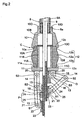
- the upstream engaging links 13 and downstream engaging links 14 constitute the engaging link pairs.
- First plate-like connecting elements 20 are fixed to three circumferential positions of an upstream end surface of the second pressing plate 11. Ends of the downstream engaging links 14 are pivotably connected to the first connecting elements 20.
- Second plate-like connecting elements 22 are fixed to three circumferential positions at outer peripheries of a mounting tubular member 21 slidably fitted on the threaded shaft portion 9a formed on the inward end region of the second control shaft 9. Ends of the upstream engaging links 13 are pivotably connected to the second connecting elements 22.
- a stopper nut 23 is screwed to a distal end of the inward threaded shaft portion 9a of the second control shaft 9 to determine a maximum upstream movement position of the mounting tubular member 21.
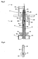
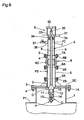
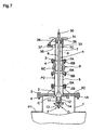
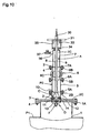
- the engaging link pairs 13 and 14 are pivotably connected between the three pairs of the first and second connecting elements 20 and 22 axially opposed to each other, respectively, of the first connecting elements 20 of the second pressing plate 11 and the second connecting elements 22 of the mounting tubular member 21 As shown in Figs. 7 through 9 , the engaging link pairs 13 and 14 are flexed to bulge to the diameter-increased position for engaging the inner peripheral wall located upstream of the blocked portion closed by the elastic annular member 12, i.e. the circumferential edges of the passage opening of the lid plate portion 2C of the connecting lid member 2, in response to a sliding movement of the second control shaft 9 toward the outer end thereof relative to the first control shaft 8. As shown in Fig.
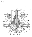
- a reversal preventing device F which, when the engaging link pairs 13 and 14 of the retaining device D are stretched to a diameter-reduced position, contacts and limits the engaging link pairs 13 and 14 to an outwardly bent position with flexing pivotal portions S2 of the engaging link pairs 13 and 14 protruding radially outward. More particularly, in the outwardly bent position, the flexing pivotal connecting points S2 of the engaging link pairs 13 and 14 are positioned to protrude radially outward beyond lines Y extending between pivotal connecting points S1 to the second connecting elements 22 of the mounting tubular member 21 and pivotal connecting points S3 to the first connecting elements 20 of the second pressing plate 11.
- the reversal preventing device F includes a tubular elastic correcting member 24 acting as an elastic limiting element for first contacting the engaging links 13 stretched to the diameter-reduced position, and a correcting flange 25 of the mounting tubular member 21 acting as a rigid limiting element for contacting the engaging links 13 having contacted the tubular elastic correcting member 24.
- the tubular elastic correcting member 24 made of rubber is fitted on the inward threaded shaft portion 9a of the second control shaft 9 between the mounting tubular member 21 and the lock nut 16 to be elastically deformable to contact sides of the three upstream engaging links 13 being stretched to the diameter-reduced position.
- the correcting flange 25 is formed integrally with a downstream end of the mounting tubular member 21 to contact the sides of the three upstream engaging links 13 stretching and oscillating radially inward while locally elastically compressing the tubular elastic correcting member 24, thereby to receive the upstream engaging links 13 in the outwardly bent position defining a predetermined limit at a minimum distance to the lines Y.
- the first control shaft 8 includes an elongated control body tubular shaft SA having a mounting shaft portion 8a at an inward end side thereof fixedly fitted to a mounting tubular portion 10D of the first pressing plate 10 from the axial direction, and a control extension tubular shaft 8B fixedly fitted on an outward end side of the control body tubular shaft 8A.
- the control extension tubular shaft 8B has an inner peripheral surface 8b formed as an equilateral hexagonal inner peripheral surface with different diameters.
- the second control shaft 9 includes an elongated control body shaft 9A having the inward end threaded shaft portion 9a, and a control extension shaft 9B fixedly screwed to an outward end portion of the control body shaft 9A.
- the control extension shaft 9B has an outward end threaded shaft portion 9b on which a control screw member 30 is screwed to contact an end portion of the control extension tubular shaft 8B of the first control shaft 8 through a thrust bearing 29, and a large diameter angular shaft portion 9c with an equilateral hexagonal outer peripheral surface fitted on the control extension tubular shaft 8B of the first control shaft 8 to be unrotatable relative thereto and slidable only in the axial direction.
- a pair of first presser control rods 31 are detachably fitted on and held by the control extension tubular shaft 8B of the first control shaft 8.
- Each of the first presser control rods 31 includes a first engaging ring 33 engageable with and disengageable from a second presser control rod 32 detachably fitted on and held by the control extension shaft 9B of the second control shaft 9 to prevent, in the engaged position, the second control shaft 9 from sliding outward relative to the first control shaft 8 against the water pressure, and a second engaging ring 35 engageable with and disengageable from one of a pair of L-shaped engageable pieces 34 fixed to the bottom wall portion 7B of the lid member 7 to prevent, in the engaged position, the first control shaft 8 from sliding outward relative to the lid member 7 against the water pressure.
- the lid member 7 has a drain pipe 36 connected thereto for confirming a water stoppage.
- the drain pipe 36 has a tap 37 with a switch lever 37A.
- the pair of second engaging rings 35 are removed from the engageable pieces 34 of the lid member 7, with the pair of first engaging rings 33 remaining engaged with the second presser control rod 32.
- Both of the control shafts 8 and 9 are pulled up from the lid member 7 to place the closing device C and retaining device D in the accommodating chamber 7C of the lid member 7.
- the sluice valve 6 is opened, and the two control shafts 8 and 9 are pushed down relative to the lid member 7.
- the pair of second engaging rings 35 are engaged with the engageable pieces 34 of the lid member 7 to maintain the control shafts 8 and 9 in a push-in position.
- the retaining device D is positioned within the diverging pipe portion 1 having a larger sectional area than the fluid passage in the connecting pipe portion 2A of the connecting lid member 2.
- the switch lever 37A of the tap 37 connected to the drain pipe 36 of the lid member 7 is opened to discharge water.
- the sluice valve 6 is removed from the connecting flange 5B of the diverging pipe 5. Then, a new sluice valve 6 is attached to the connecting flange 5B of the diverging pipe 5.
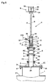
- the first pressing plate 10 is moved toward the second pressing plate 11 by a manual tightening operation of the control screw member 30.
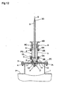
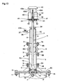
- the first pressing plate 10 may be moved toward the second pressing plate 11 by a pair of hydraulic jacks 40.
- first presser control rods 31 are detachably fitted on and held by the control extension tubular shaft 8B of the first control shaft 8.
- a mounting plate 41 for the hydraulic jack 40 is attached to each of the first presser control rods 31 through bolts 42.
- the control extension shaft 9B of the second control shaft 9 has a generally T-shaped control arm 43 detachably screwed thereto and defining a pressure-receiving surface 43a for contacting extreme ends of piston rods 40A of the hydraulic jacks 40.
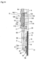
- Fig. 14 shows an improvement in the reversal preventing device F which, when the engaging link pairs 13 and 14 of the retaining device D are stretched to the diameter-reduced position, contacts and limits the engaging link pairs 13 and 14 to the outwardly bent position with the flexing pivotal portions S2 of the engaging link pairs 13 and 14 protruding radially outward.
- the correcting flange 25 is formed integrally with the downstream end of a metallic mounting tubular member 21 to contact the sides of the three upstream engaging links 13 stretching and oscillating radially inward, thereby to receive the upstream engaging links 13 in the outwardly bent position defining the predetermined limit at a minimum distance to the lines Y.
- a ring shaped elastic correcting member 45 made of urethane rubber or the like is fitted between the correcting flange 25 and the second connecting elements 22, which is elastically deformable by contacting the sides of the three upstream engaging links 13 being stretched to the diameter-reduced position.
- the reversal preventing device F in the third embodiment also includes, as in the first embodiment, the ring shaped elastic correcting member 45 acting as the elastic limiting portion for first contacting the engaging links 13 stretched to the diameter-reduced position, and the correcting flange 25 of the mounting tubular member 21 acting as the rigid limiting portion for contacting the engaging links 13 having contacted the elastic correcting ring 45.
- the other aspects of the construction are the same as those described in the first embodiment. Thus, like reference numerals are affixed to like components, and are not described.
- Figs. 15 and 16 show another form of the elastic annular member 12 noted above.
- This elastic annular member 12 is shaped cylindrical to be detachably and tightly mounted on the tubular portion 11B of the second pressing plate 11, and has the axial middle portion 12a larger in diameter than the axially opposite end portions 12b.
- the large diameter middle portion 12a has the outer peripheral surface 12d shaped partly spherical to protrude most outwardly at the axially middle part thereof.
- the large diameter middle portion 12a of the elastic annular member 12 has an inner peripheral surface 12e shaped partly spherical to protrude most outwardly at the axially middle part thereof.
- Each of the small diameter opposite end portions 12b has the outer peripheral end surface portion 12c at the end surface thereof shaped as the annular inclined surface that is inclined by the predetermined angle (30 degrees in the present embodiment) relative to the vertical plane perpendicular to the axis.
- Each of the axially opposite end portions 12b of the elastic annular member 12 has a small diameter, and each of the outer peripheral surface 12d and inner peripheral surface 12e of the large diameter middle portion 12a is shaped partly spherical to protrude most outwardly at the axially middle part thereof.
- Figs. 17 and 18 show a further form of the elastic annual member 12 noted above.
- This elastic annular member 12 is shaped cylindrical to be detachably and tightly mounted on the tubular portion 11B of the second pressing plate 11, and has the axially middle portion 12a larger in diameter than the axially opposite end portions 12b.
- the large diameter middle portion 12a has the outer peripheral surface 12d formed as a circumferential surface having a diameter equal to or substantially the same as the diameter of the annular holding portions 10C and 11C of the pressing plates 10 and 11 over the entire axial range thereof.
- each of the small diameter opposite end portions 12b has the outer peripheral end surface portion 12c at the end surface thereof formed as the annular inclined surface inclined by the predetermined angle (30 degrees in the present embodiment) relative to the vertical plane perpendicular to the axis.
- the other aspects of the construction are the same as those described in the first embodiment. Thus, like reference numerals are affixed to like components, and are not described.
- the above embodiments have been described as using the pipeline closing apparatus A in the method of changing the sluice valve 6 disposed in the branch pipe of the water pipe.
- the pipeline closing apparatus A may be used also in a method of changing other valves or connecting pipes than the sluice valve.
- a further embodiment will be described hereinafter with reference to the drawings, in which the pipeline closing apparatus A is used in a method of changing a butterfly valve V connected to a diverging pipe portion 52 integrally formed with and projecting from an intermediate portion along a water pipe 51. It should be noted that the construction of the pipeline closing apparatus A is the same as in the foregoing embodiments and its explanation is omitted accordingly.
- Fig. 19 shows a pipe connecting construction used when a need has arisen for changing a butterfly valve V due to a malfunction or defective operation while maintaining a flow of water supply in the water pipe 51.
- an upstream connecting flange 55A of a switch valve 55 for working is detachably and fixedly connected in sealed condition by bolts 56 or the like to a downstream connecting flange 60B of the butterfly valve V.
- the switch valve 55 includes a valve member 55C slidable and openable along a direction perpendicular to an axis of divergence Y to an extent of fully or substantially fully opening a fluid passage in a valve casing 60.
- a drill unit B includes a connecting flange 70A detachably and fixedly connected to a downstream connecting flange 55B of the working switch valve 55 by a plurality of bolts 56 and nuts 57 representing fastening elements.
- An upstream connecting flange 60A of the butterfly valve V is connected to a downstream connecting flange 54B of a connecting pipe 54.
- the connecting pipe 54 includes an upstream connecting flange 54A connected to a connecting flange 52A of the diverging pipe portion 52.
- the drill unit B is driven by a prime mover such as an electric motor, an engine or the like to apply a driving rotational force and a feeding force to a drive rotary shaft 71 supported by a casing 70 to be rotatable and slidable along the axis of divergence Y. Then, a hole saw 73 fixedly connected to a connecting flange 72 provided at an extreme end of the drive rotary shaft 71 is advanced through the fluid passage in the working switch valve 55, thereby to cut off and remove the butterfly valve V together with the valve member 61 while maintaining the flow of the fluid in the water pipe 51.
- a prime mover such as an electric motor, an engine or the like
- a gap L between a cutting tip 73a of a cylindrical body 73A and a distal end of a center drill 73B is set so that the cutting tip 73a of the cylindrical body 73A may cut a downstream opening of a partly spherical inner peripheral wall surface 60a of the valve casing 60 after a relative movement in a diametrical direction between the two elements 73B and 61 is restricted with progress of cutting and removal of the valve member 61 by the center drill 73B.
- the drive rotary shaft 71 of the drill unit B is moved backward to return the hole saw 73 into an accommodating space of the casing 70.
- the valve member 55C of the working switch valve 55 is closed, and then the connecting flange 70A of the drill unit B is removed from the downstream connecting flange 55B of the working switch valve 55 to remove the drill unit B together with the cut valve member 61.
- the connecting flange 7A of the lid member 7 of the pipeline closing apparatus A is detachably and fixedly connected in sealed condition by bolts 56 and nuts 57 to the downstream connecting flange 55B of the working switch valve 55, for closing and sealing the fluid passage upstream of a position where the butterfly valve V is mounted through a fluid passage W in the butterfly valve V having the valve member 61 and valve stems 62A and 62B cut and removed in part by the hole saw 73.
- Fig. 20 shows a condition where the engaging link pairs 13 and 14 mounted on the pipeline closing apparatus A and flexed to the diameter-increased position are engaged with an inner peripheral wall surface, i.e. a circumferential edge of a diverging opening in the inner peripheral surface, of the water pipe 51 located upstream of the position blocked by the elastic annular member 12.
- the first control shaft 8 is slidingly pushed inward relative to the second control shaft 9 to move the first pressing plate 10 toward the second pressing plate 11, thereby to clamp and press the elastic annular member 12 in the diameter-reduced condition.
- the elastic annular member 12 is elastically deformed to the diameter-increased position in tight contact with the inner peripheral wall surface of the diverging pipe portion 52, thereby to block and seal between the inner peripheral wall surface of the diverging pipe portion 52 and the outer peripheries of the pressing plates 10 and 11.
- a drain tap 37 provided for the lid member 7 is opened to discharge water.
- the control device E, lid member 7, working switch valve 55, butterfly valve V and connecting pipe 54 are removed successively.
- the reversal preventing device F comprises the combination of the tubular elastic correcting member 24 mounted on the inward end of the second control shaft 9 and the correcting flange 25 of the mounting tubular member 21, or the combination of the ring shaped elastic correcting member 45 and the correcting flange 25 of the mounting tubular member 21.
- the reversal preventing device F may be formed of either one of them.
- the reversal preventing device F comprises the tubular elastic correcting member 24 mounted on the inward end of the second control shaft 9 and the correcting flange 25 of the mounting tubular member 21, or the ring shaped elastic correcting member 45 and the correcting flange 25 of the mounting tubular member 21.
- a limiting member or members may be provided between the engaging link pairs 13 and 14 for contacting and limiting the link pairs to the predetermined outwardly bent position where the flexing pivotal connecting points of the engaging link pairs 13 and 14 protrude radially outward when the engaging link pairs 13 and 14 of the retaining device D are stretched to the diameter-reduced position.
- any constructions acting as the reversal preventing device F may be used as long as they can contact and limit the link pairs 13 and 14 to the predetermined outwardly bent position where the flexing pivotal portions S2 of the engaging link pairs 13 and 14 are positioned to protrude radially outward beyond the lines Y extending between the pivotal connecting points S1 to the second connecting elements 22 of the mounting tubular member 21 and the pivotal connecting points S3 to the first connecting elements 20 of the second pressing plate 11.
- the engaging link pairs 13 and 14 of the retaining device D are engageable with the pipe wall portion upstream of the position blocked by the elastic annular member 12, i.e. the circumferential edge of the passage opening of the lid plate portion 2C of the connecting lid member 2.
- the engaging link pairs 13 and 14 may be engageable with the circumferential opening edge of the diverging pipe portion 1 of the water main P1.
- the diverging pipe portion 1 formed integrally with the water main 1 which is one example of fluid transmitting mains.
- the invention is not limited to this construction.
- a plurality of divided joint members may be detachably and fixedly connected to a water main as arranged circumferentially thereof, and a pipe joint may be attached to one of the joint members, which pipe joint has, projecting integrally therefrom a diverging pipe portion for communicating from a radial direction of the pipe (a direction along an axis of divergence) with a through bore formed in a peripheral wall of the water main.
- tubular elastic correcting member 24 and the correcting flange 25 of the mounting tubular member 21 constituting the reversal preventing device F are made to contact the engaging links 13, but may be made to contact the other links 14 or both of the links 13 and 14.
- the pipeline closing apparatus may be used in a valve changing method for carrying out changing of a valve such as a sluice valve, a butterfly valve or other connecting pipe connected to a branch pipe or the like connected to and diverging from a water pipe or the like while maintaining a water supply through the water pipe.
- a valve such as a sluice valve, a butterfly valve or other connecting pipe connected to a branch pipe or the like connected to and diverging from a water pipe or the like while maintaining a water supply through the water pipe.
Landscapes
- Engineering & Computer Science (AREA)
- General Engineering & Computer Science (AREA)
- Mechanical Engineering (AREA)
- Pipe Accessories (AREA)
Claims (5)
- Rohrleitungsverschlussvorrichtung umfassend:ein Deckelelement (7), das auf einen ablaufseitigen Endbereich eines Ventils (6) oder auf einen Endbereich eines Rohrteils anschließbar ist, um eine endständige Öffnung einer Rohrabzweigung (P2) zu verschließen, wobei die Rohrabzweigung mit einer fluidführenden Hauptleitung (P1) verbunden ist und von dieser abzweigt, und das Ventil (6) aufweist;eine erste zylindrische Steuerstange (8), die sich durch das Deckelelement erstreckt und unter abgedichteten Bedingungen axial verschiebbar ist;eine zweite Steuerstange (9), die sich innerhalb der ersten Steuerstange erstreckt und axial verschiebbar ist;eine erste Pressplatte (10), die an dem inneren Endbereich der ersten Steuerstange (8) angeordnet ist;eine zweite Pressplatte (11), die an dem inneren Endbereich der zweiten Steuerstange (9) oberhalb der ersten Pressplatte (10) angeordnet ist;ein elastisches ringförmiges Element (12), das zwischen der ersten Pressplatte (10) und der zweiten Pressplatte (11) angeordnet und elastisch verformbar zu einem größeren Durchmesser ist, um dichten Kontakt mit einer inneren Umfangsoberfläche der Rohrabzweigung (P2) herzustellen, durch Einspannen und Zusammenpressen zwischen den beiden Pressplatten (10, 11) in axialer Richtung, um dadurch den Bereich zwischen der inneren Umfangsfläche und den äußeren peripheren Bereichen der Pressplatten (10, 11) zu versperren; undein Halteelement (D) zwischen dem inneren Endbereich der zweiten Steuerstange (9) und der zweiten Pressplatte (11), und mit einem Paar in Eingriff bringbarer Hebelarme (13, 14), die sich verschwenken und aufweiten zu einem größeren Durchmesser, um stromaufwärts der von dem elastischen ringförmigen Element (12) versperrten Position in Eingriff zu gelangen, in Reaktion auf das nach außen Verschieben der zweiten Steuerstange (9) relativ zu der ersten Steuerstange (8);wobei ein Rückzug-Verhinderungselement (F) angeordnet ist, welches, wenn die in Eingriff bringbaren Hebelarme (13, 14) des Halteelements (D) auf einen reduzierten Durchmesser gestreckt sind, die in Eingriff bringbaren Hebelarme (13, 14) kontaktiert und in eine nach außen geschwenkte Position bringt, in der die Schwenklager (S2) der in Eingriff bringbaren Hebelarme (13, 14) radial nach außen zeigen,dadurch gekennzeichnet, dassdas Rückzug-Verhinderungselement (F) ein ringförmiges elastisches Korrekturelement (45) enthält, um mit einem der in Eingriff bringbaren Hebelarme (13, 14) in Anlage zu kommen, wenn die Hebelarme (13, 14) auf ihren reduzierten Durchmesser ausgestreckt sind, die dann die vorbestimmte nach außen geschwenkte Position erreichen können, wobei das ringförmige elastische Korrekturelement (45) auf einem rohrförmigen Befestigungselement (21) montiert ist, das seinerseits an dem inneren Endbereich der zweiten Steuerstange (9) angeordnet ist und ein Verbindungselement (22)aufweist, das schwenkbar mit dem Endbereich einer der Hebelarme (13, 14) verbunden ist.
- Rohrleitungsverschlussvorrichtung nach Anspruch 1,
dadurch gekennzeichnet,
dass das elastische ringförmige Element (12) zylindrisch geformt ist und einen axialen Mittelbereich (12a) aufweist, der einen größeren Durchmesser besitzt, als die axial entgegengesetzten Endbereiche (12b). - Rohrleitungsverschlussvorrichtung nach Anspruch 2,
dadurch gekennzeichnet,
dass der axiale Mittelbereich (12a) des elastischen ringförmigen Elements (12) eine äußere Umlauffläche (12d) aufweist, die teilweise sphärisch geformt ist, und in einem axial mittleren Bereich am stärksten hervorsteht. - Rohrleitungsverschlussvorrichtung nach Anspruch 1,
dadurch gekennzeichnet,
dass beide Pressplatten (10, 11) ringförmige Halterungsbereiche (10c, 11c) besitzen, um im Kontakt mit äußeren umlaufenden Flächen der axial gegenüberliegenden Endbereiche (12b) des elastischen ringförmigen Elements (12) in Zylinderform zu sein. - Rohrleitungsverschlussvorrichtung nach Anspruch 3,
dadurch gekennzeichnet,
dass der Mittelbereich (12a) des elastischen ringförmigen Elements (12) mit dem größeren Durchmesser eine innere periphere Oberfläche aufweist, die teilweise sphärisch geformt ist, um in einem axial mittleren Bereich am stärksten nach außen zu ragen.
Applications Claiming Priority (3)
| Application Number | Priority Date | Filing Date | Title |
|---|---|---|---|
| JP2003372409A JP3664719B2 (ja) | 2003-10-31 | 2003-10-31 | 枝管流路遮蔽装置 |
| JP2004116811A JP4594641B2 (ja) | 2004-04-12 | 2004-04-12 | 流体配管系の弁交換工法 |
| PCT/JP2004/015823 WO2005043027A1 (ja) | 2003-10-31 | 2004-10-26 | 管路閉塞装置 |
Publications (3)
| Publication Number | Publication Date |
|---|---|
| EP1688657A1 EP1688657A1 (de) | 2006-08-09 |
| EP1688657A4 EP1688657A4 (de) | 2010-11-24 |
| EP1688657B1 true EP1688657B1 (de) | 2012-06-20 |
Family
ID=34554765
Family Applications (1)
| Application Number | Title | Priority Date | Filing Date |
|---|---|---|---|
| EP04792951A Expired - Lifetime EP1688657B1 (de) | 2003-10-31 | 2004-10-26 | Rohrleitungsverschlussvorrichtung |
Country Status (3)
| Country | Link |
|---|---|
| US (1) | US7717136B2 (de) |
| EP (1) | EP1688657B1 (de) |
| WO (1) | WO2005043027A1 (de) |
Families Citing this family (10)
| Publication number | Priority date | Publication date | Assignee | Title |
|---|---|---|---|---|
| MX2013000573A (es) | 2010-07-15 | 2013-03-25 | Deep Sea Innovations Llc | Aparatos y metodos para cerrar y reabrir una tuberia. |
| US8826990B2 (en) | 2010-07-15 | 2014-09-09 | Deep Sea Innovations, Llc | Apparatuses and methods for closing and reopening a pipe |
| JP5639920B2 (ja) * | 2011-02-18 | 2014-12-10 | コスモ工機株式会社 | 接続部材の脱着方法 |
| US9377037B2 (en) | 2013-03-15 | 2016-06-28 | Ron R. Daniels | Lock device and method of use |
| RU2724286C1 (ru) * | 2019-05-17 | 2020-06-22 | Общество с ограниченной ответственностью "КЕМИГРИН" | Клапан запорный пневматический для герметизации дренажных систем и удержания разлива химических веществ |
| RU194781U1 (ru) * | 2019-05-20 | 2019-12-23 | Общество с ограниченной ответственностью "КЕМИГРИН" | Клапан запорный пневматический для герметизации дренажных систем и удержания разлива химических веществ |
| KR102600348B1 (ko) * | 2021-04-15 | 2023-11-08 | 정근석 | 외부에서 유체이송관 내부의 유체차단구를 열고 닫을 수 있도록 기능하는 부단수 장치 및 이를 이용하는 부단수 방법 |
| US12209379B2 (en) * | 2021-06-24 | 2025-01-28 | Clover Equipment, LLC | Anchored hole cover |
| US11525518B1 (en) * | 2021-08-17 | 2022-12-13 | Mueller International, Llc | Pipe stopper assembly |
| CN116538381B (zh) * | 2023-05-23 | 2026-04-14 | 广西民族大学 | 一种智能巡检机器人 |
Family Cites Families (16)
| Publication number | Priority date | Publication date | Assignee | Title |
|---|---|---|---|---|
| US2108068A (en) * | 1934-10-15 | 1938-02-15 | Larry Timothy Allan | Pressure control fitting |
| US2171939A (en) * | 1936-09-14 | 1939-09-05 | Mueller Co | Apparatus for fluid control |
| US2672161A (en) * | 1949-05-24 | 1954-03-16 | Brauer Morris | Apparatus for plugging holes in pipe lines |
| US2588188A (en) * | 1951-01-08 | 1952-03-04 | Weisman Sam | Backwater valve |
| US3275023A (en) * | 1964-02-17 | 1966-09-27 | Morris M Raspante | Temporary sealing means for conduit under pressure |
| US3473555A (en) * | 1967-08-15 | 1969-10-21 | Expando Seal Tool Inc | Fluid flow precluding tool |
| US3550636A (en) * | 1968-08-26 | 1970-12-29 | Willis H Hearne | Plastic ball,bolt and wing set |
| JPS62111735A (ja) | 1985-11-11 | 1987-05-22 | 三菱樹脂株式会社 | ポリエ−テルイミドフイルム |
| JPS62111735U (de) * | 1985-12-27 | 1987-07-16 | ||
| JPH0781669B2 (ja) | 1987-10-15 | 1995-09-06 | 矢野技研株式会社 | 対枝管作業方法および枝管遮閉装置 |
| JP2657925B2 (ja) | 1988-05-06 | 1997-09-30 | 六菱ゴム株式会社 | 管体耐圧閉塞機構 |
| JPH043196A (ja) | 1990-04-20 | 1992-01-08 | Matsushita Electric Ind Co Ltd | データ表示選択装置 |
| GB9304649D0 (en) * | 1993-03-08 | 1993-04-28 | Pioden Controls Ltd | Security device |
| JPH0781669A (ja) | 1993-09-16 | 1995-03-28 | Zeniraito V:Kk | 灯浮標の係留装置 |
| JPH10255369A (ja) | 1997-03-17 | 1998-09-25 | Sanyo Electric Co Ltd | ディスク記録再生装置 |
| JP7081669B2 (ja) * | 2018-08-03 | 2022-06-07 | 日本電気株式会社 | 情報処理装置、情報処理方法および情報処理プログラム |
-
2004
- 2004-10-26 EP EP04792951A patent/EP1688657B1/de not_active Expired - Lifetime
- 2004-10-26 US US10/577,787 patent/US7717136B2/en active Active
- 2004-10-26 WO PCT/JP2004/015823 patent/WO2005043027A1/ja not_active Ceased
Also Published As
| Publication number | Publication date |
|---|---|
| HK1097032A1 (zh) | 2007-06-15 |
| WO2005043027A1 (ja) | 2005-05-12 |
| EP1688657A1 (de) | 2006-08-09 |
| EP1688657A4 (de) | 2010-11-24 |
| US20080277930A1 (en) | 2008-11-13 |
| US7717136B2 (en) | 2010-05-18 |
Similar Documents
| Publication | Publication Date | Title |
|---|---|---|
| JP7370629B2 (ja) | 弁装置及び流体管路構造 | |
| JP4719209B2 (ja) | 流体配管系統の流路遮断方法 | |
| US7717136B2 (en) | Pipeline closing apparatus | |
| JP4318673B2 (ja) | 流体配管系の機器交換方法 | |
| CN100554753C (zh) | 管路封闭装置 | |
| JP7369853B2 (ja) | 制流弁の開弁方法及びそれに用いられる制流弁 | |
| EP3527863B1 (de) | Ventilvorrichtung | |
| EP1914456B1 (de) | Absperrschiebervorrichtung | |
| KR101554028B1 (ko) | 버터플라이 밸브 면간길이를 갖는 신축관 일체형 밸브 | |
| JPH0550629B2 (de) | ||
| JP3722612B2 (ja) | プラスチック製バタフライ弁 | |
| JP4594641B2 (ja) | 流体配管系の弁交換工法 | |
| JP4653571B2 (ja) | 流体配管系統の流路遮断方法及び管内流路遮断装置 | |
| JP3860804B2 (ja) | 孔閉塞冶具 | |
| HK1097032B (en) | Pipe line-closing device | |
| KR200338623Y1 (ko) | 더블 사이드 세그먼트 플러그형 메탈시트 볼밸브 | |
| JPH11148565A (ja) | ボールバルブ | |
| CN223938712U (zh) | 一种防回流的锻钢球阀阀门 | |
| JP4101223B2 (ja) | ブッシュ装着機及び枝管流路遮蔽装置 | |
| CN223424771U (zh) | 一种截止阀 | |
| CN223306345U (zh) | 一种偏心球阀的预紧结构 | |
| CN111120666A (zh) | 一种便于维护的新型气动膨胀蝶阀 | |
| GB2347196A (en) | Ball valve spindle sealing | |
| KR200273458Y1 (ko) | 볼밸브의 누수차단장치 | |
| KR200334647Y1 (ko) | 세그먼트 플러그형 메탈시트 볼밸브 |
Legal Events
| Date | Code | Title | Description |
|---|---|---|---|
| PUAI | Public reference made under article 153(3) epc to a published international application that has entered the european phase |
Free format text: ORIGINAL CODE: 0009012 |
|
| 17P | Request for examination filed |
Effective date: 20060511 |
|
| AK | Designated contracting states |
Kind code of ref document: A1 Designated state(s): DE FR GB IT |
|
| DAX | Request for extension of the european patent (deleted) | ||
| RBV | Designated contracting states (corrected) |
Designated state(s): DE FR GB IT |
|
| A4 | Supplementary search report drawn up and despatched |
Effective date: 20101027 |
|
| RIC1 | Information provided on ipc code assigned before grant |
Ipc: F16L 55/12 20060101ALI20101021BHEP Ipc: F16L 55/00 20060101AFI20050518BHEP Ipc: E03B 7/00 20060101ALI20101021BHEP Ipc: F16L 55/10 20060101ALI20101021BHEP |
|
| 17Q | First examination report despatched |
Effective date: 20110609 |
|
| GRAC | Information related to communication of intention to grant a patent modified |
Free format text: ORIGINAL CODE: EPIDOSCIGR1 |
|
| GRAP | Despatch of communication of intention to grant a patent |
Free format text: ORIGINAL CODE: EPIDOSNIGR1 |
|
| RIC1 | Information provided on ipc code assigned before grant |
Ipc: F16L 55/00 20060101AFI20111031BHEP Ipc: E03B 7/00 20060101ALI20111031BHEP Ipc: F16L 55/12 20060101ALI20111031BHEP Ipc: F16L 55/10 20060101ALI20111031BHEP |
|
| GRAS | Grant fee paid |
Free format text: ORIGINAL CODE: EPIDOSNIGR3 |
|
| RIN1 | Information on inventor provided before grant (corrected) |
Inventor name: SAKAI, ATSUSHI ,WATERWORKS TECH. DEV. ORG. CO, LTD |
|
| GRAA | (expected) grant |
Free format text: ORIGINAL CODE: 0009210 |
|
| RAP1 | Party data changed (applicant data changed or rights of an application transferred) |
Owner name: WATERWORKS TECHNOLOGY DEVELOPMENT ORGANIZATION CO. |
|
| AK | Designated contracting states |
Kind code of ref document: B1 Designated state(s): DE FR GB IT |
|
| REG | Reference to a national code |
Ref country code: GB Ref legal event code: FG4D |
|
| REG | Reference to a national code |
Ref country code: DE Ref legal event code: R096 Ref document number: 602004038316 Country of ref document: DE Effective date: 20120816 |
|
| PLBE | No opposition filed within time limit |
Free format text: ORIGINAL CODE: 0009261 |
|
| STAA | Information on the status of an ep patent application or granted ep patent |
Free format text: STATUS: NO OPPOSITION FILED WITHIN TIME LIMIT |
|
| 26N | No opposition filed |
Effective date: 20130321 |
|
| REG | Reference to a national code |
Ref country code: DE Ref legal event code: R097 Ref document number: 602004038316 Country of ref document: DE Effective date: 20130321 |
|
| REG | Reference to a national code |
Ref country code: FR Ref legal event code: PLFP Year of fee payment: 13 |
|
| REG | Reference to a national code |
Ref country code: FR Ref legal event code: PLFP Year of fee payment: 14 |
|
| REG | Reference to a national code |
Ref country code: FR Ref legal event code: PLFP Year of fee payment: 15 |
|
| P01 | Opt-out of the competence of the unified patent court (upc) registered |
Effective date: 20230418 |
|
| PGFP | Annual fee paid to national office [announced via postgrant information from national office to epo] |
Ref country code: GB Payment date: 20230929 Year of fee payment: 20 |
|
| PGFP | Annual fee paid to national office [announced via postgrant information from national office to epo] |
Ref country code: IT Payment date: 20230926 Year of fee payment: 20 Ref country code: FR Payment date: 20231023 Year of fee payment: 20 Ref country code: DE Payment date: 20230929 Year of fee payment: 20 |
|
| REG | Reference to a national code |
Ref country code: DE Ref legal event code: R071 Ref document number: 602004038316 Country of ref document: DE |
|
| REG | Reference to a national code |
Ref country code: GB Ref legal event code: PE20 Expiry date: 20241025 |
|
| PG25 | Lapsed in a contracting state [announced via postgrant information from national office to epo] |
Ref country code: GB Free format text: LAPSE BECAUSE OF EXPIRATION OF PROTECTION Effective date: 20241025 |
|
| PG25 | Lapsed in a contracting state [announced via postgrant information from national office to epo] |
Ref country code: GB Free format text: LAPSE BECAUSE OF EXPIRATION OF PROTECTION Effective date: 20241025 |