EP1689049B1 - Dispositif pour appliquer des manchons sur câbles électriques - Google Patents
Dispositif pour appliquer des manchons sur câbles électriques Download PDFInfo
- Publication number
- EP1689049B1 EP1689049B1 EP20060101224 EP06101224A EP1689049B1 EP 1689049 B1 EP1689049 B1 EP 1689049B1 EP 20060101224 EP20060101224 EP 20060101224 EP 06101224 A EP06101224 A EP 06101224A EP 1689049 B1 EP1689049 B1 EP 1689049B1
- Authority
- EP
- European Patent Office
- Prior art keywords
- module
- grommet
- housing
- grommets
- base module
- Prior art date
- Legal status (The legal status is an assumption and is not a legal conclusion. Google has not performed a legal analysis and makes no representation as to the accuracy of the status listed.)
- Expired - Lifetime
Links
Images



Classifications
-
- H—ELECTRICITY
- H01—ELECTRIC ELEMENTS
- H01R—ELECTRICALLY-CONDUCTIVE CONNECTIONS; STRUCTURAL ASSOCIATIONS OF A PLURALITY OF MUTUALLY-INSULATED ELECTRICAL CONNECTING ELEMENTS; COUPLING DEVICES; CURRENT COLLECTORS
- H01R43/00—Apparatus or processes specially adapted for manufacturing, assembling, maintaining, or repairing of line connectors or current collectors or for joining electric conductors
- H01R43/005—Apparatus or processes specially adapted for manufacturing, assembling, maintaining, or repairing of line connectors or current collectors or for joining electric conductors for making dustproof, splashproof, drip-proof, waterproof, or flameproof connection, coupling, or casing
-
- H—ELECTRICITY
- H01—ELECTRIC ELEMENTS
- H01R—ELECTRICALLY-CONDUCTIVE CONNECTIONS; STRUCTURAL ASSOCIATIONS OF A PLURALITY OF MUTUALLY-INSULATED ELECTRICAL CONNECTING ELEMENTS; COUPLING DEVICES; CURRENT COLLECTORS
- H01R13/00—Details of coupling devices of the kinds covered by groups H01R12/70 or H01R24/00 - H01R33/00
- H01R13/46—Bases; Cases
- H01R13/52—Dustproof, splashproof, drip-proof, waterproof, or flameproof cases
- H01R13/5205—Sealing means between cable and housing, e.g. grommet
-
- H—ELECTRICITY
- H01—ELECTRIC ELEMENTS
- H01R—ELECTRICALLY-CONDUCTIVE CONNECTIONS; STRUCTURAL ASSOCIATIONS OF A PLURALITY OF MUTUALLY-INSULATED ELECTRICAL CONNECTING ELEMENTS; COUPLING DEVICES; CURRENT COLLECTORS
- H01R43/00—Apparatus or processes specially adapted for manufacturing, assembling, maintaining, or repairing of line connectors or current collectors or for joining electric conductors
- H01R43/28—Apparatus or processes specially adapted for manufacturing, assembling, maintaining, or repairing of line connectors or current collectors or for joining electric conductors for wire processing before connecting to contact members, not provided for in groups H01R43/02 - H01R43/26
Definitions
- the invention relates to a device for Tüllenbe conferenceung of electrical cables consisting of a base module for supporting a Tüllenmoduls and a Be thoroughlyungsmoduls, the Tüllenmodul provides the mating spouts in the correct position the mounting module and the placement module, the cable equipped with the spouts.
- the device consists of an open at one end face, fillable with nozzles drum which is drivable about an axis extending obliquely to the horizontal axis. In the interior of the drum arranged blades pass a protruding into the drum conveyor rail with rotating drum grommets for the purpose of storage storage and further transport.
- An ejector with a movable up and down centering mandrel leads each of the first spout in the feed rail of a rotating device which has a plurality of mandrels and is incrementally rotatable by a certain angle, wherein in a first position of the rotating device in each case a spout on the Tip of a thorn is pushed. In a second position of the rotating device, the spout is pushed by means of a Aufschiebeaji for the purpose of expanding on a part of the mandrel. In a further position of the rotating device, the spout is removed from the mandrel by means of a placement head with Tüllenabilityteil and spreading the sleeve and pushed the spout in the expanded state on the cable.
- a drawback of the known device is that when retrofitting the device from one type of tulle to another type of tulle, many tulle-specific machine parts or tools have to be exchanged, which causes long changeover times.
- the invention aims to remedy this situation.
- the invention as characterized in claim 1 solves the problem of avoiding the disadvantages of the known device and to provide a device for Tüllenbegnaung that is easy and quick to change.
- the advantages achieved by the invention are essentially to be seen in the fact that error sources are excluded when retrofitting the device.
- the device according to the invention essentially no longer exchanges individual parts or tools specific to the tulle but rather tulle-specific modules or submodules. The likelihood of confusion during conversion is thereby drastically reduced.
- the changeover time and thus the downtime of the machine is significantly reduced when changing to another type of tulle.
- the Spout module for the assembly of the following wireless lot can be completely prepared during the assembly of the running wireless lot. With short changeover times, even small wireless lots can be produced inexpensively.
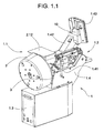
- Fig. 1.1 shows the inventive device for Tüllenbe conductedung, hereinafter called Tüllenbe conferenceer 1, consisting of a Tüllenmodul 1.1, a component module 1.2, a controller 1.3 and a base module 1.4.
- Assembly module 1.2 and control 1.3 are part of the base module 1.4.
- the grommet module 1.1 is separable by means of lever 1.41 from the base module 1.4.
- On the base module 1.4 is also a boom 1.42 with a control panel 1.43 and an ejector 10th
- Fig. 1.2 shows the Tüllenbe Divisioner 1 with detached sleeve module 1.1, which is in operation by means of a serving as a guide and holding device centering pin 1.11 in connection with the base module 1.4 and which is separable by means of lever 1.41 of the base module 1.4.
- the Tüllenmodul 1.1 consists essentially of a Tüllen amid 2 with a rotatable drum 2.1, a hopper 2.11 with cover 2.12, a support 3 for receiving the tulle-specific machine parts 11,30,31,34,41,42 and / or tools and a conveyor consisting from a conveyor belt 7 carrying a linear vibrating conveyor 4.
- a arranged on the base module 1.4 drive 5 offset the drum 2.1 in a rotational movement.
- the conveyor rail 7 is tulle-specific or fits only for tulle varieties of the same geometry. (Spouts with the same geometry and different colors).
- conveying blades are arranged by means of which grommets 17 for the assembly of electrical cables of the conveyor rail 7 can be fed, wherein the in Fig. 2 Further described conveyor rail 7 protrudes through an open end of the Tüllen shalls 2 at the higher end in this.
- the drum 2.1 is preferably made of transparent plastic, so that a visual control of Tüllenvorrates and the feeding process is possible.
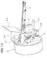
- Fig. 1.3 Below the centering 1.11 is a negative plug 1.12 is arranged, the pneumatic and electrical lines of Tüllenmoduls 1.1 via positive plug 1.16 of the base module 1.4 connects with pneumatic and electrical lines of the base module 1.4.
- Fig. 1.3 it can be seen that the drum 2.1 is tilted slightly downwards relative to the conveyor rail 7 on the grommet module 1.1. As a result of gravity, the grommets 17 in the drum always move toward the lower end of the drum 2, the feed vanes exhausting the drum to the last grommet and feeding the conveyor rail 7 arranged at the higher end of the drum 2.1.
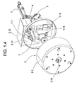
- Fig. 1.4 shows the Tüllenmodul 1.1 with the Tüllenmodul 1.1 separate drum 2.1.
- the drum 2.1 can be placed on a drive flange 1.13 of the sleeve module 1.1 and locked by means of a quick release 2.13 with the drive flange 1.13.
- the one end of the conveyor rail 7 protrudes at the higher end of the drum 2.1 in the drum 2.1.
- the Spouts 17 conveyed to the conveyor rail 7 by means of the conveyor blades are sorted in the correct position by a device 7.1, with the false grommets 17 being removed from the conveyor rail 7 by blowing away.
- Fig. 1.5 shows the patch module 1.1 placed on the base module 1.4 without the reservoir 2 and the funnel 2.11.
- the drive 5 is rotatably mounted about an axis 5.11 in the direction of arrow P1, wherein the drive 5 is pivotable in the direction of arrow P1 against a spring force.
- a pinion 5.12 engages automatically after a change of Tüllenmoduls 1.1 in the teeth of a ring gear 1.14, wherein the ring gear 1.14 drives the drive flange 1.13.
- Centering pin 1.11, plug-in device 1.12, drive flange 1.13, ring gear 1.14, hopper 2.11, carrier 3 and vibratory conveyor 4 are arranged on a housing 1.15 of Tüllenmoduls 1.1.
- the housing 1.15 closes off the drum 2.1 by means of a flange, together they form the tulle storage 2.
- Fig. 1.6 shows a receiving device 1.44 for receiving the centering pin 1.11.
- the receiving device 1.44 essentially comprises a housing 1.45 with a bore 1.46 into which the centering pin 1.11 fits.
- a circular notch 1.47 is provided, which fits on an actuatable bolt 1.48.
- the centering pin 1.11 is pushed into the hole 1.46 until the notch 1.47 is the same as the pin 1.48.
- bolt 1.48 is moved by lever 1.41 and lever linkage 1.49 into notch 1.47, with the releasable notch / bolt connection pushing and holding the grommet module 1.1 in the correct axial position. All Electric and pneumatic lines are also coupled when inserting the centering pin 1.11 (by means of plug-in device 1.12,1.16).
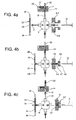
- the conveyor rail 7 in the longitudinal direction of a groove 16 whose cross-section approximately to the outline of the longitudinal section of a spout 17 (FIG. Fig. 4a-4e ) corresponds.
- the groove 16 is open at the rear end 18 of the conveyor rail 7, while it is closed at the front end 19 ( Fig. 4a-4e ).
- the front in the conveying direction P2 part of the groove 16 serves as a buffer 20, in which the spouts are stored in the correct position and which is covered with a cover plate 21.
- the cover plate 21 covers the groove 16 in half, so that the stored spouts are visible.
- the cover plate 21 has a projection 21.1 which completely covers the groove 16.
- the front end 19 of the conveyor rail 7 is covered with a plate 22 in which a bore 23 is provided, whose axis coincides with the axis of the first spout in the buffer 20.
- a vertical bore 24 (FIG. Fig. 4a-4e ) is provided in the conveyor rail 7, whose axis also coincides with the axis of the first spout, and whose diameter is smaller than that of the spout 17.
- a sorting baffle 25 is provided with a groove 16 on one side interrupting recess 26 and a Ausblasdüse not shown. At 28 is arranged upstream of the sorting baffle 25 blowing nozzle.
- a light barrier is connected, whose light beam is symbolized by a dot-dash line 29.
- the rail may be provided with a plurality of parallel, obliquely to the conveying direction in the feed opening holes through which exits a continuous adjustable air flow.
- Fig. 3 . Fig. 3a show details of the assembly module 1.2.
- the ejection device 10 has a centering pin 30 that can be moved up and down, which can be driven pneumatically, for example.
- the rotating device 11, which is arranged below the conveyor rail 7, has four mandrels 31, which are offset by an angle of 90 ° from each other.
- the rotating device 11 can be further rotated stepwise by an angle of 90 ° by means of a stepping motor 32.
- the mandrels 31 have two different diameters, wherein the diameter in the region of the tip of the mandrel is the smaller.
- the rotary device 11 is arranged such that in each case a mandrel 31 in a first position I of the rotary device 11 with the vertical bore 24 (FIG. Fig. 4a-4e ) of the conveyor rail 7 is aligned.
- a Aufschiebetician is referred to, which has two mold plates 34, in each of which a half of a bore 35 is arranged, which is aligned in a second position II of the rotating device 11 each with a mandrel 31.
- the mold plates 34 are fastened to holders 36, which are pivotable about pivot points 37 and are resiliently connected to a carrier 39 via a spring 38.
- the slide-on unit 33 can be moved in a straight line (for example pneumatically) in the direction of the mandrel 31.
- An insertion head 40 has a spout receiving part 41 and a spreading part 42.
- the Tüllenfactteil 41 consists of two jaws 43, each having a half of a cylindrical recess 44, whose size is adapted to the shape of the spouts 17 to be processed.
- the jaws 43 are arranged radially in opposite directions (for example pneumatically) displaceable on a guide support 45.
- the expanding part 42 consists of two further jaws 46, each having one half of a sleeve-shaped projection 47 and a bore 48 extending therethrough.
- the bore 48 has on the side facing away from the sleeve-shaped projection 47 of the other jaws 46 a funnel-shaped extension 49 and is dimensioned so that the cable 13 to be assembled can be accommodated.
- the further jaws 46 are slidably disposed on a further guide support 50, wherein they are moved simultaneously with the jaws 43, for which purpose they are mechanically coupled to the jaws 43.
- the Tüllenabilityteil 41 and the Aufsp Sonteil 42 are arranged such that the cylindrical recess 44 and the bore 48 in a further position IV of the rotating device 11 are aligned with one of the mandrels 31, wherein the further position IV relative to the second position II by an angle of 180 ° is offset.
- the Tüllenabilityteil 41 is disposed within a U-shaped recess 50.1 of the other guide support 50 in the axial direction of the cylindrical recess 44 (for example, pneumatically) slidably.
- the further guide member 50 is connected to a housing 51 which can be displaced in the axial direction of the cylindrical recess 44 and bore 48 together with the Tüllenabilityteil 41 and the expanding part 42 (also, for example, pneumatically).
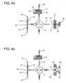
- a cable 13 is equipped with a grommet 17 as follows: After the grommets 17 are stored in the correct position on the conveyor rail 7, the foremost grommet 17 in the buffer 20 is conveyed via the vertical bore 24 ( Fig. 4d ). The spout 17 is now by means of the centering mandrel 30th pushed the ejector 10 on the tip of a mandrel 31 in the first position I ( Fig. 4a, 4b ). At the same time a seated on a position in the second position II mandrel 31 seated grommet 17 is pushed by the Aufschiebeech 33 on the thicker part of the mandrel 31, whereby it is expanded and placed in the correct position.
- the spreading member 42 is displaced relative to the Tüllenfactteil 41, wherein the spout 17 is stripped and clamped on the cable 13 ( Fig. 4d ). Thereafter, the jaws open 43 and 46, so that the assembled cable 13 can be removed and a new can be supplied.
- the rotating device 11 rotates through an angle of 90 °, wherein the empty mandrel 31 are rotated in the first position I and the already equipped mandrels 31 in the second and the other position II or IV ( Fig. 4e ).
- the tulle applicator 1 is converted as follows:
- the Tüllenmodul 1.1 contains all the items that are necessary for the assembly of the cable 13 with spouts of a particular Tüllensorte.
- Tüllen Entifacts
- Tüllen Entifacts
- the tulle-specific machine parts 11, 30, 31, 34, 41, 42 are arranged on the carrier 3.
- Tüllenmodul 1.1 is placed on the base module 1.4 (with corresponding spouts and tulle-specific machine parts and with the tulle-specific conveyor rail 7) and locked by means of levers 1.41.
- the centering 1.11 is plugged into a receptacle 1.44 of the base module 1.4, wherein all electrical and pneumatic lines are also coupled (by means of plug-in device 1.12,1.16).
- the grommet module 1.1 With the lever 1.41, the grommet module 1.1 is in the right place Axial position pressed and held.
- the coupling of the drive pinion 5.12 with the ring gear 1.14 is carried out automatically by means of the radially sprung drive 5.
- the tulle-specific machine parts 11,30,31,34,41,42 are mounted without tools.
- the quick release 2.13 of the drum 2.1 is opened before dropping the Tüllenmoduls 1.1.
- the spout module 1.1 (without drum) can be lifted out of the drum guide and inserted into a drum 2.1 with identical but differently colored spouts 17.
- the further assembly process is carried out as described above, except that the tulle-specific machine parts 11,30,31,34,41,42 are already mounted.
Landscapes
- Engineering & Computer Science (AREA)
- Manufacturing & Machinery (AREA)
- Feeding Of Articles To Conveyors (AREA)
- Installation Of Indoor Wiring (AREA)
Claims (10)
- Dispositif pour poser des manchons sur des câbles électriques (13), composé d'un module de base (1.4) pour porter un module de manchons (1.1) et un module de pose (1.2), le module de manchons (1.1) amenant les manchons à poser (17) dans la bonne position dans le module de pose (1.2), et le module de pose (1.2) posant les manchons (17) sur les câbles (13),
caractérisé en ce que le module de manchons (1.1) composé d'un réservoir de manchons (2) et d'un convoyeur (4, 7) est apte à être installé sur le module de base (1.4) par emboîtement. - Dispositif selon la revendication 1, caractérisé en ce que le module de manchons (1.1) comporte un boîtier (1.15) sur lequel est disposé un dispositif de guidage et de fixation (1.11) qui entre dans un dispositif de réception (1.44) du module de base (1.4).
- Dispositif selon la revendication 2, caractérisé en ce que le dispositif de guidage et de fixation comporte un axe de centrage (1.11) avec une encoche (1.47).
- Dispositif selon la revendication 2 ou 3,
caractérisé en ce que le dispositif de réception (1.44) comporte un boîtier (1.45) avec un perçage (1.46) dans lequel entre l'axe de centrage (1.11) pourvu de l'encoche (1.47), l'encoche (1.47) coïncidant avec une tige (1.48) et cette tige (1.48) étant apte à être amenée dans l'encoche (1.47) à l'aide d'un levier (1.41) et d'une transmission à levier (1.49). - Dispositif selon l'une des revendications précédentes, caractérisé en ce qu'il est prévu sur le boîtier (1.15) une bride d'entraînement (1.13) qui est apte à être entraînée à l'aide d'une couronne dentée (1.14) et sur laquelle un tambour (2.1) du réservoir de manchons (2) peut être installé par emboîtement.
- Dispositif selon la revendication 5, caractérisé en ce que la couronne dentée (1.14) est apte à être entraînée à l'aide d'un entraînement (5) disposé sur le module de base (1.4).
- Dispositif selon l'une des revendications précédentes, caractérisé en ce qu'il est prévu sur le boîtier (1.15) un dispositif d'emboîtement négatif (1.12) qui relie les lignes pneumatiques et électriques du module de manchons (1.1), par l'intermédiaire d'un dispositif d'emboîtement positif (1.16) du module de base (1.4), aux lignes pneumatiques et électriques du module de base (1.4).
- Dispositif selon l'une des revendications précédentes, caractérisé en ce que le boîtier (1.15) comporte un support (3) pour recevoir des pièces de machine (11, 30, 31, 34, 41, 42) spécifiques pour les manchons.
- Dispositif selon l'une des revendications précédentes, caractérisé en ce que les pièces de machine (11, 30, 31, 34, 41, 42) spécifiques pour les manchons peuvent être installées sur le module de pose (1.2) et enlevées de celui-ci sans outil.
- Dispositif selon l'une des revendications précédentes, caractérisé en ce qu'il est prévu sur le boîtier (1.15), comme convoyeur, un convoyeur vibrant (4) qui porte un rail de convoyeur (7).
Priority Applications (1)
| Application Number | Priority Date | Filing Date | Title |
|---|---|---|---|
| EP20060101224 EP1689049B1 (fr) | 2005-02-07 | 2006-02-02 | Dispositif pour appliquer des manchons sur câbles électriques |
Applications Claiming Priority (2)
| Application Number | Priority Date | Filing Date | Title |
|---|---|---|---|
| EP05405058 | 2005-02-07 | ||
| EP20060101224 EP1689049B1 (fr) | 2005-02-07 | 2006-02-02 | Dispositif pour appliquer des manchons sur câbles électriques |
Publications (2)
| Publication Number | Publication Date |
|---|---|
| EP1689049A1 EP1689049A1 (fr) | 2006-08-09 |
| EP1689049B1 true EP1689049B1 (fr) | 2008-11-12 |
Family
ID=36642684
Family Applications (1)
| Application Number | Title | Priority Date | Filing Date |
|---|---|---|---|
| EP20060101224 Expired - Lifetime EP1689049B1 (fr) | 2005-02-07 | 2006-02-02 | Dispositif pour appliquer des manchons sur câbles électriques |
Country Status (1)
| Country | Link |
|---|---|
| EP (1) | EP1689049B1 (fr) |
Cited By (6)
| Publication number | Priority date | Publication date | Assignee | Title |
|---|---|---|---|---|
| WO2011158145A1 (fr) | 2010-06-16 | 2011-12-22 | Schleuniger Holding Ag | Dispositif destiné à mettre en place des passe-câbles sur un câble |
| EP2731207A1 (fr) | 2012-11-07 | 2014-05-14 | Schleuniger Holding AG | Dispositif de application de passe-câbles sur un câble |
| US9352430B2 (en) | 2010-06-16 | 2016-05-31 | Schleuniger Holding Ag | Cable grommet fitting apparatus for cable |
| US9649737B2 (en) | 2012-09-12 | 2017-05-16 | Schleuniger Holding Ag | Machines and processes for fitting cable bushings |
| US9653865B2 (en) | 2011-09-29 | 2017-05-16 | Schleuniger Holding Ag | Method for fitting cables with cable sleeves |
| US11482823B2 (en) | 2018-11-06 | 2022-10-25 | Komax Holding Ag | Grommet station |
Families Citing this family (7)
| Publication number | Priority date | Publication date | Assignee | Title |
|---|---|---|---|---|
| US7963032B2 (en) | 2006-10-09 | 2011-06-21 | Komax Holding Ag | Method for determining the position of a wire fitting on a wire |
| EP1912296B1 (fr) * | 2006-10-09 | 2011-06-08 | Komax Holding AG | Procédé et dispositif destinés à déterminer la position d'un l'équipement de câble sur un câble |
| EP3336976B1 (fr) | 2016-12-16 | 2026-04-01 | Komax Holding Ag | Dispositif de traitement de câble |
| EP3970245B1 (fr) * | 2019-05-17 | 2023-11-29 | Metzner Maschinenbau GmbH | Procédé, dispositif et système pour la fabrication d'un câble électrique |
| EP3819994A1 (fr) * | 2019-11-08 | 2021-05-12 | Schleuniger AG | Support de module de préparation pour embouts |
| EP4533605A1 (fr) | 2022-06-02 | 2025-04-09 | komax Holding AG | Station passe-fil |
| EP4485716A1 (fr) | 2023-06-26 | 2025-01-01 | komax Holding AG | Module passe-fil |
Family Cites Families (6)
| Publication number | Priority date | Publication date | Assignee | Title |
|---|---|---|---|---|
| US4653182A (en) * | 1984-04-17 | 1987-03-31 | Sumitomo Electric Industries, Ltd. | Apparatus for fitting terminals and rubber stoppers on wires |
| GB8917145D0 (en) * | 1989-07-27 | 1989-09-13 | Amp Gmbh | Applying a bung seal to an electrical lead |
| DE4019483C1 (fr) * | 1990-06-19 | 1991-09-05 | Michels Gmbh & Co Kg, 4840 Rheda-Wiedenbrueck, De | |
| CH689272A5 (de) * | 1993-05-06 | 1999-01-15 | Komax Holding Ag | Einrichtung zur Tuellenbestueckung von elektrischen Kabeln. |
| DE59908252D1 (de) * | 1999-01-19 | 2004-02-12 | Pawo Systems Ag Unteraegeri | Verfahren und Einrichtung zur Tüllenbestückung |
| JP3706295B2 (ja) * | 2000-03-28 | 2005-10-12 | 矢崎総業株式会社 | ゴム栓挿入装置 |
-
2006
- 2006-02-02 EP EP20060101224 patent/EP1689049B1/fr not_active Expired - Lifetime
Cited By (10)
| Publication number | Priority date | Publication date | Assignee | Title |
|---|---|---|---|---|
| WO2011158145A1 (fr) | 2010-06-16 | 2011-12-22 | Schleuniger Holding Ag | Dispositif destiné à mettre en place des passe-câbles sur un câble |
| US9352430B2 (en) | 2010-06-16 | 2016-05-31 | Schleuniger Holding Ag | Cable grommet fitting apparatus for cable |
| US9496076B2 (en) | 2010-06-16 | 2016-11-15 | Schleuniger Holding Ag | Cable grommet fitting apparatus for cable |
| US9653865B2 (en) | 2011-09-29 | 2017-05-16 | Schleuniger Holding Ag | Method for fitting cables with cable sleeves |
| US10348031B2 (en) | 2011-09-29 | 2019-07-09 | Schleuniger Holding Ag | Apparatus for fitting cables with cable sleeves |
| US9649737B2 (en) | 2012-09-12 | 2017-05-16 | Schleuniger Holding Ag | Machines and processes for fitting cable bushings |
| US10427267B2 (en) | 2012-09-12 | 2019-10-01 | Schleuniger Holding Ag | Machine and processes for fitting cable bushings |
| US10814450B2 (en) | 2012-09-12 | 2020-10-27 | Schleuniger Holding Ag | Processes for fitting cable bushings |
| EP2731207A1 (fr) | 2012-11-07 | 2014-05-14 | Schleuniger Holding AG | Dispositif de application de passe-câbles sur un câble |
| US11482823B2 (en) | 2018-11-06 | 2022-10-25 | Komax Holding Ag | Grommet station |
Also Published As
| Publication number | Publication date |
|---|---|
| EP1689049A1 (fr) | 2006-08-09 |
Similar Documents
| Publication | Publication Date | Title |
|---|---|---|
| EP0626738B1 (fr) | Dispositif pour appliquer un manchon sur un câble électrique | |
| EP1689049B1 (fr) | Dispositif pour appliquer des manchons sur câbles électriques | |
| DE102017105016B3 (de) | Lagervorrichtung | |
| EP0534106B1 (fr) | Dispositif pour appliquer des manchons sur câbles électriques | |
| EP0956204B1 (fr) | Procede pour introduire des produits imprimes dans un produit principal plie | |
| EP1022821B1 (fr) | Méthode et dispositif pour appliquer des manchons | |
| DE69607816T2 (de) | Stangenvorschubvorrichtung, insbesondere für dünne Stangen in automatischen Zuführvorrichtungen | |
| DE69609365T2 (de) | Vorrichtung zum Fördern von Münzen | |
| DE4132998C2 (de) | Ansaug- und Transportvorrichtung | |
| EP3138778B1 (fr) | Machine de verrouillage de coques | |
| DE102017102618B4 (de) | Zuführeinrichtung | |
| WO2019029898A1 (fr) | Procédé et dispositif de fourniture de vis | |
| EP3651288B1 (fr) | Station de distribution | |
| DE2105333B2 (de) | Quetschmaschine | |
| EP2492238A1 (fr) | Dispositif destiné à fermer des récipients | |
| EP2709217B1 (fr) | Machine pour le montage de passe-câbles | |
| DE102015002502A1 (de) | Vorrichtung zum Wenden von formstabilen Behältern | |
| EP2930118B1 (fr) | Dispositif de manipulation de récipient et procédé de maintien, de préhension et/ou de rotation de récipients | |
| EP0661213B1 (fr) | Dispositif d'introduction d'étiquettes et procédé de fonctionnement | |
| CH689288A5 (de) | Verfahren und Vorrichtung zum Bestuecken von Steckergehaeusen. | |
| DE102004001751B4 (de) | Farbzufuhrvorrichtung für Druckmaschinen | |
| DE829570C (de) | Einrichtung an Tubenschliessmaschinen | |
| DE102009049806A1 (de) | Verfahren und Einrichtung zur elektrischen Isolationsprüfung sowie Verfahren und System zur Herstellung von Photovoltaikmodulen | |
| EP1162578A2 (fr) | Dispositif de tri pour pièces de monnaie avec un manchon comme réceptacle de collection des pièces | |
| DE102022111365B4 (de) | Wendeeinheit und Verfahren zum Wenden eines offenen Behälters mit flachen Produkten sowie System und Verfahren zum portionierten Abfüllen von flachen Produkten |
Legal Events
| Date | Code | Title | Description |
|---|---|---|---|
| PUAI | Public reference made under article 153(3) epc to a published international application that has entered the european phase |
Free format text: ORIGINAL CODE: 0009012 |
|
| AK | Designated contracting states |
Kind code of ref document: A1 Designated state(s): AT BE BG CH CY CZ DE DK EE ES FI FR GB GR HU IE IS IT LI LT LU LV MC NL PL PT RO SE SI SK TR |
|
| AX | Request for extension of the european patent |
Extension state: AL BA HR MK YU |
|
| 17P | Request for examination filed |
Effective date: 20070122 |
|
| AKX | Designation fees paid |
Designated state(s): CH DE FR GB IT LI |
|
| GRAP | Despatch of communication of intention to grant a patent |
Free format text: ORIGINAL CODE: EPIDOSNIGR1 |
|
| GRAS | Grant fee paid |
Free format text: ORIGINAL CODE: EPIDOSNIGR3 |
|
| GRAA | (expected) grant |
Free format text: ORIGINAL CODE: 0009210 |
|
| AK | Designated contracting states |
Kind code of ref document: B1 Designated state(s): CH DE FR GB IT LI |
|
| REG | Reference to a national code |
Ref country code: GB Ref legal event code: FG4D Free format text: NOT ENGLISH |
|
| REG | Reference to a national code |
Ref country code: CH Ref legal event code: EP |
|
| REG | Reference to a national code |
Ref country code: CH Ref legal event code: NV Representative=s name: INVENTIO AKTIENGESELLSCHAFT |
|
| REF | Corresponds to: |
Ref document number: 502006002037 Country of ref document: DE Date of ref document: 20081224 Kind code of ref document: P |
|
| PLBI | Opposition filed |
Free format text: ORIGINAL CODE: 0009260 |
|
| PLAX | Notice of opposition and request to file observation + time limit sent |
Free format text: ORIGINAL CODE: EPIDOSNOBS2 |
|
| 26 | Opposition filed |
Opponent name: SCHLEUNIGER HOLDING AG Effective date: 20090811 |
|
| PLBB | Reply of patent proprietor to notice(s) of opposition received |
Free format text: ORIGINAL CODE: EPIDOSNOBS3 |
|
| GBPC | Gb: european patent ceased through non-payment of renewal fee |
Effective date: 20100202 |
|
| PG25 | Lapsed in a contracting state [announced via postgrant information from national office to epo] |
Ref country code: GB Free format text: LAPSE BECAUSE OF NON-PAYMENT OF DUE FEES Effective date: 20100202 |
|
| PLBP | Opposition withdrawn |
Free format text: ORIGINAL CODE: 0009264 |
|
| PLBD | Termination of opposition procedure: decision despatched |
Free format text: ORIGINAL CODE: EPIDOSNOPC1 |
|
| PLBM | Termination of opposition procedure: date of legal effect published |
Free format text: ORIGINAL CODE: 0009276 |
|
| STAA | Information on the status of an ep patent application or granted ep patent |
Free format text: STATUS: OPPOSITION PROCEDURE CLOSED |
|
| 27C | Opposition proceedings terminated |
Effective date: 20110806 |
|
| REG | Reference to a national code |
Ref country code: FR Ref legal event code: PLFP Year of fee payment: 11 |
|
| REG | Reference to a national code |
Ref country code: FR Ref legal event code: PLFP Year of fee payment: 12 |
|
| REG | Reference to a national code |
Ref country code: FR Ref legal event code: PLFP Year of fee payment: 13 |
|
| PGFP | Annual fee paid to national office [announced via postgrant information from national office to epo] |
Ref country code: FR Payment date: 20200219 Year of fee payment: 15 |
|
| PG25 | Lapsed in a contracting state [announced via postgrant information from national office to epo] |
Ref country code: FR Free format text: LAPSE BECAUSE OF NON-PAYMENT OF DUE FEES Effective date: 20210228 |
|
| PGFP | Annual fee paid to national office [announced via postgrant information from national office to epo] |
Ref country code: DE Payment date: 20250226 Year of fee payment: 20 |
|
| PGFP | Annual fee paid to national office [announced via postgrant information from national office to epo] |
Ref country code: CH Payment date: 20250301 Year of fee payment: 20 |
|
| PGFP | Annual fee paid to national office [announced via postgrant information from national office to epo] |
Ref country code: IT Payment date: 20250225 Year of fee payment: 20 |
|
| REG | Reference to a national code |
Ref country code: CH Ref legal event code: H14 Free format text: ST27 STATUS EVENT CODE: U-0-0-H10-H14 (AS PROVIDED BY THE NATIONAL OFFICE) Effective date: 20260202 Ref country code: DE Ref legal event code: R071 Ref document number: 502006002037 Country of ref document: DE |