EP1700629A2 - Balançoire - Google Patents
Balançoire Download PDFInfo
- Publication number
- EP1700629A2 EP1700629A2 EP06003787A EP06003787A EP1700629A2 EP 1700629 A2 EP1700629 A2 EP 1700629A2 EP 06003787 A EP06003787 A EP 06003787A EP 06003787 A EP06003787 A EP 06003787A EP 1700629 A2 EP1700629 A2 EP 1700629A2
- Authority
- EP
- European Patent Office
- Prior art keywords
- rocker
- support
- rocker according
- shells
- pivot bearing
- Prior art date
- Legal status (The legal status is an assumption and is not a legal conclusion. Google has not performed a legal analysis and makes no representation as to the accuracy of the status listed.)
- Withdrawn
Links
Images



Classifications
-
- A—HUMAN NECESSITIES
- A63—SPORTS; GAMES; AMUSEMENTS
- A63G—MERRY-GO-ROUNDS; SWINGS; ROCKING-HORSES; CHUTES; SWITCHBACKS; SIMILAR DEVICES FOR PUBLIC AMUSEMENT
- A63G11/00—See-saws
Definitions
- the present application relates to a rocker with a movable about a pivot bearing bar, which can be used in particular as a toy for children use.
- rockers have become known, which can be used simultaneously as a rocker and carousel, since the beam is not only pivotally but also rotatably supported.
- the object of the present invention is to provide a rocker which is easy to produce.
- rocker This design allows the rocker to be both pivotable and rotatable.
- rocker is easy and inexpensive to produce.
- bearing shell consists of two half-shells.
- the two half-shells are received in a recess on the underside of the beam in particular form-fitting manner.
- the half shells are at least partially covered by fixed to the beam holding plates and thereby secured against falling out of the recess.
- the ball head is arranged at the upper end of a support which can be fixed with its lower end in or on a substrate.
- An inventive possibility of attachment provides that the support has at its lower end a connecting plate for connection to the ground.
- the support has at its lower end a particular tapered portion for insertion into the ground.
- This design is particularly suitable for a simple transportable embodiment of the invention. through In the tapered section, the rocker can be quickly opened and removed.
- rocker has a foot which can be fixed to the ground and having a receptacle for the support.
- the foot has a round or angular retaining ring arranged on top for receiving the support and that struts extend obliquely downward from the retaining ring to supports.
- the beam has at least two along a connecting line releasably interconnected sections. In this way, the length of the device during transport can be significantly reduced, thereby facilitating entrainment in a motor vehicle. In this way, the rocker invention is also suitable for taking on trips or on vacation.
- the connecting line runs transversely to the longitudinal axis of the beam and is arranged in the region of the pivot bearing.
- a further improvement is achieved in that the at least two sections are hinged together and can be fixed relative to each other via a lock.
- the rocker better if, according to the invention, the length of the beam is in particular telescopically adjustable.
- FIG. 1 shows a rocker 1 with a beam 2, which can be moved about a pivot bearing 3.
- the bar 2 is formed as an elongated support body which forms at each of its two ends seating surfaces 4.
- the seats 4 each have a handle 5 is assigned.
- Under the seat surface 4 are in each case adjacent to the end of the beam 2 projections 6 are formed, which point downwards and are used as rockers during stops and the rocking movement by support on the ground limit.
- the projections 6 can be made to reduce the impact load of an elastic and / or damping material, eg rubber.
- enlarged seat panels can also be provided on the beam 2.
- the beam 2 is made of wood and has a circular cross-section. However, other materials such as metal or plastic may be used. Instead of the round cross section also square cross sections or other profiled structures can be used.
- the pivot bearing 3 is arranged at the upper end of a support 7, which can be fixed with its lower end in or on a substrate.
- the support 7 on its underside for connection to the ground on a connecting plate 8, which is provided with holes 9 for fastening means.
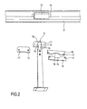
- FIG. 2 shows a partially disassembled state.
- This figure shows in detail the pivot bearing 3 with the provided at the upper end of the support 7 ball head 10, which is received in the mounted state in a bearing shell, which is formed from two half-shells 11, 11 '.
- the ball head on an upper extended support portion 12, which forms a spherical segment-shaped support surface.
- an elliptical shape or another suitable round shape may also be used.
- the ball head 10 has a neck portion 13 whose diameter is smaller than that of the support portion 12th
- the half shells 11, 11 'of the bearing shell receive the ball head 10 and have a correspondingly formed inner surface, which preferably has a spherical segmental shape in correspondence with the outer surface of the support portion 12.
- a correspondingly formed inner surface which preferably has a spherical segmental shape in correspondence with the outer surface of the support portion 12.
- the half-shells 11 and 11 ' are side by side, with the fastening holes 14 formed in the half-shells 11, 11' coming to rest on one another.
- the ball head 10 and the half-shells 11, 11 'of the bearing shell allow on the one hand a pivoting movement of the beam 2 relative to the support 7.
- the ball-receiving recess extends downwards so that a pivoting movement in the desired extent can take place.
- the design with ball head 10 and bearing shell 11, 11 ' that the beam can be rotated relative to the support 1 in a horizontal direction. This makes it possible to use the rocker not only for rocking but also as a kind of carousel.
- the attachment of the pivot bearing 3 in the beam 2 is effected in that the half shells 11, 11 ', which enclose the ball head 10, are received positively in a recess 15 on the underside of the beam 2.
- the half-shells 11, 11 ' have a substantially polygonal basic shape and can preferably be received in the recess 15 essentially without play.
- the pivot bearing 3 is thereby secured by retaining plates 16 against falling out.
- FIG. 2 shows two such holding plates, which have through holes 17 for fastening means which, in the mounted state, are in the bar 2 provided four mounting holes 18 extend.
- the holding plates 16 in this case have cutouts 19 through which the neck portion 13 extends in the mounted state.
- FIGs 3 and 4 show a further embodiment of a rocker 1, shown in a perspective view from below.
- the rocker 1 in this case has a bar 2, which may be provided with seats and handles as in the embodiment described in Figures 1 and 2 (not shown).
- the support 7 is determined in the embodiment shown in Figures 3 and 4 for insertion into the ground and has for this purpose at its lower end a tapered tip 20.
- the pivot bearing 3 is provided which, as in the embodiment described in FIGS. 1 and 2, has a ball head 10 fixed to the support 7.
- the beam 2 is not formed continuously, but is divided in the region of the pivot bearing 3. This makes it possible to transport the rocker in a simple manner and take for example in a normal motor vehicle on vacation.
- the ball head 10 is in turn received in a bearing shell consisting of two half-shells 11, 11 '.
- one half shell 11 is formed in one part of the beam 2 and the other half shell 11 'in the other part of the beam 2.
- the half-shells 11, 11 ' are directly in the bar 2 having a rectangular cross-section formed.
- the half shells 11, 11 ' may also be designed as inserts which are anchored in the beam 2.
- connection of the two parts of the beam 2 takes place via plate elements 21, which are provided on the two parts of the beam 2.
- the plate elements 21 are fixed by screws or other fastening means on the beam 2.
- Each two plate elements can be releasably connected to each other via bolts extending through eyelets. If the bolts 23 are removed on both sides, the two parts of the beam 2 are completely separated. If only one of the bolts 23 is removed, two of the plate elements 21 and the remaining pin 23 forms a kind of hinged hinge, which makes it possible to collapse the beam 2, as shown in Figure 4.
- Figures 5 and 6 show a plan view and side view of a foot 24 for the rocker shown in Figures 3 and 4.
- the foot 24 increases the stability of the rocker, especially for less load-bearing floors.
- the foot 24 has an opening forming a ring 25 through which the support 7 can extend.
- the ring 25 is held over four downwardly extending legs or struts 26.
- 26 supports with openings 27 are formed at the lower end of each leg, can be inserted through the fixing of the foot 24 nails, pegs or the like in the ground.
- the beam 2 can be designed such that its length can be adjusted telescopically. This not only has advantages in transportation, but also allows better use by people of different sizes or different weights. By doing namely, the length of the beam 2 is extended on one side, the distance of the seat surface 4 of the pivot bearing 3 can be varied and adjusted in accordance with the resultant lever arm.
Landscapes
- Pivots And Pivotal Connections (AREA)
- Mechanical Operated Clutches (AREA)
- Rolling Contact Bearings (AREA)
- Valve-Gear Or Valve Arrangements (AREA)
Applications Claiming Priority (1)
| Application Number | Priority Date | Filing Date | Title |
|---|---|---|---|
| DE200510010575 DE102005010575B3 (de) | 2005-03-04 | 2005-03-04 | Wippe |
Publications (2)
| Publication Number | Publication Date |
|---|---|
| EP1700629A2 true EP1700629A2 (fr) | 2006-09-13 |
| EP1700629A3 EP1700629A3 (fr) | 2006-09-27 |
Family
ID=36717056
Family Applications (1)
| Application Number | Title | Priority Date | Filing Date |
|---|---|---|---|
| EP06003787A Withdrawn EP1700629A3 (fr) | 2005-03-04 | 2006-02-24 | Balançoire |
Country Status (2)
| Country | Link |
|---|---|
| EP (1) | EP1700629A3 (fr) |
| DE (1) | DE102005010575B3 (fr) |
Cited By (1)
| Publication number | Priority date | Publication date | Assignee | Title |
|---|---|---|---|---|
| CN103263771A (zh) * | 2013-05-13 | 2013-08-28 | 苏州益童游乐设备有限公司 | 一种益智的跷跷板 |
Families Citing this family (1)
| Publication number | Priority date | Publication date | Assignee | Title |
|---|---|---|---|---|
| CN113827988B (zh) * | 2021-11-10 | 2023-03-10 | 泰州林峰户外用品有限公司 | 一种自带海洋球的趣味型儿童益智帐篷 |
Family Cites Families (11)
| Publication number | Priority date | Publication date | Assignee | Title |
|---|---|---|---|---|
| DE13959C (de) * | F. A. SCHMIDT in Leipzig, Berlinerstr. 3 | Schaukel-Carroussel | ||
| US666992A (en) * | 1900-10-10 | 1901-01-29 | Frank L Wright | Seesaw, merry-go-round, and lawn-seat. |
| FR589141A (fr) * | 1924-11-14 | 1925-05-23 | Balançoire pliante | |
| US1652993A (en) * | 1927-02-24 | 1927-12-13 | William W Neff | Merry-go-round |
| US2113488A (en) * | 1937-09-01 | 1938-04-05 | Milton | Seesaw apparatus |
| US2781193A (en) * | 1954-03-03 | 1957-02-12 | Marvin S Gowing | Teeter-totter |
| DE1693288U (de) * | 1954-11-05 | 1955-02-17 | Ver Fuer Kinderspielplaetze E | Sechsarmige drehwippe. |
| US2973961A (en) * | 1959-05-15 | 1961-03-07 | Behrens Karl | Seesaw |
| DE2038471A1 (de) * | 1970-08-03 | 1972-02-10 | Gerhard Esser | Wippe fuer Kinderspielplaetze,Gymnastik od.dgl. |
| US5403239A (en) * | 1993-12-03 | 1995-04-04 | Zimmers; Tighe | Wheeled seesaw device |
| GB9410852D0 (en) * | 1994-05-31 | 1994-07-20 | Steane Douglas A | Adjustable see-saw apparatus |
-
2005
- 2005-03-04 DE DE200510010575 patent/DE102005010575B3/de not_active Expired - Fee Related
-
2006
- 2006-02-24 EP EP06003787A patent/EP1700629A3/fr not_active Withdrawn
Cited By (2)
| Publication number | Priority date | Publication date | Assignee | Title |
|---|---|---|---|---|
| CN103263771A (zh) * | 2013-05-13 | 2013-08-28 | 苏州益童游乐设备有限公司 | 一种益智的跷跷板 |
| CN103263771B (zh) * | 2013-05-13 | 2016-02-17 | 陈潇菡 | 一种益智的跷跷板 |
Also Published As
| Publication number | Publication date |
|---|---|
| EP1700629A3 (fr) | 2006-09-27 |
| DE102005010575B3 (de) | 2006-10-19 |
Similar Documents
| Publication | Publication Date | Title |
|---|---|---|
| EP2962602A1 (fr) | Chaise | |
| DE202010013146U1 (de) | Schwingsessel | |
| DE19920386C2 (de) | Lager für eine umklappbare Rückenlehne | |
| DE69920802T2 (de) | Federgelenkstruktur | |
| EP1700629A2 (fr) | Balançoire | |
| DE10245173A1 (de) | Schaukelsessel | |
| DE102022132661B4 (de) | Liegestützgriff und Trainingssystem | |
| WO2000066390A1 (fr) | Palier | |
| EP2465387B1 (fr) | Articulation, notamment articulation pivotante | |
| DE102020106034A1 (de) | Scharnier | |
| DE69714910T2 (de) | Verstellvorrichtung | |
| DE60307996T2 (de) | Verbesserungen hinsichtlich einer spielvorrichtung | |
| DE4442719C2 (de) | Orthopädischer Lattenrost | |
| DE1529417B2 (de) | Schaukelteil | |
| EP0341344A2 (fr) | Meuble servant de siège | |
| EP3525627B1 (fr) | Meuble d'assise | |
| DE19913865A1 (de) | Schirmständer | |
| DE102023118570B4 (de) | Kopplungsvorrichtung | |
| EP0894457B1 (fr) | Système de chaises pour tribunes | |
| DE102009056524B4 (de) | Stehplatz-Sitzplatz-Kombination | |
| EP1150593B1 (fr) | Siege dynamique | |
| DE909422C (de) | Schaukel, insbesondere Kinderschaukel, mit wechselnder Antriebsrichtung | |
| DE19603932A1 (de) | Vorrichtung zur Sitzunterstützung | |
| DE3918626C2 (fr) | ||
| DE202023001187U1 (de) | Balance-Trainingsbank |
Legal Events
| Date | Code | Title | Description |
|---|---|---|---|
| PUAI | Public reference made under article 153(3) epc to a published international application that has entered the european phase |
Free format text: ORIGINAL CODE: 0009012 |
|
| PUAL | Search report despatched |
Free format text: ORIGINAL CODE: 0009013 |
|
| AK | Designated contracting states |
Kind code of ref document: A2 Designated state(s): AT BE BG CH CY CZ DE DK EE ES FI FR GB GR HU IE IS IT LI LT LU LV MC NL PL PT RO SE SI SK TR |
|
| AX | Request for extension of the european patent |
Extension state: AL BA HR MK YU |
|
| AK | Designated contracting states |
Kind code of ref document: A3 Designated state(s): AT BE BG CH CY CZ DE DK EE ES FI FR GB GR HU IE IS IT LI LT LU LV MC NL PL PT RO SE SI SK TR |
|
| AX | Request for extension of the european patent |
Extension state: AL BA HR MK YU |
|
| AKX | Designation fees paid | ||
| STAA | Information on the status of an ep patent application or granted ep patent |
Free format text: STATUS: THE APPLICATION IS DEEMED TO BE WITHDRAWN |
|
| 18D | Application deemed to be withdrawn |
Effective date: 20070328 |
|
| REG | Reference to a national code |
Ref country code: DE Ref legal event code: 8566 |