EP1701773B1 - Lösungsmittelverdampfer - Google Patents
Lösungsmittelverdampfer Download PDFInfo
- Publication number
- EP1701773B1 EP1701773B1 EP05701779A EP05701779A EP1701773B1 EP 1701773 B1 EP1701773 B1 EP 1701773B1 EP 05701779 A EP05701779 A EP 05701779A EP 05701779 A EP05701779 A EP 05701779A EP 1701773 B1 EP1701773 B1 EP 1701773B1
- Authority
- EP
- European Patent Office
- Prior art keywords
- receptacle
- vaporising
- solution
- temperature
- mouth
- Prior art date
- Legal status (The legal status is an assumption and is not a legal conclusion. Google has not performed a legal analysis and makes no representation as to the accuracy of the status listed.)
- Expired - Lifetime
Links
- 239000002904 solvent Substances 0.000 title claims description 43
- 238000000034 method Methods 0.000 claims abstract description 86
- 238000010438 heat treatment Methods 0.000 claims abstract description 35
- 230000001276 controlling effect Effects 0.000 claims abstract description 17
- 230000001105 regulatory effect Effects 0.000 claims abstract description 8
- 238000007789 sealing Methods 0.000 claims abstract description 5
- 230000008569 process Effects 0.000 claims description 42
- 150000002894 organic compounds Chemical class 0.000 claims description 20
- 238000000746 purification Methods 0.000 claims description 15
- 239000007788 liquid Substances 0.000 claims description 12
- 239000007787 solid Substances 0.000 claims description 10
- 230000008859 change Effects 0.000 claims description 8
- 230000002829 reductive effect Effects 0.000 claims description 8
- 230000015572 biosynthetic process Effects 0.000 claims description 7
- 238000004128 high performance liquid chromatography Methods 0.000 claims description 7
- 230000007246 mechanism Effects 0.000 claims description 7
- 238000003786 synthesis reaction Methods 0.000 claims description 7
- 238000005112 continuous flow technique Methods 0.000 claims description 6
- 238000003818 flash chromatography Methods 0.000 claims description 6
- 238000004808 supercritical fluid chromatography Methods 0.000 claims description 6
- 239000002243 precursor Substances 0.000 claims description 4
- 239000012453 solvate Substances 0.000 claims description 2
- 238000001704 evaporation Methods 0.000 abstract description 44
- 230000008020 evaporation Effects 0.000 abstract description 36
- 239000000243 solution Substances 0.000 description 131
- 239000000523 sample Substances 0.000 description 35
- 239000000463 material Substances 0.000 description 12
- 238000011161 development Methods 0.000 description 9
- 230000018109 developmental process Effects 0.000 description 9
- 230000005855 radiation Effects 0.000 description 8
- 238000012056 up-stream process Methods 0.000 description 7
- WEVYAHXRMPXWCK-UHFFFAOYSA-N Acetonitrile Chemical compound CC#N WEVYAHXRMPXWCK-UHFFFAOYSA-N 0.000 description 6
- 150000001875 compounds Chemical class 0.000 description 5
- IJGRMHOSHXDMSA-UHFFFAOYSA-N Atomic nitrogen Chemical compound N#N IJGRMHOSHXDMSA-UHFFFAOYSA-N 0.000 description 4
- 230000009471 action Effects 0.000 description 4
- 238000004821 distillation Methods 0.000 description 4
- 239000007789 gas Substances 0.000 description 4
- 230000003287 optical effect Effects 0.000 description 4
- 229920001343 polytetrafluoroethylene Polymers 0.000 description 4
- 230000004044 response Effects 0.000 description 4
- 238000012546 transfer Methods 0.000 description 4
- 238000013022 venting Methods 0.000 description 4
- 239000002699 waste material Substances 0.000 description 4
- XLYOFNOQVPJJNP-UHFFFAOYSA-N water Substances O XLYOFNOQVPJJNP-UHFFFAOYSA-N 0.000 description 4
- LYCAIKOWRPUZTN-UHFFFAOYSA-N Ethylene glycol Chemical compound OCCO LYCAIKOWRPUZTN-UHFFFAOYSA-N 0.000 description 3
- 238000009835 boiling Methods 0.000 description 3
- 239000005388 borosilicate glass Substances 0.000 description 3
- 230000015556 catabolic process Effects 0.000 description 3
- 238000004140 cleaning Methods 0.000 description 3
- 239000012141 concentrate Substances 0.000 description 3
- 238000006731 degradation reaction Methods 0.000 description 3
- 238000001035 drying Methods 0.000 description 3
- 239000002360 explosive Substances 0.000 description 3
- 238000005187 foaming Methods 0.000 description 3
- 239000008188 pellet Substances 0.000 description 3
- 238000003860 storage Methods 0.000 description 3
- 230000005540 biological transmission Effects 0.000 description 2
- 238000009529 body temperature measurement Methods 0.000 description 2
- 238000005119 centrifugation Methods 0.000 description 2
- 239000012468 concentrated sample Substances 0.000 description 2
- 238000009833 condensation Methods 0.000 description 2
- 230000005494 condensation Effects 0.000 description 2
- 238000005260 corrosion Methods 0.000 description 2
- 230000007797 corrosion Effects 0.000 description 2
- 230000003247 decreasing effect Effects 0.000 description 2
- 238000002474 experimental method Methods 0.000 description 2
- 229910052757 nitrogen Inorganic materials 0.000 description 2
- 230000009467 reduction Effects 0.000 description 2
- 239000003566 sealing material Substances 0.000 description 2
- 238000000926 separation method Methods 0.000 description 2
- VYPSYNLAJGMNEJ-UHFFFAOYSA-N silicon dioxide Inorganic materials O=[Si]=O VYPSYNLAJGMNEJ-UHFFFAOYSA-N 0.000 description 2
- 239000000126 substance Substances 0.000 description 2
- RTAQQCXQSZGOHL-UHFFFAOYSA-N Titanium Chemical compound [Ti] RTAQQCXQSZGOHL-UHFFFAOYSA-N 0.000 description 1
- 238000010521 absorption reaction Methods 0.000 description 1
- 230000001133 acceleration Effects 0.000 description 1
- 238000013459 approach Methods 0.000 description 1
- 238000010923 batch production Methods 0.000 description 1
- 230000008901 benefit Effects 0.000 description 1
- 239000013060 biological fluid Substances 0.000 description 1
- 230000006835 compression Effects 0.000 description 1
- 238000007906 compression Methods 0.000 description 1
- 230000001010 compromised effect Effects 0.000 description 1
- 239000000470 constituent Substances 0.000 description 1
- 238000011109 contamination Methods 0.000 description 1
- 238000012937 correction Methods 0.000 description 1
- 238000013461 design Methods 0.000 description 1
- 238000009826 distribution Methods 0.000 description 1
- 229940079593 drug Drugs 0.000 description 1
- 229920001971 elastomer Polymers 0.000 description 1
- 239000000806 elastomer Substances 0.000 description 1
- 239000012530 fluid Substances 0.000 description 1
- 239000006260 foam Substances 0.000 description 1
- 230000008014 freezing Effects 0.000 description 1
- 238000007710 freezing Methods 0.000 description 1
- 239000003517 fume Substances 0.000 description 1
- 239000005350 fused silica glass Substances 0.000 description 1
- 239000011521 glass Substances 0.000 description 1
- PCHJSUWPFVWCPO-UHFFFAOYSA-N gold Chemical compound [Au] PCHJSUWPFVWCPO-UHFFFAOYSA-N 0.000 description 1
- 239000010931 gold Substances 0.000 description 1
- 229910052737 gold Inorganic materials 0.000 description 1
- 229910052736 halogen Inorganic materials 0.000 description 1
- 238000007654 immersion Methods 0.000 description 1
- 238000010348 incorporation Methods 0.000 description 1
- 238000002347 injection Methods 0.000 description 1
- 239000007924 injection Substances 0.000 description 1
- 239000011810 insulating material Substances 0.000 description 1
- 230000000670 limiting effect Effects 0.000 description 1
- 238000005259 measurement Methods 0.000 description 1
- 239000010445 mica Substances 0.000 description 1
- 229910052618 mica group Inorganic materials 0.000 description 1
- 239000000203 mixture Substances 0.000 description 1
- 238000012986 modification Methods 0.000 description 1
- 230000004048 modification Effects 0.000 description 1
- 238000012544 monitoring process Methods 0.000 description 1
- 230000036961 partial effect Effects 0.000 description 1
- 238000001556 precipitation Methods 0.000 description 1
- 238000003825 pressing Methods 0.000 description 1
- 239000010453 quartz Substances 0.000 description 1
- 230000000717 retained effect Effects 0.000 description 1
- 229920006395 saturated elastomer Polymers 0.000 description 1
- 238000007790 scraping Methods 0.000 description 1
- 229910001220 stainless steel Inorganic materials 0.000 description 1
- 239000010935 stainless steel Substances 0.000 description 1
- 230000003068 static effect Effects 0.000 description 1
- 239000010936 titanium Substances 0.000 description 1
- 229910052719 titanium Inorganic materials 0.000 description 1
- 229910052721 tungsten Inorganic materials 0.000 description 1
- 239000010937 tungsten Substances 0.000 description 1
- -1 tungsten halogen Chemical class 0.000 description 1
- 238000011144 upstream manufacturing Methods 0.000 description 1
- 230000008016 vaporization Effects 0.000 description 1
- 238000010792 warming Methods 0.000 description 1
Images


Classifications
-
- B—PERFORMING OPERATIONS; TRANSPORTING
- B01—PHYSICAL OR CHEMICAL PROCESSES OR APPARATUS IN GENERAL
- B01D—SEPARATION
- B01D1/00—Evaporating
- B01D1/22—Evaporating by bringing a thin layer of the liquid into contact with a heated surface
- B01D1/222—In rotating vessels; vessels with movable parts
-
- B—PERFORMING OPERATIONS; TRANSPORTING
- B01—PHYSICAL OR CHEMICAL PROCESSES OR APPARATUS IN GENERAL
- B01D—SEPARATION
- B01D3/00—Distillation or related exchange processes in which liquids are contacted with gaseous media, e.g. stripping
- B01D3/10—Vacuum distillation
-
- G—PHYSICS
- G01—MEASURING; TESTING
- G01N—INVESTIGATING OR ANALYSING MATERIALS BY DETERMINING THEIR CHEMICAL OR PHYSICAL PROPERTIES
- G01N1/00—Sampling; Preparing specimens for investigation
- G01N1/28—Preparing specimens for investigation including physical details of (bio-)chemical methods covered elsewhere, e.g. G01N33/50, C12Q
- G01N1/40—Concentrating samples
- G01N1/4022—Concentrating samples by thermal techniques; Phase changes
- G01N2001/4027—Concentrating samples by thermal techniques; Phase changes evaporation leaving a concentrated sample
Definitions
- This invention relates to an apparatus and method for evaporating liquids, particularly, but not exclusively for the purposes of either increasing the concentration of a solution and/or for the complete removal of a solvent from a solution to leave a dry solid.
- a rotation evaporator In practice an apparatus for this purpose is known which is generally referred to as a rotation evaporator.
- An apparatus of this kind is disclosed in patent US 2,797,747 .
- the receptacle of this rotation evaporator formed as a round bottomed distilling flask in borosilicate glass, is rotated about its axis by means of a motor during distillation and is connected via a rotary union to a condenser.
- a vacuum source for example a diaphragm pump, is connected to the condenser.
- a so called heating bath is used, preferably having a liquid heat transfer medium that can be heated by means of an immersion heater.
- Rotation evaporators of this type offer rapid evaporation and have therefore been widely adopted in Chemistry and Biology laboratories they have limitations. Rotation evaporators require significant expertise and constant adjustment to achieve rapid evaporation without bumping (evaporating in an explosive manner), spitting or foaming of the solution being concentrated.
- the solution must be placed in a suitable receptacle for evaporation, typically a round bottom distillation flask; such a receptacle is impractical for future storage or transportation of concentrated or dry products. Often therefore, after the solution has been concentrated these dry products must be removed from the distilling flask and transferred to a more suitable receptacle, a vial with a screw cap for example. Commonly this transfer process is non trivial requiring multiple distillations and scraping of dry or semi-dry products from the distillation flask, thus requiring significant laboratory staffing time and resulting in loss of product and the potential for contamination.
- Centrifugal evaporators are also known, such as that described in GB 2 384 724A .
- sample tubes are mounted to a central rotor and spun about a central axis perpendicular to the axis of the sample tubes.
- the centrifugal forces acting on the solution in the tubes allows evaporation under vacuum without bumping.
- evaporators are slow batch processes and as such are unsuitable for incorporation into the modern automated synthesis and purification processes. These modern processes are predominantly sequential and require integrating with evaporation processes providing rapid evaporation of a small number of samples as opposed to slow evaporation of a large number of samples as offered by centrifugal evaporators.
- a typical application for evaporation might be the separation of 50 mg of solid from 30 ml of a solution of 50:50 (by volume) of water and Acetonitrile, for which the best centrifugal evaporators currently available would typically take about 16 hours to complete the evaporation and could dry 16 such samples in parallel. Centrifugal evaporators of this type are also relatively inconvenient to load/unload.
- centrifugal evaporators of this type concentrate or dry the solutions in the receptacle in which the solution was presented to the system, and thus cannot concentrate a volume of solution that is larger than the vial of choice into that vial.
- Centrifugal evaporators of this type are further limited in that when solutions are dried into solids, the solids take the form of hard pellets in the bottom of the receptacle. It is not only difficult to evaporate the final molecules of solvent from these pellets but the pellets themselves are very difficult to redissolve.
- An object of the invention is to further develop the apparatus and method of the kind described to provide an evaporation system capable of concentrating a solution that is contained in one receptacle, a round bottomed flask for example, into a receptacle of a form more suitable for storage and transportation, a screw cap vial for example. It is also an object of this invention to provide an apparatus and method that accomplishes the above objective in a manner so that it is easier and requires less laboratory staff and/or time to complete the concentration process.
- thermolabile fluids particularly biological fluids, which tend to become denatured and to foam when heated to boiling temperatures.
- a thermo-labile liquid having a volatile component is confined in a container so that when the container and its contents are centrifuged, a substantial liquid-gas interface will be formed.
- the pressure within the container is reduced to cause rapid volatilization of the volatile component at a temperature well below the denaturization temperature of the liquid.
- Centrifugation is performed at a speed sufficient to substantially eliminate foaming of the liquid during such volatilization.
- Moderate heating of the container and its contents to promote such volatilization may be provided.
- the centrifuging, gasevacuating, and heating steps are all performed simultaneously and are continued until the concentration of the liquid has been increased a predetermined extent.
- US 2,512, 604 discloses an evaporator in which the substance to be evaporated is subjected to heat and/or vacuum and rotating the receptacle about its vertical axis so as to spread the liquid to be evaporated in a uniformly thin layer over the inner wall of the receptacle.
- the receptacle is placed within a vacuum chamber and rotated whilst being subjected to RF energy,
- a rotary evaporator comprising a vessel having an orifice in its upper region, a holder for the vessel on which it is held, a stand having a rotary mount in which the holder is mounted so as to be able to rotate about an axis of rotation deviating from the vertical, a rotary drive for the holder, an outlet line for removing vapour from the vessel and a heating apparatus for heating a substance to be evaporated present in the vessel, the heating apparatus is a microwave heating apparatus having a heating chamber which is accessible through a door, the holder extending from the outside to the inside through the well of the heating chamber into this, and the rotary drive being arranged outside the heating chamber.
- DE 19841556 C1 discloses an evaporation apparatus for liquid sample material, the apparatus comprising a jar-shaped holder for a sample container, having an integral drive device for rotating the sample container inside the holder, and a heating device for warming the holder to a temperature which is above room temperature.
- a tightly closing lid is placed on the holder with an integral heating device which warms the lid to a temperature higher than room temperature.
- a suction device creates a partial vacuum in the space enclosed by the holder and lid.
- a gas supply system admits gas into the space to abstract sample vapour. It is a further object of this invention to provide an apparatus and method that reduces or eliminates the disadvantages of the prior art evaporators discussed above.
- the present invention provides an apparatus and method for concentrating and/or drying solutions in a receptacle which involves evaporation under low pressures whilst the receptacle is being rotated at high speed in a substantially vertical orientation.
- the high speed rotation allows the surface area of the solution in the receptacle to be maximised whilst using a standard sized/shaped receptacle, and is preferably also sufficient to prevent bumping.
- the vertical orientation of the receptacle also contributes to maximising the surface area, whilst allowing easy exchange of receptacles.
- an apparatus for concentrating solutions in a vaporising receptacle according to claim 1.
- the apparatus also includes means for dispensing a solution to be concentrated into the vaporising receptacle.
- the apparatus also includes sensing means to measure the temperature of the solution within the vaporising receptacle.
- the hot air heater means may also include a diverter for controlling the direction of the hot air flow and in one position directing said flow away from the receptacle.
- the apparatus also includes a control and regulating unit for controlling or regulating at least one of said rotation means, said vacuum pump, said dispensing means, said sensing means and said heating means.
- a control and regulating unit for controlling or regulating at least one of said rotation means, said vacuum pump, said dispensing means, said sensing means and said heating means.
- the vaporising receptacle is rotated (and the rotation means is operable to rotate the receptacle) at a speed sufficient to prevent the solution from bumping when heat is applied to the contents at a pressure below atmospheric conditions.
- the rotation means is operable to rotate the vaporising receptacle to speeds at which centrifugal force flattens the solution against the side walls of the receptacle.
- the rotation means is operable to rotate the vaporising receptacle at speeds of 2000 rpm or higher, and more preferably the rotation means is operable to rotate the vaporising receptacle at speeds of 3250 rpm or higher, and ideally at speeds of 6000 rpm or higher.
- the apparatus further comprises a removable vaporising receptacle.
- the removable vaporising receptacle is a standard clear glass vial of substantially cylindrical shape.
- the vial has one closed end, the other end having an axially located aperture (mouth) of a diameter smaller than that of the cylinder.
- the receptacle may be a 20ml scintillation vial.
- the apparatus of the present invention can be used with standard vials, and there is no need to transfer the concentrated solution or the dried solute from the receptacle to a further receptacle for transport or storage.
- the mouth through which the solution be concentrated is dispensed, remains positionally stationary whilst the receptacle is rotated (albeit rotating).
- This can be achieved by arranging the apparatus and the receptacle such that the rotational axis passes through the mouth of the receptacle,
- the sealing means of the apparatus may also remain positionally stationary, facilitating introduction and removal of the receptacle to/from the apparatus.
- the vaporising receptacle has features to enable a closure to be fixed to the open end.
- Such features may include a threaded portion or a return feature to enable the application of a crimp type closure.
- the temperature sensing means is a non-contact temperature sensor, and in particular the non-contact temperature sensing means may be a device known as an infra red pyrometer, which may be arranged to sense the temperature of the solution or dry products through the walls of the vaporising receptacle.
- the non-contact temperature sensing means may be a device known as an infra red pyrometer, which may be arranged to sense the temperature of the solution or dry products through the walls of the vaporising receptacle.
- Using a non-contact temperature sensor allows the receptacle to be rotated at high speeds without also having to consider the rotation of, or constraints on rotation resulting from, a contacting temperature sensor.
- a device to measure the temperature of the vapour directly may be located in the vapour flow immediately 'down stream' of the rotating vacuum connection or the vaporising chamber if this embodiment is adopted. Assuming that vapour is flowing, measuring the temperature of the vapour gives a good approximation to the temperature of the solution that the vapour is evaporating from.
- the heating means is a hot air blower employed to direct hot air onto the outside of the vaporising receptacle.
- the vaporising receptacle is sealed by pressing the open aperture against a seal that is itself connected to a rotating vacuum connection.
- This rotating vacuum connection facilitates the connection to the vacuum pump.
- the vial may be contained within a sealed vaporising chamber with a connection between this vaporising chamber and the vacuum pump.
- the apparatus may further comprise means for engaging and disengaging a vaporising receptacle with the apparatus.
- This means for engaging and disengaging may be manually or automatically operated. This means may also provide for simple or automated replacement of the receptacle with a further (e.g. empty) receptacle.
- a level sensing means may be employed to detect the level of the solution within the vaporising receptacle.
- the level sensing means is used to detect the level of the solution only when the vaporising receptacle is substantially stationary.
- the level sensing means may be a non-contacting optical device.
- the level sensing means may be a contact sensing device employing the know principle of measuring changes in conductivity to detect the surface of the solution.
- the solvent can be re-used as appropriate, and the emission of the apparatus controlled.
- a first condenser being located between the vaporising receptacle and the vacuum pump and a second condenser being connected to the exhaust of the vacuum pump.
- the control unit may be employed to ensure that the condition of at least one, and preferably all, of the following parameters within the vaporising receptacle is acceptable prior to dispensing a quantity of the solution: pressure, temperature and rotational speed.
- control unit may be employed to ensure the rotational speed of the vaporising receptacle is acceptable prior to reducing, to a level below atmospheric conditions, the pressure in the vaporising receptacle.
- control unit may prevent bumping by ensuring that a sufficient rotational speed is reached before low pressure evaporation commences.
- a pressure sensing means may be inserted into the conduit between said vaporising chamber, or rotary vacuum connection, and said vacuum pump.
- the electrical signal from this sensing means is connected to the control and regulating unit.
- a solenoid actuated valve may be placed into the conduit between said vaporising chamber or rotary vacuum connection and said vacuum pump to provide a means of controlling the pressure in said receptacle.
- valve employed before the vacuum pump is of the two port two position, normally closed type.
- a second solenoid actuated valve may be placed into a further conduit, said further conduit being connected into the first conduit at a location between said vaporising chamber or rotary vacuum connection and said vacuum pump.
- This second solenoid actuated valve may allow a rapid change of the pressure within the vaporising receptacle to atmospheric conditions.
- valve employed in said further conduit is of the two port two position, normally open type.
- the apparatus may further comprise a sample loop in which the solution to be concentrated is buffered for dispensing into the vaporising receptacle.
- the control unit may be appropriately configured to control the flow of solution into and out of the sample loop.
- the apparatus may further comprising a solution pump arranged to pump the solution to be concentrated into the vaporising receptacle, and in such cases, the control unit may operate the solution pump to pump the solution to be concentrated into the vaporising receptacle substantially continuously whilst the vaporising receptacle is being rotated.
- a solution pump arranged to pump the solution to be concentrated into the vaporising receptacle
- the means for dispensing the solution may include a nozzle.
- the nozzle and the solution pump are chosen such that the solution is dispensed into the vaporising receptacle in a continuous jet.
- the nozzle and the solution pump are chosen such that there is a pressure difference across the nozzle of at least 1 bar.
- the control unit may be appropriately configured to control the dispensing (and in particular the rate of dispensing) of the solution into the receptacle whilst rotation and evaporation are occurring.
- the control unit may also be configured to detect when the capacity of the receptacle for concentrated solution or dry solute is reached and interrupt the continuous dispensing.
- the control unit may be further configured to automatically replace the receptacle when the capacity is reached and recommence the continuous evaporation process.
- a further aspect of the present invention provides an apparatus for producing concentrated solutions or dry solvate including a first apparatus according to the first aspect above (which may have any combination of the preferred and optional features of the above aspect) and a second apparatus for performing a precursor process which supplies a solution to be concentrated to said first apparatus.
- the precursor process may be any one of: high performance liquid chromatography, purification of organic compounds by flash chromatography, purification of organic compounds by preparative scale supercritical fluid chromatography or synthesis of organic compounds using continuous flow techniques.
- Heating of the rotating vacuum connection may be required when evaporating some solvents to prevent condensation.
- the heating means may be such that its heat output is controlled by the magnitude of an electrical current, and current controlling means is provided adapted to control the said electric current to the heating means, and the signal from the temperature sensing means is employed to control the current controlling means and thereby the heat output from the heating means and in turn the temperature to which the concentrated sample is permitted to rise.
- the dispensing means is comprised of a conduit to feed the solution from the feed receptacle, a valve to regulate the flow of solution and a further conduit to feed the solution into the vaporising receptacle.
- valve employed in the dispensing means is of the two port two position normally closed type.
- the dispensing means may be comprised of a conduit to feed the solution from the feed receptacle, a volumetric pump to feed a measured quantity of solution, a valve to seal the pump and conduit from the vaporising receptacle and a further conduit to feed the solution into the vaporising receptacle.
- the dispensing means may be comprised of a pipette and syringe pump arrangement in a manner known per se.
- the vaporising receptacle may be moved either manually or by automated means to a position clear of the rotating vacuum connection giving the pipette access to dispense a measured quantity of solution into the receptacle.
- the dispensing means can be used in conjunction with the apparatus to complete a series of automated dispense and concentrate cycles. By this process a total volume of solution many times greater than the volume of the vaporising receptacle can be concentrated into a single vaporising receptacle.
- a total volume of solution many times greater than the volume of the vaporising receptacle can be concentrated into a single vaporising receptacle.
- the contents of a 250 ml round bottom flask may be either concentrated or dried completely into a single 20 ml scintillation vial.
- the receptacle may be supported to rotate about an axis that is at an angle to the longitudinal axis of the vaporising receptacle itself.
- the aperture is arranged to run true while the closed end is arranged to rotate in an eccentric matter.
- An advantage of this arrangement is that the solids dried from solution are deposited predominately at a location close to the closed end of the vaporising receptacle.
- the angle between the rotational axis and the longitudinal axis of the vaporising receptacle is between 0 and 6 degrees.
- a further aspect of the present invention provides a method of concentrating a solution according to claim 28.
- the step of maintaining the temperature of said vaporising receptacle within a predetermined range continues until a portion of the solvent has evaporated.
- the vaporising receptacle is rotated at a speed sufficient to prevent the solution from bumping when heat is applied to the contents at a pressure below atmospheric conditions.
- the vaporising receptacle is rotated at speeds sufficient for centrifugal force to flatten the solution against the side walls of the receptacle.
- the vaporising receptacle is rotated at speeds of 2000 rpm or higher, more preferably at speeds of 3250 rpm or higher, and ideally at speeds of 6000 rpm or higher.
- the step of maintaining the temperature may further include controlling a diverter mechanism which allows the air flow from the hot-air heater to be directed onto or away from the vaporising receptacle.
- the step of rotating the receptacle at high speed may be commenced before or after the solution has been dispensed into said receptacle.
- the step of maintaining the temperature of receptacle may include sensing the temperature of the receptacle with a non-contact temperature sensor.
- the receptacle used preferably has a mouth at one end through which the solution is dispensed into the receptacle and evaporated solvent is withdrawn from the receptacle, the rotation of the receptacle being such that said aperture remains substantially positionally stationary when the receptacle is rotated. This can be achieved by having the rotational axis pass through the mouth.
- the receptacle is substantially rotationally symmetric about a longitudinal axis, and the rotational axis is titled relative to that longitudinal axis. If these axes are tilted relative to each other, the angle of tilt is preferably between 0 and 6 degrees.
- the step of dispensing is performed substantially continuously throughout the concentration process.
- the method may further comprise the step of controlling either the rate at which the solution is dispensed into the vaporising receptacle, or the rate at which solvent is evaporated in said receptacle, such that a uniform film of solution is maintained over the side walls of the receptacle.
- the step of controlling includes sensing the temperature of two different portions of the receptacle, a first of said portions being an area of the receptacle proximate to the impact area of a heat source maintaining the temperature of the receptacle, and a second of said portions being an area of the receptacle which is distant from the impact area of said heat source, and adjusting either of said rates according to the rate of change in the difference between the two sensed temperatures.
- the method may further comprise the step of controlling the pressure in the receptacle to prevent phase change from liquid to solid as the solution is dispensed.
- the dispensed solution is supplied under pressure, more preferably at a pressure of at least 4 ⁇ 10 5 N/m 2 (4 bar).
- the solution is dispensed into the vaporising receptacle through a nozzle, and more preferably the nozzle and flow rate are selected and/or controlled such that there is a pressure difference of at least 1 bar across said nozzle.
- the method further includes the step of storing the solution to be concentrated in a sample loop prior to dispensing said solution into said receptacle,
- said solution may be provided to said receptacle or said sample loop directly from a preceding process.
- Said preceding process may be one of: high performance liquid chromatography; purification of organic compounds by flash chromatography; purification of organic compounds by preparative scale supercritical fluid chromatography; or synthesis of organic compounds by continuous flow techniques.
- the method of the present aspect is preferably performed using an apparatus according to any one of the preceding aspects, and the method may include further optional or preferred features which correspond to any combination of the optional or preferred features of the preceding aspects,
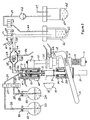
- a vaporising receptacle 1 has a substantially cylindrical portion 4 the axis of this cylindrical portion is labelled 5.
- the receptacle is closed at the lower end 2.
- An aperture 3 in the upper end is concentric with the cylindrical portion 4, having a diameter smaller than the internal diameter of the cylindrical portion 4.
- a feature 6 is provided for fixing a closure by, for example, manual operation, to the receptacle once the evaporation process is complete.
- the vaporising receptacle is manufactured from an impervious inert material so that it will not contaminate the sample or suffer corrosion; the material also allows transmission of infrared radiation.
- a suitable vaporising receptacle is readily available, being a 20 ml scintillation vial manufactured from borosilicate glass material,
- the vaporising receptacle 1 is supported on the end of a shaft 7, which is mounted for rotation about its axis in bearings 78 and 79, drive for which is provided by an electric motor 89.
- the bearings 78 and 79 and motor 89 are connected to housing 8 which is rigidly connected to carriage 9, which is mounted using a pair of linear stiding bearings (not shown) to slide along a pair of shafts indicated by 10.
- Rigidly attached to the lower end of shaft 10 is a block 17.
- At least one compression spring is constrained to slide along shaft 10, being constrained between block 17 and carriage 9, thereby capable of exerting an upwards force onto carriage 9 resisting downward movement.
- a user operable leaver 14 is pivotally mounted onto block 18 by pin 62, a further pin 15 is rigidly mounted into carriage 9 and is constrained to run within a slot in lever 14.
- Block 18 is rigidly mounted to shafts 10.
- the sealing material is an impervious inert material so that it will not contaminate the sample or suffer degradation when exposed to solvents, a perfluorinated elastomer is suitable, and examples of brand names are Isolast TM and Kalrez TM .
- Seal 13 is constrained by the rotating vacuum connection against vertical or lateral movement but is allowed to rotate freely about the vertical axis.
- seal 13 is located into a groove in shaft 52, which is mounted for rotation in bearings 54 and 55.
- a port 53 is provided running through the entire length of shaft 52 connecting the internal volume of vaporising receptacle 1 to the chamber 80 within the housing 58.
- the bearings 54 and 55 are mounted within housing 56 which is rigidly mounted to block 12, which is rigidly mounted to the upper portions of shafts 10.
- a sealing cap 58 is clamped to the top of body 56 by screws 60 and 61, an elastomeric seal 59 prevents leakage of air through the joint between cap 58 and body 56 into chamber 80.
- a shaft seal 57 is rigidly mounted within housing 56 to prevent leakage of air into chamber 80 between the housing 56 and the shaft 52.
- the sealing material is an impervious inert material so that it will not contaminate the sample or suffer degradation when exposed to solvents, a polytetraflouroethylene (PTFE) based seal material is suitable, a brand name is TurconTM
- a tube 22, welded into cap 58 passes completely through the port 53 projecting below the lower end of shaft 52 into the internal volume of the vaporising receptacle 1.
- a resistive heating device 40 and a temperature sensing device 41 are connected by a means providing good thermal contact to the outer surface of the rotary vacuum connection 11, for the purpose of heating the rotary vacuum connection 11 to a temperature determined by the control system 75.
- the port 32 in cap 58 is connected via conduits 33, 38, 44 and 69 to a vacuum pump 46, provided for the purpose of reducing the pressure within the vaporising receptacle causing the solvents contained within to boil at a maximum temperature that will not cause degradation to components contained within the solution, as such components are often thermo-labile. Typically for development of pharmaceutical drug compounds this upper temperature limit would be 37 degrees Celsius.
- the conduits 29 and 30 connected to tube 22 are in turn connected to isolating valves 27 and 28, each valve is connected a single solution supply vessel, valve 27 connected to solution supply vessel 63 by conduit 26 and valve 28 connected to solution supply vessel 64 by conduit 25.
- a source of infra red radiation 19 is arranged to focus infra red radiation through the cylindrical portion 4 of the vaporising receptacle 1 for absorption by the solution within the chamber 1.
- a hot air heater such as that illustrated in Figures 8 and 10 is provided instead of the infra red source 19.
- a suitable source of infra red radiation is a tungsten halogen lamp with gold plated parabolic reflector. Additional reflectors, not shown, are arranged to reflect transmitted radiation back into the solution and away from the shaft 7, housing 8, seal 13, shaft 52 and housing 11.
- an infra red pyrometer 21 is arranged to measure the temperature of the solution within the vaporising receptacle 1.
- an optical liquid sensing device 20 is arranged to detect when the level of the solution within the vaporising receptacle 1, when vaporising receptacle 1 is stationary, is at or above the level at which the optical sensing device is set to monitor.
- the level at which the optical sensing device is set to monitor can be adjusted by the user of the apparatus by a slider with pinch screw means, not shown.
- a vapour temperature sensing device 34 Connected between conduit 33 and conduit 38 is a vapour temperature sensing device 34. Attached to the sealed housing 90 is a resistive heating device 36 and a temperature sensing device 37 connected by a means providing good thermal contact to the outer surface of housing 90, for the purpose of heating the housing 90 to a temperature determined by the control system 75.
- a temperature sensing device 35 a thermocouple, is thermally but not electrically connected to a heat transfer device 81 which is mounted within the vapour flow and exchanges heat, by conduction, with the vapour. By this means the temperature sensing device 35 gives an electrical signal proportional to the temperature of the vapour within the housing 90.
- the temperature sensing device is protected from the solvent vapours present within the housing 90 by means of a polytetraflouroethylene (PTFE) sheath, not shown.
- Signal wires 84 connecting the temperature sensing device with the control system 75, pass through the housing 90 through a leak-free connector means.
- conduit 38 Connected into conduit 38 via conduit 83 is a pressure sensing device 39 for generating an electrical signal proportional to the pressure within the conduit 38.
- the pressure sensing device 39 is connected to the control system 75 by connection lines 85.
- valve 50 Connected into conduit 38 via conduit 82 is a shut off valve 50, used for venting air at atmospheric conditions drawn through conduit 51 into conduit 38.
- valve 50 is of the two port two position, normally open variety.
- a condenser 42 chilled by means of external power source may be incorporated into the apparatus between conduits 38 and 44.
- the purpose of the condenser 42 it to condense a proportion of solvent vapour, reducing the volume flow rate of vapour that must be pumped from the system by the vacuum pump 46.
- the temperature of the condenser 42 is maintained at a temperature below the temperature of the solution evaporating within the vaporising receptacle 1, this is achieved by feeding a mixture of chilled water and ethylene glycol through the jacket surrounding the condensed solvent 43 by a device known as a chiller, not shown.
- shut off valve 45 may be advantageously incorporated for isolating the vacuum pump 46 from the apparatus providing the means to control the pressure within the apparatus to a pre-determined level.
- valve 45 is of the two port two position, normally closed variety.
- the solvent resistant vacuum pump 46 is connected into conduit 69, the exhaust from the pump is connected into condenser 47.
- the purpose of the condenser 47 is to trap the solvent exhausted by the vacuum pump 46, reducing the potential for atmospheric pollution or explosive ignition of the exhaust vapours. Gases and some vapour exhausted from the condenser 47 pass through conduit 49 for connection into a fume cupboard or similar means, not shown.
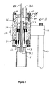
- Figure 5 shows an embodiment in which the vaporising receptacle is inclined with respect to the axis of rotation.
- the axis 72 is the axis of rotation for shaft 7
- the axis 73 is the axis of rotation for shaft 52
- the axis 5, as previously described, is the axis of the cylindrical portion of the vaporising receptacle 1.
- the axis 73 rotates substantially concentrically relative to axis 72, with an angle 70 between axis 72 and axis 5.
- the surface 71 of the solution is the position of the surface when the shaft 7 is rotating at the desired operational speed and before the volume of the solution has been reduced significantly by evaporation.
- the surface 74 is the position of the surface when the shaft 7 is rotating at the desired operational speed and when all the solvent has evaporated from the solution leaving a dry residue.
- the position and shape of the dry residue can be modified significantly by changing the angle 70. Best results are achieved when the angle 70 is between zero and six degrees, yet it is possible for the apparatus to function at angles between zero and 45 degrees.
- a vaporising chamber 67 in place of the rotary vacuum connection 11.
- the vaporising chamber 67 differs from the rotary vacuum connection 11 in that the vaporising chamber 67 does not rotate, when the lever 14 is released, the seal 66 is clamped between the vaporising chamber 67 and the base plate 86, a shaft seal 68 is now incorporated between the base plate 86 and the shaft 7 and the vaporising receptacle is located and retained in a collet 65 attached to the upper end of shaft 7.
- the walls of the vaporising chamber are manufactured from an impervious inert material so that it will not contaminate the sample or suffer corrosion; the material also allows transmission of infrared radiation. Suitable materials are borosilicate glass or quartz. Aside from the structural differences described, operation of this apparatus incorporating the vaporising chamber is identical to that for the embodiment which incorporates the rotating vacuum connection as described by figure 2 .
- valve 50 At the start of the evaporation process, the valve 50 is in the open position venting, to atmosphere, conduit 38 and the internal volume connected to it, valve 45 is in the closed position disconnecting the vacuum pump from conduit 44 and the internal volume connected to it, and the vacuum pump 46 is powered and evacuating the conduit 69, isolating valves 27 and 28 are in the closed position disconnecting the solution supply vessels from the conduit 22, the motor 89 and shaft 7 are stationary, and the infra red lamp 19 is de-energised.
- the maximum acceptable temperature for the solution is selected using the user interface 87, this data is transmitted to the control system 75, the rotating vacuum connection 11 is heated to the maximum allowable solution temperature by the action of heater 40 and controlled/detected by temperature sensor 41.
- the housing 90 is also heated to the maximum allowable solution temperature by the action of heater 36 and temperature sensor 37.
- One or more solution supply vessels are placed at locations indicated by 63 and 64.
- the lever 14 is moved in a downward direction and an empty vaporising receptacle 1 is placed onto the shaft 7.
- the lever 14 is then eased in an upward direction under the action of spring 16 and the vaporising receptacle 1 is forced against the seal 13 thus connecting, without leakage, the vaporising receptacle 1 to the rotating vacuum connection 11.
- the apparatus is now ready to commence the remainder of the evaporation processes in an automated manner, the start-button is activated on the user interface 87, and this data is transmitted to the control system 75, stage A is initiated.
- valve 45 is energised, connecting the vacuum pump and conduit 69 to conduit 44, the pressure is reduced throughout the connected conduits, and also within the vaporising receptacle 1.
- Valve 50 remains open, and thus air at atmospheric conditions flows through conduit 51 into conduit 38, in this manner the pressure within the vaporising receptacle 1 is regulated, being governed by the flow restriction inherent in the geometry of conduit 51.
- a pressure of approximately 10 4 N/m 2 (100 mbar) below the atmospheric conditions is suitable.
- stage B is initiated.
- valve 28 In stage B, valve 28 is opened, the pressure difference between the port 22 and the solution 24 causes the solution 24 to be forced through valve 28, conduit 30 and conduit 22 into the vaporising receptacle 1.
- the level sensor 20 detects the required level of solution in the vaporising receptacle 1
- valve 28 is closed, stage C is initiated. If the required level is not achieved then it is assumed that vessel 64 is empty, in this case, valve 28 is closed and valve 27 is opened, the process continues. If the required level is not achieved when valve 27 is open then it is assumed that all solution supply vessels are empty, and stage E is initiated.
- stage C the motor controller 76 ramps the motor up to full speed, the tachometer sensor feeds the motor speed back to the control system 75, and when full motor speed is achieved, valve 50 is closed and the pressure in the vaporising receptacle reduces rapidly.
- the minimum operational rotational speed for shaft 7 is defined as that speed sufficient to prevent the solution from bumping and foaming when heat is applied to the contents at a pressure at or below the saturated vapour pressure of the solution within the vaporising receptacle 1. It has been found, by experiment, that a speed in excess of that necessary to subject the solution to an acceleration of 150 times the normal gravitational attraction is required.
- the control system 75 uses the vapour temperature data from sensor 35 to control the average power supplied to the hot air heater 99 to maintain the vapour temperature as measured by sensor 35 to a target value which is slightly lower than the maximum acceptable temperature as set using the user interface 87. Once the target value of vapour temperature is achieved together with the average power supplied to the hot air heater 99 having decreased below a predetermined lower threshold level, the control system 75 assumes the majority of the solvent has evaporated from the solution, and stage D is initiated.
- stage D the valve 45 is moved to a closed position disconnecting the vacuum pump from conduit 44 and the internal volume connected to it, the valve 50 is moved to an open position venting, to atmosphere, conduit 38 and the internal volume connected to it.
- the speed of motor 89 is ramped down to stop.
- stage B is initiated once again. Stages B to D inclusive are repeated until all the solution contained within the solution supply vessels 63 and 64 has been transferred to the vaporising receptacle 1 and evaporated.
- stage E the motor controller 76 ramps the motor 89 up to operational speed, the tacho sensor feeds motor speed back to the control system 75, when the minimum operational rotational speed for shaft 7 is achieved, valve 50 is closed and the pressure in the vaporising receptacle reduces rapidly.
- the temperature of the contents within the vaporising receptacle 1, determined by the non-contact temperature sensor 21, is monitored continuously, and a further control algorithm within the control system 75 uses the temperature data from sensor 21 to control the average power supplied to the hot air heater 99 to maintain the temperature as measured by sensor 21 to a target value which is slightly lower than the maximum acceptable temperature as set using the user interface 87.
- the control system 75 Prior to taking each temperature measurement with the non-contact temperature sensor 21, the control system 75 ensures that the hot air heater 99 has been off for a pre-determined period of time. Once the average power supplied to the hot air heater 99 has decreased below a predetermined lower threshold level, the temperature as measured by the non-contact temperature sensor 21 is maintained at the maximum acceptable temperature, and the control system 75 starts a timer for the final drying period. Once the final drying period has been completed, the control system assumes that the product contained within the vaporising receptacle is dry, and stage F is initiated. In stage F, the valve 45 is moved to a closed position disconnecting the vacuum pump from conduit 44 and the internal volume connected to it, the valve 50 is moved to an open position venting, to atmosphere, conduit 38 and the internal volume connected to it.
- Figure 7 shows an alternative apparatus and method for heating the contents of the vaporising receptacle 1 in accordance with embodiments of the present invention, using a hot air heater 99 instead of infra-red lamp 19.
- a two stage axial fan 91 draws air at room temperature and forces the air past the resistive heating elements 94.
- a suitable fan is manufactured by Sanyo Denki and provides airflow 0.4 m 3 /min at a static pressure of 300 Pa.
- the heating element is mounted inside a thin walled tube 92 of low thermal conductivity. Stainless steel and titanium are both suitable materials for this tube.
- the heating element is electrically and thermally isolated from the thin walled tube 92 by a sleeve 93 of insulating material.
- a suitable material for this sleeve is Filamic tube FT19 supplied by Langtec Mica Ltd.
- a temperature sensing device 95 such as a thermister, positioned in the airflow as it exits the heating element, is used to measure the temperature of the air.
- a butterfly valve 97 is positioned between the vaporising receptacle 1 and the temperature sensor 95, and can be actuated to one of two positions, either to allow the hot air to heat the vaporising receptacle 1 or to divert the hot air out of the system through exit tube 98.
- the butterfly valve 97 is actuated by a solenoid, not shown, although alternatively a pneumatic cylinder could be used to actuate the butterfly valve 97.
- the butterfly valve 97 is sprung to return the valve to the divert position where air is diverted through tube 98.
- the air passes through a nozzle 96. This nozzle 96 can be easily removed and replaced and the size of the nozzle 96 can be chosen to suit the size of the vaporising receptacle 1.
- the fan 91 is powered, the heating element 94 is disconnected from the electrical supply and the butterfly valve is in the divert position.
- the vaporising receptacle 1 is rotated and the vacuum pump 46 is used to reduce the pressure in the vaporising receptacle sufficiently to cause the solvent within the vaporising receptacle 1 to boil, as described in more detail in other embodiments.
- the evaporation of the solvent within the vaporising receptacle 1 results in a rapid reduction of temperature of the vaporising receptacle, which is measured by the non-contact temperature sensor (e.g. an infra-red pyrometer) 21.
- the non-contact temperature sensor e.g. an infra-red pyrometer
- the butterfly valve In response to this reduction in temperature, the butterfly valve is activated allowing air to flow from the fan 91 to the vaporising receptacle 1.
- a control loop is enabled in which the heater power is adjusted to achieve and maintain a target temperature of the vaporising receptacle 1 as measured by the non-contact temperature sensor 21.
- the control loop utilises proportional, integral and derivative terms (commonly known as PID control) to ensure both rapid response and accurate temperature control. This control is maintained until the sample is dry.
- the power to the heater 94 is immediately switched off and at the same time the butterfly valve 97 is returned to the divert position.
- the pre-set value would typically be 3° C above the target temperature. It is most likely that the target temperature will be exceeded by the pre-set value once most of the solvent has evaporated and the demand for heat is dramatically reduced.
- the butterfly valve 97 is maintained in the divert position until the air temperature, as measured by the sensor 95, has reduced to a value lower that the target temperature.
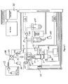
- Figure 8 shows an apparatus according to a first embodiment of the invention.
- the apparatus of Figure 8 is similar to that shown in Figure 2 and corresponding items are given the same references.
- the apparatus of Figure 8 has the following differences from that of Figure 2 .
- the vacuum pump 46 is driven using a variable speed drive which enables control of the pressure within the vaporising receptacle 1 without the valve 45.
- No vapour temperature sensor 90 is used.
- the vaporising receptacle 1 is supported on the end of shaft 7 which is in turn supported by a motorised lifting mechanism 108, At the uppermost end of tube 22 is connected a 5 port rotary valve 103, This valve 103 allows the volume within the vaporising receptacle 1 to be connected to either: a nitrogen supply 101 via a two port normally closed valve 102; to a blanked off port 116; to a further valve 104; or to connect the valve 104 directly to the waste container 100.
- the six port rotary valve 104 is known within the industry as an injection valve, Connected to one port of the rotary valve 104 is a syringe pump 106, with a further 3 port distribution valve 107.
- a sample loop 105 of sufficient capacity to accommodate the whole of the solution containing the sample of interest is connected across two of the ports in a manner commonly used within the industry.
- the solution to be evaporated is supplied from a preceding process to the port labelled '2' of the valve 104,
- Examples of preceding processes which may be used with the present embodiment include: purification of organic compounds by preparative scale High Performance Liquid Chromatography (HPLC); purification of organic compounds by Flash Chromatography; purification of organic compounds by preparative scale supercritical fluid chromatography (SFC); synthesis of organic compounds by continuous flow techniques.
- HPLC High Performance Liquid Chromatography
- SFC preparative scale supercritical fluid chromatography
- the motorised lifting mechanism 109 is in the fully lowered position, a clean vial is located onto the shaft 7, the rotatable shaft 7 is stationary, the tube 22 and the tube connecting valve 104 to 103 have been cleaned with pure solvent, valve 103 is positioned to connect tube 22 to the blanked off port 116 (position '2'), valve 102 is in the closed position, and valve 104 is switched to the load position (shown in Figure 8B ).
- the process is operating such that solution is flowing continually through the sample loop.
- the process indicates when solution to be evaporated is present within the sample loop, and also indicates the volume of this solution.
- valve 104 is switched to the 'inject' position (as shown in Figure 8 itself), in which the sample loop 105 is connected between the syringe pump 106 and the selection valve 103.
- the motorised lifting mechanism 109 is powered, lifting the vial until it engages with the elastomeric seal 13, and the drive motor 89 is energised to rotate the vial at high speed (in the range 3,250 to 10,000 rpm).
- valve 103 When the required speed has been achieved the valve 103 is positioned to connect the valve 104 directly to tube 22, and the syringe pump 106 is driven to pump pure solvent from receptacle 108 through the sample loop 105 and into the vaporising receptacle 1, carrying the solution present within the sample loop 105 into the vaporising receptacle 1.
- the evaporation process is then initiated: the vent valve 27 is closed, the vacuum pump 46 is powered to gradually reduce the pressure in the vaporising receptacle 1, the control loop is initiated to heat the contents of the vial in response to the feedback from the non-contact sensor 21.
- the vent valve 27 is closed, the vacuum pump 46 is powered to gradually reduce the pressure in the vaporising receptacle 1, the control loop is initiated to heat the contents of the vial in response to the feedback from the non-contact sensor 21.
- all the solvent has evaporated (which can be determined, for example, by monitoring the power required to maintain the temperature of the vaporising receptacle 1)
- valve 27 is opened to return the pressure within the vaporising receptacle 1 to atmospheric and a further dispense and evaporate cycle can be initiated.
- a cleaning cycle is initiated.
- This cleaning cycle is as follows: with the vaporising receptacle 1 maintained at vacuum, if required, the valve 103 is switched to connect the sample loop 105 to the waste container 100, the syringe pump 106 is used to pump a volume of pure solvent from the container 108 through the sample loop 105 and into waste container 100. Typically, the volume of pure solvent would be 4 times the volume of the sample loop 105 to ensure adequate cleaning.
- the valve 104 is returned to the load position, the sample loop is then available to accept the next sample.
- the pump 106 is stopped, the vacuum pump stopped, and the valve 27 opened.
- valve 103 When the pressure within the vaporising receptacle 1 has returned to atmospheric, the valve 103 is switched to connect tube 117 to tube 22, the syringe pump 106 is used to pump pure solvent through pipe 22 into the vaporising receptacle 1. 4 times the volume of tube 22 only is required. The syringe pump 106 is stopped, the valve 103 is switched to connect tube 22 to valve 102, valve 102 is open for a short duration to clear tube 22 of remaining solvent. Valve 102 is closed, valve 103 returned to connect tube 22 to port 116. The solvent in the vaporising receptacle 1 is then evaporated and dried fully in the manner already described above. Once the compound is fully dried the volume within the vaporising receptacle 1 is returned to atmospheric pressure, the spin motor 89 is turned off and the lift 109 returns the vaporising receptacle 1 to the load position.
- Figure 9 shows an apparatus according to a further embodiment of the invention.
- the apparatus of Figure 9 is similar to that shown in Figure 8 but the valve 104, the sample loop 105 and the syringe pump 106 have been replaced by an upstream process, generically indicated as 113.
- This process 113 supplies a solution to be evaporated from a continuously pumped source.
- the flow rate of solution from process 113 is chosen to be within the capability of the evaporator and it is therefore possible to evaporate the solution continuously, subject of course to the capacity limitations of the vaporising receptacle.
- the continuous evaporation in this embodiment means that solution is dispensed substantially continuously (and preferably continuously) into the vaporising receptacle 1 at the same time and at approximately the same rate at which solution is evaporating from the vaporising receptacle 1.
- the vaporising receptacle 1 must be maintained at pressures significantly below atmospheric while the solution is being pumped into the vaporising receptacle.
- a nozzle 112 is located at the point where solution within the tube 22 enters the vaporising receptacle 1.
- the up-stream process must supply solution under pressure. Typically a minimum working pressure of 4 ⁇ 10 5 N/m 2 (4 bar) is preferable.
- the size of the nozzle is selected to match the flow-rate in order to create a pressure difference across the nozzle greater than 10 5 N/m 2 (1 bar); and 2) The shape of the nozzle is selected to ensure the solution exits the nozzle as a jet not a series of drips.
- An example of a nozzle suitable for flow rates between 0.5 ml/minute and 2 ml/minute is 0.075 mm in diameter by 15 mm in length.
- a suitable material for the nozzle is fused silica tube such as that supplied by Upchurch Scientific Corp.
- Examples of preceding processes include: purification of organic compounds by preparative scale High Performance Liquid Chromatography (HPLC); purification of organic compounds by Flash Chromatography; purification of organic compounds by preparative scale supercritical fluid chromatography (SFC); synthesis of organic compounds by continuous flow techniques.
- HPLC High Performance Liquid Chromatography
- SFC preparative scale supercritical fluid chromatography
- the motorised lifting mechanism 109 is in the fully lowered position, a clean vial 1 is located onto the shaft 7, the rotatable shaft 7 is stationary, the tube 22 has been cleaned with pure solvent, valve 103 is positioned to connect tube 22 to the blanked off port indicated by '2', and the valve 102 is in the closed position.
- the up-stream process 113 indicates, for example by providing a signal to the control means, when it is about to start delivering solution.
- the motorised lifting mechanism 109 is powered, lifting the vial until it engages with the elastomeric seal 13, and the drive motor 89 is energised to rotate the vial at a high speed (in the range 3,250 to 10,000 rpm).
- the valve 103 is positioned to connect the tube 22 to the up-stream process 113.
- the vent valve 27 is closed, the pump is powered to gradually reduce the pressure in the vaporising receptacle 1, the control loop is initiated to heat the contents of the vial in response to the feedback from the non-contact sensor 21.
- the pressure is precisely controlled to a pre-set minimum value, this minimum value depending on the characteristics of the solution being evaporated.
- Pressure control is advantageous as it may prevent phase change from liquid to solid as the solution exits the nozzle. Phase change can be caused either by freezing of the solution (e.g. in the case of water if the pressure is reduced below 6 mbar) or by precipitation of solids from solution as a volatile constituent 'flashes off'.
- the first is a manual process whereby the rate of evaporation is adjusted by experiment to be a few percent slower than the rate of delivery. This process has been found to be effective where the total size of the sample is not more than 8 times the maximum capacity of the vial, but beyond this is generally not practical.
- the second method is an automated process and will be described in relation to the arrangement shown in Figure 10 .
- This method is suitable for a sample of any volume.
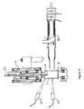
- Figure 10 shows a detail of an apparatus that enables an automated method for maintaining a continuous film of solution while evaporating solutions from a continuously pumped source.
- the arrangement is generally as shown in and as described in relation to Figure 9 but the single non-contact temperature sensor 21 is replaced by two non-contact temperature sensors 114 and 115.
- these sensors Preferably these sensors have a very small viewing area; an example of a suitable sensor is an infrared sensor supplied by Raytek Corp. (part number DKUMID02LT) having a 2.4 mm diameter viewing area at 80 mm distance.
- Sensor 114 is positioned to view an area of the vial close to the height at which the hot air heater 99 is applying heat to the surface of the vial.
- the second senor 115 is positioned to view an area at the upper end of the cylindrical portion of the vaporising receptacle 1.
- the viewing area for sensor 115 is away from the area of the vaporising receptacle 1 being heated by the hot air heater 99.
- sensor 115 measures a temperature close to the temperature of the boiling solvent within the vial while sensor 114 measures the temperature of the heated surface of the vial.
- sensor 115 may be measuring -5° C while sensor 114 is measuring 20° C. If the film of solvent is allowed to reduce in thickness, e.g. due to the rate of evaporation being greater than the rate of delivery, then as the thickness of the solvent film reduces then the temperature measured by sensor 115 increases until it approaches the temperature measured by sensor 114.
- the evaporation continues until the up-stream process indicates (e.g. by providing a signal to the control means) that delivery is complete.
- the valve 103 is then switched to connect the up-stream process directly to waste container 100 and simultaneously connect tube 22 to valve 102.
- Valve 102 is then opened for a short duration to clear the residual solution from tube 22 into vaporising receptacle.
- the up-stream process 113 stops dispensing.
- Valve 102 is closed and valve 103 is switched to connect tube 22 to the blanked off port 116.
- the evaporation process then continues until all solvent has been evaporated but at this stage pressure control is not critical. Once all the solvent has been evaporated and the compound in the vaporising receptacle 1 has been dried the process is stopped as previously described.
Landscapes
- Chemical & Material Sciences (AREA)
- Chemical Kinetics & Catalysis (AREA)
- Vaporization, Distillation, Condensation, Sublimation, And Cold Traps (AREA)
- Saccharide Compounds (AREA)
Claims (49)
- Vorrichtung zur Einengung von Lösungen in einem Verdampfungsbehälter (1), wobei der Behälter eine Öffnung (3) zur Entfernung des Dampfes aufweist, wobei die Vorrichtung Folgendes umfasst:Trägermittel (7) zum Tragen des Verdampfungsbehälters, wobei die Öffnung (3) des Behälters (1 ) nach oben gerichtet ist;ein Rotationsmittel (89), das betätigbar ist, um den solcherart getragenen Verdampfungsbehälter (1) bei hoher Geschwindigkeit um eine im Wesentlichen vertikale Rotationsachse (72) zu drehen;eine Vakuumpumpe (46) zur Reduktion des Drucks in dem Verdampfungsbehälter (1); undein Mittel (13) zum Abdichten der Öffnung des Verdampfungsbehälters (1) gegenüber der Vorrichtung, um die Vakuumpumpe (46) kommunizierend mit dem Inneren des Verdampfungsbehälters zu verbinden und den reduzierten Druck aufrecht zu erhalten;dadurch gekennzeichnet, dass die Vorrichtung ferner Folgendes umfasst:ein Heißluftgebläse (19, 99), das angeordnet ist, um einen heißen Luftstrom auf das Äußere des Behälters (1) zu richten.
- Vorrichtung nach Anspruch 1, die ferner ein Mittel (22) zur Abgabe einer einzuengenden Lösung in den Verdampfungsbehälter (1) umfasst.
- Vorrichtung nach Anspruch 1 oder 2, die ferner ein Abfühlmittel (21) zur Messung der Temperatur der Lösung in dem Verdampfungsbehälter (1) umfasst.
- Vorrichtung nach Anspruch 3, worin das Abfühlmittel (21) ein kontaktfreier Temperatursensor ist.
- Vorrichtung nach einem der vorangegangenen Ansprüche, worin das Heizmittel ferner eine Leitvorrichtung umfasst, um die Richtung des heißen Luftstroms zu steuern und in einer Position den Strom von dem Behälter weg zu leiten.
- Vorrichtung nach einem der vorangegangenen Ansprüche, die ferner eine Steuer- und Regulierungseinheit (75) zur Steuerung und Regulierung von zumindest einem aus Rotationsmittel (89), Vakuumpumpe (46), Abgabemittel, Abfühlmittel (21) und Heizmittel (19, 99) ausgewählten Element umfasst.
- Vorrichtung nach einem der vorangegangenen Ansprüche, worin das Rotationsmittel (89) betätigbar ist, um den Verdampfungsbehälter (1) in Geschwindigkeiten zu drehen, bei denen die Zentrifugalkraft die Lösung an den Seitenwänden des Behälters glättet.
- Vorrichtung nach Anspruch 7, worin das Rotationsmittel (89) betätigbar ist, um den Verdampfungsbehälter (1) bei Geschwindigkeiten von 2.000 U/min oder mehr zu drehen.
- Vorrichtung nach Anspruch 8, worin das Rotationsmittel (89) betätigbar ist, um den Verdampfungsbehälter (1) bei Geschwindigkeiten von 3.250 U/min oder mehr zu drehen.
- Vorrichtung nach einem der vorangegangenen Ansprüche, die ferner einen Verdampfungsbehälter (1) umfasst.
- Vorrichtung nach Anspruch 10, worin die Rotationsachse durch die Öffnung (3) des Verdampfungsbehälters (1) hindurch verläuft.
- Vorrichtung nach Anspruch 11, worin der Verdampfungsbehälter (1) im Wesentlichen zylinderförmig ist.
- Vorrichtung nach einem der Ansprüche 10 bis 12, worin der Verdampfungsbehälter (1) eine herkömmliche Phiole ist.
- Vorrichtung nach einem der vorangegangenen Ansprüche, die ferner Mittel (8, 9, 10) umfasst, um den Verdampfungsbehälter (1) mit der Vorrichtung in Eingriff zu bringen oder diesen Eingriff zu lösen.
- Vorrichtung nach einem der vorangegangenen Ansprüche, die ferner ein Füllstandabfühlmittel (20) umfasst, um den Füllstand der Lösung in dem Verdampfungsbehälter (1) zu detektieren, wenn der Behälter nicht rotiert.
- Vorrichtung nach einem der vorangegangenen Ansprüche, die ferner einen Kondensator (42, 47) umfasst.
- Vorrichtung nach Anspruch 16, worin zwei Kondensatoren vorliegen, wobei ein erster Kondensator (42) zwischen dem Verdampfungsbehälter (1) und der Vakuumpumpe (46) angeordnet ist und ein zweiter Kondensator (47) mit der Ableitung der Vakuumpumpe verbunden ist.
- Vorrichtung nach einem der vorangegangenen Ansprüche, die ferner eine Probenschleife (105) umfasst, in der die einzuengende Lösung gepuffert wird, um in den Verdampfungsbehälter (1) abgegeben zu werden.
- Vorrichtung nach einem der vorangegangenen Ansprüche, die ferner eine Lösungspumpe (106) umfasst, die angeordnet ist, um die einzuengende Lösung in den Verdampfungsbehälter zu pumpen.
- Vorrichtung nach Anspruch 19, worin die Steuereinheit die Lösungspumpe (106) betätigt, um die einzuengende Lösung im Wesentlichen kontinuierlich in den Verdampfungsbehälter (1) zu pumpen, während der Verdampfungsbehälter gedreht wird.
- Vorrichtung nach Anspruch 20, worin das Mittel zur Abgabe der Lösung eine Düse (112) umfasst.
- Vorrichtung nach Anspruch 21, worin die Düse (112) und die Lösungspumpe (106) so ausgewählt werden, dass die Lösung in einem kontinuierlichen Strahl in den Verdampfungsbehälter abgegeben wird.
- Vorrichtung nach Anspruch 21 oder 22, worin die Düse (112) und die Lösungspumpe (106) so gewählt werden, dass in der Düse eine Druckdifferenz von zumindest 105 N/m2 vorliegt.
- Vorrichtung nach einem der vorangegangenen Ansprüche, worin der Behälter (1) eine Längsachse (70) aufweist, um die er rotationssymmetrisch ist, und das Trägermittel (7) und das Rotationsmittel (89) so angeordnet sind, dass die Längsachse des Behälters von der Rotationsachse (72) weg geneigt ist.
- Vorrichtung nach Anspruch 24, worin die Neigung zwischen der Rotationsachse (72) und der Längsachse (70) des Behälters zwischen 0 und 6 Grad beträgt.
- Vorrichtung zur Herstellung von eingeengten Lösungen oder trockenem Solvat, einschließlich einer ersten Vorrichtung nach einem der vorangegangenen Ansprüche und einer zweiten Vorrichtung (113), die geeignet ist, um ein Vorläuferverfahren durchzuführen, und der ersten Vorrichtung eine einzuengende Lösung zuführt.
- Vorrichtung nach Anspruch 26, worin das Vorläuferverfahren ein beliebiges von folgenden ist: eine Hochleistungsflüssigkeitschromatographie, die Reinigung organischer Verbindungen mittels Flash-Chromatographie, die Reinigung organischer Verbindungen mittels präparativer überkritischer Fluidchromatographie und die Synthese organischer Verbindungen unter Anwendung kontinuierlicher Verfahren.
- Verfahren zur Einengung einer Lösung, das folgende Schritte umfasst:die Abgabe der Lösung in einen Verdampfungsbehälter (1), wobei der Behälter eine Öffnung (3) zur Entfernung von Dampf aufweist;das Tragen des Verdampfungsbehälters (1), wobei die Öffnung (3) nach oben gerichtet ist;das Drehen des auf diese Weise getragenen Verdampfungsbehälters (1) bei hoher Geschwindigkeit um eine im Wesentlichen vertikale Rotationsachse (72); unddas Reduzieren des Drucks in dem Verdampfungsbehälter, um zumindest einen Teil des Lösungsmittels zu verdampfen, dadurch gekennzeichnet, dass das Verfahren ferner folgende Schritte umfasst:das Abdichten der Öffnung (3) des Behälters (1) gegenüber der Vorrichtung, um die Vakuumpumpe (46) mit dem Inneren des Verdampfungsbehälters kommunizierend zu verbinden und den reduzierten Druck aufrecht zu erhalten; unddas Aufrechterhalten der Temperatur des Verdampfungsbehälters innerhalb eines vorbestimmbaren Bereichs durch die Steuerung des Heißluftgebläses (19, 99), das angeordnet ist, um einen Luftstrom auf das Äußere des Verdampfungsbehälters (1) zu richten.
- Verfahren nach Anspruch 28, worin der Schritt des Aufrechterhaltens der Temperatur ferner die Steuerung eines Ablenkmechanismus (97) umfasst, der ermöglicht, dass der Heißluftstrom des Heißluftgebläses (99) auf den Verdampfungsbehälter (1) oder von diesem weg gerichtet wird.
- Verfahren nach Anspruch 28 oder 29, worin der Verdampfungsbehälter (1) bei einer Geschwindigkeit gedreht wird, die ausreicht, damit die Zentrifugalkraft die Lösung an den Seitenwänden des Behälters glättet.
- Verfahren nach Anspruch 30, worin der Verdampfungsbehälter (1) bei einer Geschwindigkeit von 2.000 U/min oder mehr gedreht wird.
- Verfahren nach Anspruch 31, worin der Verdampfungsbehälter (1) bei einer Geschwindigkeit von 3.250 U/min oder mehr gedreht wird.
- Verfahren nach einem der Ansprüche 28 bis 32, worin der Schritt des Drehens des Behälters (1) bei hoher Geschwindigkeit beginnt, nachdem die Lösung in den Behälter abgegeben wurde.
- Verfahren nach einem der Ansprüche 28 bis 32, worin der Schritt des Drehens des Behälters (1) bei hoher Geschwindigkeit beginnt, bevor die Lösung in den Behälter abgegeben wird.
- Verfahren nach Anspruch 34, worin der Schritt der Abgabe im Verlauf des Einengungsverfahrens im Wesentlichen kontinuierlich erfolgt.
- Verfahren nach Anspruch 35, das ferner den Schritt des Steuerns der Rate, in der die Lösung in den Verdampfungsbehälter abgegeben wird, oder der Rate umfasst, in der das Lösungsmittel in dem Behälter (1) verdampft wird, sodass ein einheitlicher Film der Lösung auf den Seitenwänden des Behälters erhalten bleibt.
- Verfahren nach Anspruch 36, worin der Schritt des Steuerns das Abfühlen der Temperatur von zwei verschiedenen Abschnitten des Behälters, wobei es sich bei einem ersten der Abschnitte um einen Bereich des Behälters nahe des Bereichs handelt, in dem die Wärmequelle wirkt und die Temperatur des Behälters aufrecht erhält, und der zweite der Abschnitte ein Bereich des Behälters ist, der von dem Bereich, in dem die Wärmequelle wirkt, entfernt ist, und die Anpassung einer der Raten gemäß der Rate der Veränderung der Differenz zwischen den beiden abgefühlten Temperaturen umfasst.
- Verfahren nach einem der Ansprüche 35 bis 37, das ferner den Schritt des Steuerns des Drucks in dem Behälter (1) umfasst, um einen Übergang von flüssiger zu fester Phase während der Abgabe der Lösung zu verhindern.
- Verfahren nach einem der Ansprüche 35 bis 38, worin die abgegebene Lösung unter Druck zugeführt wird.
- Verfahren nach Anspruch 39, worin die abgegebene Lösung bei einem Druck von zumindest 4 x 10⁵ N/m2 zugeführt wird.
- Verfahren nach einem der Ansprüche 35 bis 40, worin die Lösung durch eine Düse (112) in den Verdampfungsbehälter (1) abgegeben wird.
- Verfahren nach Anspruch 41, worin die Düse (11) und die Durchflussrate so ausgewählt und/oder gesteuert werden, dass über die Düse eine Druckdifferenz von zumindest 105 N/m2 vorliegt.
- Verfahren nach einem der Ansprüche 28 bis 42, das vor der Abgabe der Lösung in den Behälter (1) ferner den Schritt des Lagerns der einzuengenden Lösung in einer Probenschleife (105) umfasst.
- Verfahren nach einem der Ansprüche 35 bis 43, worin die Lösung dem Behälter (1) oder der Probenschleife (105) unmittelbar durch ein Vorläuferverfahren (113) bereitgestellt wird.
- Verfahren nach Anspruch 44, worin das Vorläuferverfahren (113) eines von folgenden ist: eine Hochleistungsflüssigkeitschromatographie, die Reinigung organischer Verbindungen mittels Flash-Chromatographie, die Reinigung organischer Verbindungen mittels präparativer überkritischer Fluidchromatographie und die Synthese organischer Verbindungen unter Anwendung kontinuierlicher Verfahren.
- Verfahren nach einem der Ansprüche 28 bis 45, worin der Schritt des Aufrechterhaltens der Temperatur des Behälters (1) das Abfühlen der Temperatur des Behälters mit einem kontaktfreien Temperatursensor (21) umfasst.
- Verfahren nach einem der Ansprüche 28 bis 46, worin der Behälter (1) an einem Ende eine Öffnung (3) aufweist, durch die die Lösung in den Behälter abgegeben wird und verdampftes Lösungsmittel aus dem Behälter abgezogen wird, wobei die Rotationsachse (72) durch diese Öffnung hindurch verläuft.
- Verfahren nach einem der Ansprüche 28 bis 47, worin der Behälter im Wesentlichen um eine Längsachse (70) rotationssymmetrisch ist und diese Längsachse von der Rotationsachse (72) weg geneigt ist.
- Verfahren nach Anspruch 48, worin die Rotationsachse (70) von der Längsachse (72) des Behälters (1) in einem Winkel zwischen 0 und 6 Grad weg geneigt ist.
Applications Claiming Priority (2)
| Application Number | Priority Date | Filing Date | Title |
|---|---|---|---|
| GBGB0400192.1A GB0400192D0 (en) | 2004-01-06 | 2004-01-06 | Solvent evaporator |
| PCT/GB2005/000008 WO2005065799A1 (en) | 2004-01-06 | 2005-01-06 | Solvent evaporator |
Publications (2)
| Publication Number | Publication Date |
|---|---|
| EP1701773A1 EP1701773A1 (de) | 2006-09-20 |
| EP1701773B1 true EP1701773B1 (de) | 2011-03-30 |
Family
ID=31503481
Family Applications (1)
| Application Number | Title | Priority Date | Filing Date |
|---|---|---|---|
| EP05701779A Expired - Lifetime EP1701773B1 (de) | 2004-01-06 | 2005-01-06 | Lösungsmittelverdampfer |
Country Status (7)
| Country | Link |
|---|---|
| US (1) | US20080210384A1 (de) |
| EP (1) | EP1701773B1 (de) |
| JP (1) | JP4955400B2 (de) |
| AT (1) | ATE503537T1 (de) |
| DE (1) | DE602005027171D1 (de) |
| GB (2) | GB0400192D0 (de) |
| WO (1) | WO2005065799A1 (de) |
Cited By (1)
| Publication number | Priority date | Publication date | Assignee | Title |
|---|---|---|---|---|
| CN110538477A (zh) * | 2019-08-02 | 2019-12-06 | 北京师范大学 | 一种可多位点同时监测系统内蒸汽温度的旋转蒸发仪 |
Families Citing this family (27)
| Publication number | Priority date | Publication date | Assignee | Title |
|---|---|---|---|---|
| GB0225335D0 (en) * | 2002-10-31 | 2002-12-11 | Genevac Ltd | Temperature sensing in centrifugal evaporators |
| DE102006004927A1 (de) * | 2006-02-01 | 2007-08-09 | Börjes-Pestalozza, Henrich | Rotationsverdampfer |
| EP2089128A4 (de) * | 2006-12-08 | 2013-04-17 | Spectra Analysis Instr Inc | Verfahren und vorrichtung zur desolvierung einer fliessenden flüssigkeit |
| US8034214B2 (en) * | 2007-04-12 | 2011-10-11 | Tracera LLC | Reciprocating evaporator |
| US8562791B2 (en) | 2008-06-23 | 2013-10-22 | Verno Holdings, Llc | System for decontaminating water and generating water vapor |
| US9102545B2 (en) * | 2008-06-23 | 2015-08-11 | Verno Holdings, Llc | System for decontaminating water and generating water vapor |
| US11319218B2 (en) | 2009-06-22 | 2022-05-03 | Verno Holdings, Llc | System for decontaminating water and generating water vapor |
| US11608278B2 (en) | 2009-06-22 | 2023-03-21 | Verno Holdings, Llc | System for treating bio-contaminated wastewater and process for decontaminating a wastewater source |
| US10273168B2 (en) | 2009-06-22 | 2019-04-30 | Verno Holdings, Llc | System for processing water and generating water vapor for other processing uses |
| US11407655B2 (en) | 2009-06-22 | 2022-08-09 | Verno Holdings, Llc | System for decontaminating water and generating water vapor |
| WO2012087232A1 (en) * | 2010-12-23 | 2012-06-28 | Biotage Ab | Apparatus and method for thin-film lyophilization |
| DE102012221887A1 (de) * | 2012-11-29 | 2014-06-05 | Hans Heidolph Gmbh & Co. Kg | Verfahren und Vorrichtung zur Vakuumdestillation |
| JP5880482B2 (ja) * | 2013-02-13 | 2016-03-09 | 菱田 新悟 | 海水・川の水から飲料水を作る蒸留装置 |
| US9140971B2 (en) | 2013-10-31 | 2015-09-22 | Microvision, Inc. | Scanning laser proximity detection |
| DE102014107187A1 (de) * | 2014-05-21 | 2015-11-26 | Hans Heidolph Gmbh & Co. Kg | Rotationsverdampfer |
| JP6032655B2 (ja) * | 2014-07-10 | 2016-11-30 | 株式会社大澤商会 | 揮発性物質留去用アダプター |
| DE102014110343A1 (de) * | 2014-07-22 | 2016-01-28 | Hans Heidolph Gmbh & Co. Kg | Rotationsverdampfer |
| WO2017080113A1 (zh) * | 2015-11-10 | 2017-05-18 | 郝东辉 | 酸纯化器 |
| CN109154007B (zh) * | 2016-07-22 | 2023-01-03 | 佛兰芒技术研究所有限公司 | 通过发酵产生产物的方法和系统 |
| US10463983B2 (en) * | 2017-03-31 | 2019-11-05 | Picobrew, Inc. | Distillation and essence extractor insert for beer brewing machine |
| US11441978B1 (en) * | 2018-04-12 | 2022-09-13 | Elemental Scientific, Inc. | Automatic evaporative sample preparation |
| CN108465258B (zh) * | 2018-05-17 | 2023-11-14 | 常州工业及消费品检验有限公司 | 真空蒸发仪 |
| CN109529391B (zh) * | 2019-01-10 | 2024-10-01 | 北京澳维仪器有限公司 | 一种基于冷阱的旋转蒸发系统 |
| KR102019241B1 (ko) * | 2019-06-10 | 2019-11-04 | (주)엠오텍 | 전고체전지용 고체 전해질 생산을 위한 글로브 박스 시스템 |
| CN110478928B (zh) * | 2019-09-25 | 2024-04-16 | 北京师范大学 | 一种一次可准确定量浓缩多个样品的多旋转轴蒸发仪 |
| CN117462980A (zh) * | 2023-11-21 | 2024-01-30 | 北京聚兴泉源科技有限公司 | 一种超高效离心浓缩装置 |
| CN118142189B (zh) * | 2024-05-09 | 2024-07-09 | 云南冷萃科技有限公司 | 适用于咖啡生产加工的真空浓缩装置 |
Family Cites Families (25)
| Publication number | Priority date | Publication date | Assignee | Title |
|---|---|---|---|---|
| US2371166A (en) * | 1945-03-13 | Sealing means | ||
| US2512604A (en) * | 1944-10-03 | 1950-06-27 | Rca Corp | Art of concentrating pharmaceutical and other liquids |
| US2865455A (en) * | 1950-10-25 | 1958-12-23 | Pan American Petroleum Corp | Tubing scraper |
| US2843535A (en) * | 1953-10-21 | 1958-07-15 | Abbott Lab | Vacuum still |
| US2797747A (en) * | 1954-06-22 | 1957-07-02 | Francis J Rinderer | Evaporator |
| US3251635A (en) * | 1962-08-08 | 1966-05-17 | Edwin D Phillips | Liquid sealing means for stirring apparatus |
| ES404902A1 (es) * | 1972-07-06 | 1975-06-16 | Grifols Sa Lab | Procedimiento para concentrar liquidos termolabiles, espe- cialmente biologicos. |
| US4032118A (en) * | 1975-10-21 | 1977-06-28 | Phillips Edwin D | Sealing means for stirring apparatus |
| SU1741841A1 (ru) * | 1982-07-05 | 1992-06-23 | Всесоюзный Научно-Исследовательский И Конструкторский Институт Медицинской Лабораторной Техники | Способ концентрировани суспензий и растворов и устройство дл его осуществлени |
| JPS5990602A (ja) * | 1982-11-16 | 1984-05-25 | Tokyo Rika Kikai Kk | エバポレ−タ |
| JPS6174602A (ja) * | 1984-09-19 | 1986-04-16 | Shimadzu Corp | エバポレ−タ |
| US4826575A (en) * | 1985-11-18 | 1989-05-02 | Karamian Narbik A | Apparatus for production of high-purity water by microwave technology |
| US4913777A (en) * | 1987-12-11 | 1990-04-03 | Martin Parkinson | Solvent evaporator |
| FR2644356B1 (fr) * | 1989-03-20 | 1992-11-20 | Jouan | Procede de concentration d'echantillons par evaporation du solvant et evaporateur-concentrateur centrifuge pour la mise en oeuvre de ce procede |
| JPH0346413U (de) * | 1989-09-12 | 1991-04-30 | ||
| JPH03249902A (ja) * | 1990-02-28 | 1991-11-07 | Shimadzu Corp | 遠心濃縮機 |
| DE4038273A1 (de) * | 1990-11-30 | 1992-06-04 | Mls Gmbh | Vorrichtung zum ausloesen und/oder foerdern chemischer und/oder physikalischer prozesse |
| DE4223116A1 (de) * | 1992-04-30 | 1993-11-04 | Mikrowellen Labor Systeme | Vorrichtung zur verdampfungsbehandlung von vorzugsweise fluessigen stoffen, insbesondere reagenzstoffen, oder zum aufbereiten oder analysieren von probenmaterial |
| JP3230015B2 (ja) * | 1992-07-10 | 2001-11-19 | 東京理化器械株式会社 | 試験管エバポレータ |
| DE4319498A1 (de) * | 1993-04-29 | 1994-11-03 | Werner Lautenschlaeger | Rotationsverdampfer |
| US5840253A (en) * | 1996-06-20 | 1998-11-24 | Cytek Development Inc | Cell wash apparatus |
| WO2000014493A2 (en) * | 1998-09-05 | 2000-03-16 | Genevac Limited | Control of weight during evaporation of samples |
| DE19841556C1 (de) * | 1998-09-11 | 2000-03-23 | Volker Barkey | Eindampf-Vorrichtung für flüssiges Probenmaterial |
| DE19909228A1 (de) * | 1999-03-03 | 2000-09-07 | Lc Tech Gmbh | Verfahren und Vorrichtung zum Eindampfen von Flüssigkeitsproben auf ein bestimmbares Restvolumen |
| JP4422683B2 (ja) * | 2003-09-11 | 2010-02-24 | 株式会社シンキー | 撹拌脱泡装置 |
-
2004
- 2004-01-06 GB GBGB0400192.1A patent/GB0400192D0/en not_active Ceased
-
2005
- 2005-01-06 JP JP2006548375A patent/JP4955400B2/ja not_active Expired - Lifetime
- 2005-01-06 GB GB0500194A patent/GB2409824B/en not_active Expired - Lifetime
- 2005-01-06 EP EP05701779A patent/EP1701773B1/de not_active Expired - Lifetime
- 2005-01-06 WO PCT/GB2005/000008 patent/WO2005065799A1/en not_active Ceased
- 2005-01-06 DE DE602005027171T patent/DE602005027171D1/de not_active Expired - Lifetime
- 2005-01-06 US US10/585,469 patent/US20080210384A1/en not_active Abandoned
- 2005-01-06 AT AT05701779T patent/ATE503537T1/de not_active IP Right Cessation
Cited By (1)
| Publication number | Priority date | Publication date | Assignee | Title |
|---|---|---|---|---|
| CN110538477A (zh) * | 2019-08-02 | 2019-12-06 | 北京师范大学 | 一种可多位点同时监测系统内蒸汽温度的旋转蒸发仪 |
Also Published As
| Publication number | Publication date |
|---|---|
| GB2409824B (en) | 2006-05-31 |
| JP4955400B2 (ja) | 2012-06-20 |
| ATE503537T1 (de) | 2011-04-15 |
| WO2005065799A1 (en) | 2005-07-21 |
| GB2409824A (en) | 2005-07-13 |
| DE602005027171D1 (de) | 2011-05-12 |
| US20080210384A1 (en) | 2008-09-04 |
| JP2007517654A (ja) | 2007-07-05 |
| GB0400192D0 (en) | 2004-02-11 |
| GB0500194D0 (en) | 2005-02-16 |
| EP1701773A1 (de) | 2006-09-20 |
Similar Documents
| Publication | Publication Date | Title |
|---|---|---|
| EP1701773B1 (de) | Lösungsmittelverdampfer | |
| US5338409A (en) | Apparatus for distilling liquids in a vacuum | |
| US5792423A (en) | Headspace autosampler apparatus and method | |
| EP1049526B1 (de) | Vorrichtung und verfahren zur trocknung von makromoleküle enthaltenden lösungen | |
| US5932482A (en) | Headspace vial apparatus and method | |
| US5447077A (en) | Device for the evaporation treatment of preferably liquid substances, in particular reagents, or for the preparation or analysis of sample material | |
| US5269930A (en) | Apparatus and method for supercritical fluid extraction | |
| EP1297873B1 (de) | Zentrifugalverdampfer | |
| EP2024048B1 (de) | Verdampfer und zugehöriges betriebsverfahren | |
| US4465554A (en) | Hot jet evaporator | |
| JP7240449B2 (ja) | 自動式試料濃縮ユニット | |
| EP1997545A2 (de) | Steuerung von Kondensation in Kombination mit Verdampfung | |
| US7150807B2 (en) | Rotary evaporation with variable dosage metering | |
| EP2006005B1 (de) | Halbautomatische vorrichtung zur verdampfung von lösungsmitteln durch analysengas zum aufkonzentrieren von atmosphärenproben, das zur identifizierung und quantifizierung von organischen chemischen verbindungen mit toxischen eigenschaften ausgelegt ist | |
| JP4597375B2 (ja) | 可動試料棚を有する閉鎖反応室への供給システム | |
| WO2000013761A1 (en) | Vortex evaporator | |
| JP2018158292A (ja) | 揮発性物質留去装置及び揮発性物質の留去方法 | |
| US4240472A (en) | Apparatus for cleaning and coating capillary tubes useful in gas chromatography | |
| US11717767B2 (en) | Laboratory device for evaporating a substance | |
| EP0239622A1 (de) | Verfahren und apparat zur reihenbestimmung kleiner proben von peptiden und proteinen | |
| US11754583B2 (en) | Methods and apparatuses for generating trace vapors | |
| CN110168344A (zh) | 成分萃取装置 | |
| JP4545976B2 (ja) | 試料水分気化装置 | |
| GB2362590A (en) | Centrifugal evaporation apparatus |
Legal Events
| Date | Code | Title | Description |
|---|---|---|---|
| PUAI | Public reference made under article 153(3) epc to a published international application that has entered the european phase |
Free format text: ORIGINAL CODE: 0009012 |
|
| 17P | Request for examination filed |
Effective date: 20060714 |
|
| AK | Designated contracting states |
Kind code of ref document: A1 Designated state(s): AT BE BG CH CY CZ DE DK EE ES FI FR GB GR HU IE IS IT LI LT LU MC NL PL PT RO SE SI SK TR |
|
| DAX | Request for extension of the european patent (deleted) | ||
| 17Q | First examination report despatched |
Effective date: 20080326 |
|
| GRAP | Despatch of communication of intention to grant a patent |
Free format text: ORIGINAL CODE: EPIDOSNIGR1 |
|
| GRAS | Grant fee paid |
Free format text: ORIGINAL CODE: EPIDOSNIGR3 |
|
| GRAA | (expected) grant |
Free format text: ORIGINAL CODE: 0009210 |
|
| AK | Designated contracting states |
Kind code of ref document: B1 Designated state(s): AT BE BG CH CY CZ DE DK EE ES FI FR GB GR HU IE IS IT LI LT LU MC NL PL PT RO SE SI SK TR |
|
| REG | Reference to a national code |
Ref country code: GB Ref legal event code: FG4D |
|
| REG | Reference to a national code |
Ref country code: CH Ref legal event code: EP |
|
| REG | Reference to a national code |
Ref country code: IE Ref legal event code: FG4D |
|
| REF | Corresponds to: |
Ref document number: 602005027171 Country of ref document: DE Date of ref document: 20110512 Kind code of ref document: P |
|
| REG | Reference to a national code |
Ref country code: DE Ref legal event code: R096 Ref document number: 602005027171 Country of ref document: DE Effective date: 20110512 |
|
| REG | Reference to a national code |
Ref country code: NL Ref legal event code: VDEP Effective date: 20110330 |
|
| PG25 | Lapsed in a contracting state [announced via postgrant information from national office to epo] |
Ref country code: SE Free format text: LAPSE BECAUSE OF FAILURE TO SUBMIT A TRANSLATION OF THE DESCRIPTION OR TO PAY THE FEE WITHIN THE PRESCRIBED TIME-LIMIT Effective date: 20110330 Ref country code: LT Free format text: LAPSE BECAUSE OF FAILURE TO SUBMIT A TRANSLATION OF THE DESCRIPTION OR TO PAY THE FEE WITHIN THE PRESCRIBED TIME-LIMIT Effective date: 20110330 Ref country code: GR Free format text: LAPSE BECAUSE OF FAILURE TO SUBMIT A TRANSLATION OF THE DESCRIPTION OR TO PAY THE FEE WITHIN THE PRESCRIBED TIME-LIMIT Effective date: 20110701 |
|
| LTIE | Lt: invalidation of european patent or patent extension |
Effective date: 20110330 |
|
| PG25 | Lapsed in a contracting state [announced via postgrant information from national office to epo] |
Ref country code: FI Free format text: LAPSE BECAUSE OF FAILURE TO SUBMIT A TRANSLATION OF THE DESCRIPTION OR TO PAY THE FEE WITHIN THE PRESCRIBED TIME-LIMIT Effective date: 20110330 Ref country code: AT Free format text: LAPSE BECAUSE OF FAILURE TO SUBMIT A TRANSLATION OF THE DESCRIPTION OR TO PAY THE FEE WITHIN THE PRESCRIBED TIME-LIMIT Effective date: 20110330 Ref country code: SI Free format text: LAPSE BECAUSE OF FAILURE TO SUBMIT A TRANSLATION OF THE DESCRIPTION OR TO PAY THE FEE WITHIN THE PRESCRIBED TIME-LIMIT Effective date: 20110330 Ref country code: CY Free format text: LAPSE BECAUSE OF FAILURE TO SUBMIT A TRANSLATION OF THE DESCRIPTION OR TO PAY THE FEE WITHIN THE PRESCRIBED TIME-LIMIT Effective date: 20110330 |
|
| PG25 | Lapsed in a contracting state [announced via postgrant information from national office to epo] |
Ref country code: BE Free format text: LAPSE BECAUSE OF FAILURE TO SUBMIT A TRANSLATION OF THE DESCRIPTION OR TO PAY THE FEE WITHIN THE PRESCRIBED TIME-LIMIT Effective date: 20110330 |
|
| PG25 | Lapsed in a contracting state [announced via postgrant information from national office to epo] |
Ref country code: EE Free format text: LAPSE BECAUSE OF FAILURE TO SUBMIT A TRANSLATION OF THE DESCRIPTION OR TO PAY THE FEE WITHIN THE PRESCRIBED TIME-LIMIT Effective date: 20110330 |
|
| PG25 | Lapsed in a contracting state [announced via postgrant information from national office to epo] |
Ref country code: ES Free format text: LAPSE BECAUSE OF FAILURE TO SUBMIT A TRANSLATION OF THE DESCRIPTION OR TO PAY THE FEE WITHIN THE PRESCRIBED TIME-LIMIT Effective date: 20110711 Ref country code: RO Free format text: LAPSE BECAUSE OF FAILURE TO SUBMIT A TRANSLATION OF THE DESCRIPTION OR TO PAY THE FEE WITHIN THE PRESCRIBED TIME-LIMIT Effective date: 20110330 Ref country code: IS Free format text: LAPSE BECAUSE OF FAILURE TO SUBMIT A TRANSLATION OF THE DESCRIPTION OR TO PAY THE FEE WITHIN THE PRESCRIBED TIME-LIMIT Effective date: 20110730 Ref country code: SK Free format text: LAPSE BECAUSE OF FAILURE TO SUBMIT A TRANSLATION OF THE DESCRIPTION OR TO PAY THE FEE WITHIN THE PRESCRIBED TIME-LIMIT Effective date: 20110330 Ref country code: CZ Free format text: LAPSE BECAUSE OF FAILURE TO SUBMIT A TRANSLATION OF THE DESCRIPTION OR TO PAY THE FEE WITHIN THE PRESCRIBED TIME-LIMIT Effective date: 20110330 |
|
| PG25 | Lapsed in a contracting state [announced via postgrant information from national office to epo] |
Ref country code: NL Free format text: LAPSE BECAUSE OF FAILURE TO SUBMIT A TRANSLATION OF THE DESCRIPTION OR TO PAY THE FEE WITHIN THE PRESCRIBED TIME-LIMIT Effective date: 20110330 |
|
| PLBE | No opposition filed within time limit |
Free format text: ORIGINAL CODE: 0009261 |
|
| STAA | Information on the status of an ep patent application or granted ep patent |
Free format text: STATUS: NO OPPOSITION FILED WITHIN TIME LIMIT |
|
| PG25 | Lapsed in a contracting state [announced via postgrant information from national office to epo] |
Ref country code: DK Free format text: LAPSE BECAUSE OF FAILURE TO SUBMIT A TRANSLATION OF THE DESCRIPTION OR TO PAY THE FEE WITHIN THE PRESCRIBED TIME-LIMIT Effective date: 20110330 Ref country code: PL Free format text: LAPSE BECAUSE OF FAILURE TO SUBMIT A TRANSLATION OF THE DESCRIPTION OR TO PAY THE FEE WITHIN THE PRESCRIBED TIME-LIMIT Effective date: 20110330 |
|
| 26N | No opposition filed |
Effective date: 20120102 |
|
| REG | Reference to a national code |
Ref country code: DE Ref legal event code: R097 Ref document number: 602005027171 Country of ref document: DE Effective date: 20120102 |
|
| PG25 | Lapsed in a contracting state [announced via postgrant information from national office to epo] |
Ref country code: IT Free format text: LAPSE BECAUSE OF FAILURE TO SUBMIT A TRANSLATION OF THE DESCRIPTION OR TO PAY THE FEE WITHIN THE PRESCRIBED TIME-LIMIT Effective date: 20110330 |
|
| PG25 | Lapsed in a contracting state [announced via postgrant information from national office to epo] |
Ref country code: MC Free format text: LAPSE BECAUSE OF NON-PAYMENT OF DUE FEES Effective date: 20120131 |
|
| REG | Reference to a national code |
Ref country code: CH Ref legal event code: PL |
|
| REG | Reference to a national code |
Ref country code: IE Ref legal event code: MM4A |
|
| PG25 | Lapsed in a contracting state [announced via postgrant information from national office to epo] |
Ref country code: CH Free format text: LAPSE BECAUSE OF NON-PAYMENT OF DUE FEES Effective date: 20120131 Ref country code: LI Free format text: LAPSE BECAUSE OF NON-PAYMENT OF DUE FEES Effective date: 20120131 |
|
| PG25 | Lapsed in a contracting state [announced via postgrant information from national office to epo] |
Ref country code: IE Free format text: LAPSE BECAUSE OF NON-PAYMENT OF DUE FEES Effective date: 20120106 |
|
| PG25 | Lapsed in a contracting state [announced via postgrant information from national office to epo] |
Ref country code: BG Free format text: LAPSE BECAUSE OF FAILURE TO SUBMIT A TRANSLATION OF THE DESCRIPTION OR TO PAY THE FEE WITHIN THE PRESCRIBED TIME-LIMIT Effective date: 20110630 |
|
| PG25 | Lapsed in a contracting state [announced via postgrant information from national office to epo] |
Ref country code: TR Free format text: LAPSE BECAUSE OF FAILURE TO SUBMIT A TRANSLATION OF THE DESCRIPTION OR TO PAY THE FEE WITHIN THE PRESCRIBED TIME-LIMIT Effective date: 20110330 |
|
| PG25 | Lapsed in a contracting state [announced via postgrant information from national office to epo] |
Ref country code: LU Free format text: LAPSE BECAUSE OF NON-PAYMENT OF DUE FEES Effective date: 20120106 |
|
| PG25 | Lapsed in a contracting state [announced via postgrant information from national office to epo] |
Ref country code: HU Free format text: LAPSE BECAUSE OF FAILURE TO SUBMIT A TRANSLATION OF THE DESCRIPTION OR TO PAY THE FEE WITHIN THE PRESCRIBED TIME-LIMIT Effective date: 20050106 Ref country code: PT Free format text: LAPSE BECAUSE OF FAILURE TO SUBMIT A TRANSLATION OF THE DESCRIPTION OR TO PAY THE FEE WITHIN THE PRESCRIBED TIME-LIMIT Effective date: 20110330 |
|
| REG | Reference to a national code |
Ref country code: FR Ref legal event code: PLFP Year of fee payment: 12 |
|
| REG | Reference to a national code |
Ref country code: FR Ref legal event code: PLFP Year of fee payment: 13 |
|
| REG | Reference to a national code |
Ref country code: FR Ref legal event code: PLFP Year of fee payment: 14 |
|
| PGFP | Annual fee paid to national office [announced via postgrant information from national office to epo] |
Ref country code: DE Payment date: 20240123 Year of fee payment: 20 Ref country code: GB Payment date: 20240122 Year of fee payment: 20 |
|
| PGFP | Annual fee paid to national office [announced via postgrant information from national office to epo] |
Ref country code: FR Payment date: 20240117 Year of fee payment: 20 |
|
| REG | Reference to a national code |
Ref country code: DE Ref legal event code: R071 Ref document number: 602005027171 Country of ref document: DE |
|
| REG | Reference to a national code |
Ref country code: GB Ref legal event code: PE20 Expiry date: 20250105 |
|
| PG25 | Lapsed in a contracting state [announced via postgrant information from national office to epo] |
Ref country code: GB Free format text: LAPSE BECAUSE OF EXPIRATION OF PROTECTION Effective date: 20250105 |