EP1703349A2 - Offline-Lehrvorrichtung - Google Patents
Offline-Lehrvorrichtung Download PDFInfo
- Publication number
- EP1703349A2 EP1703349A2 EP06005176A EP06005176A EP1703349A2 EP 1703349 A2 EP1703349 A2 EP 1703349A2 EP 06005176 A EP06005176 A EP 06005176A EP 06005176 A EP06005176 A EP 06005176A EP 1703349 A2 EP1703349 A2 EP 1703349A2
- Authority
- EP
- European Patent Office
- Prior art keywords
- vision sensor
- teaching device
- robot
- measurement
- line teaching
- Prior art date
- Legal status (The legal status is an assumption and is not a legal conclusion. Google has not performed a legal analysis and makes no representation as to the accuracy of the status listed.)
- Withdrawn
Links
Images
Classifications
-
- G—PHYSICS
- G05—CONTROLLING; REGULATING
- G05B—CONTROL OR REGULATING SYSTEMS IN GENERAL; FUNCTIONAL ELEMENTS OF SUCH SYSTEMS; MONITORING OR TESTING ARRANGEMENTS FOR SUCH SYSTEMS OR ELEMENTS
- G05B19/00—Program-control systems
- G05B19/02—Program-control systems electric
- G05B19/42—Recording and playback systems, i.e. in which the program is recorded from a cycle of operations, e.g. the cycle of operations being manually controlled, after which this record is played back on the same machine
- G05B19/4202—Recording and playback systems, i.e. in which the program is recorded from a cycle of operations, e.g. the cycle of operations being manually controlled, after which this record is played back on the same machine preparation of the program medium using a drawing, a model
- G05B19/4207—Recording and playback systems, i.e. in which the program is recorded from a cycle of operations, e.g. the cycle of operations being manually controlled, after which this record is played back on the same machine preparation of the program medium using a drawing, a model in which a model is traced or scanned and corresponding data recorded
-
- B—PERFORMING OPERATIONS; TRANSPORTING
- B25—HAND TOOLS; PORTABLE POWER-DRIVEN TOOLS; MANIPULATORS
- B25J—MANIPULATORS; CHAMBERS PROVIDED WITH MANIPULATION DEVICES
- B25J9/00—Program-controlled manipulators
- B25J9/16—Program controls
- B25J9/1694—Program controls characterised by use of sensors other than normal servo-feedback from position, speed or acceleration sensors, perception control, multi-sensor controlled systems, sensor fusion
- B25J9/1697—Vision controlled systems
Definitions
- the present invention relates to an off-line teaching device used in a measuring operation using a vision sensor.
- Japanese Unexamined Patent Publication No. 8-167800 discloses a mounting device in which a component may be identified by detecting reflected or transmitted light, of an irradiating light, on a mark of the component.
- the measuring operation in the prior art takes much time because the measurement is carried out after an object and equipment such as a camera are actually prepared and arranged at predetermined positions.
- an actual control unit must be prepared for checking the measuring result by means of the actual motion of the robot.
- adjusting work, in the field is considerable in a system using a vision sensor. For example, it is necessary to adjust a parameter for detecting the object to be measured through a trial and error, in the field.
- an off-line teaching device to allow off-line arranging and adjusting of a vision sensor for measuring an object to be measured, the off-line teaching device comprising: a storing part for storing a measurement condition of the object; a displaying part for indicating an image of the vision sensor and an image of the object; a simulating part for generating the images of the vision sensor and the object on the displaying part and for calculating measurement data for measuring the object by means of the vision sensor and based on the measurement condition.
- the off-line teaching device may further comprise a choice assisting part for assisting the choice of an optical condition of a camera of the vision sensor, based on data in relation to the shape and the dimensions of the object.
- the off-line teaching device may further comprise a measurement executing part for carrying out measurement, by means of the vision sensor, on the displaying part based on the measurement data and a programming part for preparing a robot program defining the motion of a robot handling the object.
- the vision sensor may be attached to a movable part of the robot, otherwise, the vision sensor may be arranged at a fixed place.
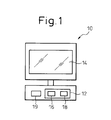
- Fig. 1 shows a typical constitution of an off-line teaching device 10 for a vision sensor according to the invention.
- the off-line teaching device 10 may be a processing device such as a personal computer.
- the teaching device includes a storing device 12, such as a ROM or hard disk, for storing data of the shapes and the dimensions of an object or a workpiece to be worked, a robot for carrying out various operations such as conveying, assembling, welding, deburring and sealing the workpiece, and a vision sensor for measuring the workpiece.
- the teaching device 10 also includes a display 14 for indicating images of the workpiece, the robot and the vision sensor.
- the teaching device 10 includes a simulation program 16 for generating the images of the workpiece, the robot and the vision sensor on the display 14 and for calculating measurement data of the vision sensor based on the arrangement of the images on the display, and a sensor program 18 for carrying out measurement on the display by the vision sensor based on the measurement data.
- These programs may be stored in the storing device 12.
- the teaching device 10 further includes a processing device or a CPU 19 for executing each process assigned to the teaching device.
- the teaching device 10 may include a keyboard (not shown) for inputting data by an operator.
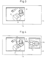
- Fig. 3 shows a typical example of the display.
- a window 14a displayed on the display 14 may be generated by executing the above simulation program 16.
- the window 14a includes the images of workpiece 20 positioned on a worktable 22 and the robot 30. These images may be indicated by using CAD data previously stored.
- the location of the images may be determined by the operator using the keyboard. Otherwise, the location may be previously set as a suitable initial location.
- the image data including the positions and the orientations of the workpiece 20 and the robot 30 may be fed to the sensor program 18.
- a measurement condition for example, a site of the workpiece to be measured, the style of the measurement (two-dimension or three-dimension), and/or the measurement accuracy
- a measurement condition for example, a site of the workpiece to be measured, the style of the measurement (two-dimension or three-dimension), and/or the measurement accuracy
- This step may be performed by the operator using the keyboard of the teaching device 10.
- optical conditions such as the types of a camera and a lens thereof to be used as the vision sensor, a field of the camera, a standoff, etc.
- the optical condition may be inputted by the operator, alternatively, an assist program for selecting the camera, capable of indicating a window on the display, may be previously installed in the teaching device 10, by which the operator may interactively input or check the type of the camera and the measurement accuracy, etc.
- the camera may be arranged on a fixed place or, alternatively, attached to a movable part, such as an arm, of the robot 30, depending on the above measurement condition.
- a motion compensating program for the robot on a base coordinate system or a tool coordinate system of the robot.
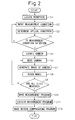
- step S4 the measurement accuracy expected by using the selected camera is estimated and, then, the result is compared to a desired accuracy included in the measurement condition inputted in step S2 (step S4).
- the procedure progresses to step S5, otherwise, returns to step S2 to reexamine the measurement condition.
- an image of the selected camera denoted by a numeral 40 is located at a suitable position (e.g., where the camera may roughly image the workpiece 20) in the window 14a (step S5).
- a suitable position e.g., where the camera may roughly image the workpiece 20
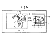
- an image of the workpiece 20, which is expected to be actually obtained by the camera 40 may be indicated on a window 14b. Therefore, the operator may visually check whether the selected camera 40 is suitable for the measurement.
- Teaching device 10 then carries out the model teaching of each site to be measured through steps S6 to S9.
- the camera 40 is moved and oriented so as to image a site or a model 24 to be measured in a field 42 of the camera 40 (step S6).
- an image of the site imaged by the camera is generated (step S7).
- the site in the window 14b is indicated as a featured model defined by a closing line 26 or pointed by a cross-shape marker 28.
- a floodlight device 44 such as a laser floodlight may be arranged on or near the camera 40, whereby three-dimensional images of the workpiece 20 and the model 24 may be obtained.
- step S8 When the image thus generated on the window 14b is considered to be valid, the model teaching is carried out (step S8). When a plurality of sites are to be measured, a set of steps S6 to S8 is repeated a certain number of times, the certain number being equal to the number of the plurality of sites (step S9). Therefore, a taught model corresponding to all of the sites may be obtained and a measurement program for obtaining the taught model may be prepared (step S10).
- Teaching device 10 executes the measurement program prepared in steps S6 to S10 (step S11) and prepares a robot motion program including a motion compensating program for simulating the compensational motion of the robot 30 (step S12).
- the position and the orientation of the robot 30, during handling the workpiece 20 using the robot may be compensated by a measurement result of the vision sensor.
- the teaching device 10 may purposely change the position and/or the orientation of the model 24 and/or the camera 40 on the display 14a and, then, execute the motion compensating program to check whether the motion of the robot is suitably compensated.
- the measurement program and the motion compensating program thus prepared may be downloaded to the actual system as a program or data for an operation in the field.
- the workload of trial and error regarding the vision sensor in the field may be reduced or eliminated, whereby the total time and workload in the field may be greatly reduced.
- the compensating motion of the robot may be simulated or checked off-line, which also contributes to a reduction of the workload in the field.
- the simulation program 16 and the sensor program 18 are executed in the same device and results thereof are indicated on the same display.
- the programs may be separately executed in different devices and the results may be indicated on different displays.
- teaching and adjusting of the vision sensor may be executed off-line by locating images of the object to be measured and the vision sensor with a calculator, whereby the workload and time for a trial and error, such as a program coordination in the field, may be greatly reduced. Further, the compensating motion of the robot for handling the object may be checked off-line.
Landscapes
- Engineering & Computer Science (AREA)
- Physics & Mathematics (AREA)
- General Physics & Mathematics (AREA)
- Automation & Control Theory (AREA)
- Robotics (AREA)
- Mechanical Engineering (AREA)
- Numerical Control (AREA)
- Manipulator (AREA)
Applications Claiming Priority (1)
| Application Number | Priority Date | Filing Date | Title |
|---|---|---|---|
| JP2005077847A JP4266946B2 (ja) | 2005-03-17 | 2005-03-17 | オフライン教示装置 |
Publications (1)
| Publication Number | Publication Date |
|---|---|
| EP1703349A2 true EP1703349A2 (de) | 2006-09-20 |
Family
ID=36648636
Family Applications (1)
| Application Number | Title | Priority Date | Filing Date |
|---|---|---|---|
| EP06005176A Withdrawn EP1703349A2 (de) | 2005-03-17 | 2006-03-14 | Offline-Lehrvorrichtung |
Country Status (4)
| Country | Link |
|---|---|
| US (1) | US20060212171A1 (de) |
| EP (1) | EP1703349A2 (de) |
| JP (1) | JP4266946B2 (de) |
| CN (1) | CN1834835A (de) |
Cited By (1)
| Publication number | Priority date | Publication date | Assignee | Title |
|---|---|---|---|---|
| DE102020114194B4 (de) | 2019-06-07 | 2025-02-13 | Fanuc Corporation | Offline-programmierungsvorrichtung, robotersteuerung und system mit erweiterter realität |
Families Citing this family (17)
| Publication number | Priority date | Publication date | Assignee | Title |
|---|---|---|---|---|
| CN101275831B (zh) * | 2007-03-26 | 2011-06-22 | 鸿富锦精密工业(深圳)有限公司 | 图像离线处理系统及方法 |
| JP4347386B2 (ja) * | 2008-01-23 | 2009-10-21 | ファナック株式会社 | 加工用ロボットプラグラムの作成装置 |
| JP5582427B2 (ja) * | 2012-12-18 | 2014-09-03 | 株式会社安川電機 | 教示データ作成装置、ロボットシステム、及び教示データ作成方法 |
| JP5549749B1 (ja) * | 2013-01-16 | 2014-07-16 | 株式会社安川電機 | ロボット教示システム、ロボット教示プログラムの生成方法および教示ツール |
| JP5729404B2 (ja) * | 2013-02-21 | 2015-06-03 | 株式会社安川電機 | ティーチングシステムおよびティーチング方法 |
| JP5815761B2 (ja) * | 2014-01-23 | 2015-11-17 | ファナック株式会社 | 視覚センサのデータ作成システム及び検出シミュレーションシステム |
| JP5850958B2 (ja) * | 2014-01-24 | 2016-02-03 | ファナック株式会社 | ワークを撮像するためのロボットプログラムを作成するロボットプログラミング装置 |
| JP5850962B2 (ja) * | 2014-02-13 | 2016-02-03 | ファナック株式会社 | ビジュアルフィードバックを利用したロボットシステム |
| JP6883392B2 (ja) * | 2016-07-29 | 2021-06-09 | 川崎重工業株式会社 | ロボットシステム |
| JP6571723B2 (ja) * | 2017-07-11 | 2019-09-04 | ファナック株式会社 | 動作プログラムを生成するプログラミング装置、及びプログラム生成方法 |
| JP6626057B2 (ja) | 2017-09-27 | 2019-12-25 | ファナック株式会社 | 検査装置及び検査システム |
| CN112585672A (zh) * | 2018-01-15 | 2021-03-30 | 基托夫系统有限公司 | 自动检查和零件登记 |
| JP2020203348A (ja) * | 2019-06-18 | 2020-12-24 | 株式会社ダイヘン | ロボット制御装置、及びロボット制御システム |
| US12090669B2 (en) | 2020-03-30 | 2024-09-17 | Fanuc Corporation | Off-line simulation system |
| KR102713812B1 (ko) * | 2021-06-18 | 2024-10-07 | 두산로보틱스 주식회사 | 로봇을 활용한 영상 촬영 장치 및 영상 촬영 방법 |
| US20220402143A1 (en) * | 2021-06-18 | 2022-12-22 | Doosan Robotics Inc. | Apparatus and method for capturing image using robot |
| JP7608398B2 (ja) | 2022-06-29 | 2025-01-06 | 川崎重工業株式会社 | ロボット教示装置、外観検査システム、ロボット教示方法およびプログラム |
Family Cites Families (13)
| Publication number | Priority date | Publication date | Assignee | Title |
|---|---|---|---|---|
| JPH01209505A (ja) * | 1988-02-17 | 1989-08-23 | Toshiba Corp | 遠隔操作ロボットの教示装置 |
| JPH07122823B2 (ja) * | 1988-06-27 | 1995-12-25 | 株式会社日立製作所 | 手先視覚付きロボット・自動機械の教示および制御方法 |
| JPH0421105A (ja) * | 1990-05-16 | 1992-01-24 | Hitachi Ltd | マニピユレータの立体教示装置 |
| JPH08167800A (ja) * | 1994-12-15 | 1996-06-25 | Toshiba Corp | 部品実装装置 |
| JPH09297611A (ja) * | 1996-05-02 | 1997-11-18 | Nippon Telegr & Teleph Corp <Ntt> | ロボット教示方法及び装置 |
| JP3415427B2 (ja) * | 1998-02-25 | 2003-06-09 | 富士通株式会社 | ロボットシミュレーションにおけるキャリブレーション装置 |
| WO2000045229A1 (en) * | 1999-01-29 | 2000-08-03 | Georgia Tech Research Corporation | Uncalibrated dynamic mechanical system controller |
| JP3950805B2 (ja) * | 2003-02-27 | 2007-08-01 | ファナック株式会社 | 教示位置修正装置 |
| JP3708083B2 (ja) * | 2003-02-28 | 2005-10-19 | ファナック株式会社 | ロボット教示装置 |
| JPWO2004106009A1 (ja) * | 2003-06-02 | 2006-07-20 | 松下電器産業株式会社 | 物品取扱いシステムおよび物品取扱いサーバ |
| JP3797986B2 (ja) * | 2003-07-03 | 2006-07-19 | ファナック株式会社 | ロボットオフラインシミュレーション装置 |
| JP4227863B2 (ja) * | 2003-08-04 | 2009-02-18 | 株式会社デンソー | 視覚検査装置の教示装置及び教示方法 |
| JP2006048244A (ja) * | 2004-08-02 | 2006-02-16 | Fanuc Ltd | 加工プログラム作成装置 |
-
2005
- 2005-03-17 JP JP2005077847A patent/JP4266946B2/ja not_active Expired - Fee Related
-
2006
- 2006-03-14 EP EP06005176A patent/EP1703349A2/de not_active Withdrawn
- 2006-03-15 CN CN200610057421.3A patent/CN1834835A/zh active Pending
- 2006-03-15 US US11/375,440 patent/US20060212171A1/en not_active Abandoned
Cited By (1)
| Publication number | Priority date | Publication date | Assignee | Title |
|---|---|---|---|---|
| DE102020114194B4 (de) | 2019-06-07 | 2025-02-13 | Fanuc Corporation | Offline-programmierungsvorrichtung, robotersteuerung und system mit erweiterter realität |
Also Published As
| Publication number | Publication date |
|---|---|
| JP2006260271A (ja) | 2006-09-28 |
| JP4266946B2 (ja) | 2009-05-27 |
| US20060212171A1 (en) | 2006-09-21 |
| CN1834835A (zh) | 2006-09-20 |
Similar Documents
| Publication | Publication Date | Title |
|---|---|---|
| EP1703349A2 (de) | Offline-Lehrvorrichtung | |
| EP1881383A2 (de) | Simulationsvorrichtung eines Robotersystems | |
| EP1936458B1 (de) | Vorrichtung, Verfahren, Programm und Aufzeichnungsmedium zur Offlineprogrammierung von Robotern | |
| US7333879B2 (en) | Offline programming device | |
| EP1607194B1 (de) | Robotersystem bestehend aus mehreren Robotern mit Mitteln zur Kalibrierung ihrer relativen Lage | |
| US9199379B2 (en) | Robot system display device | |
| KR100986669B1 (ko) | 로봇 캘리브레이션 장치 및 그 방법 | |
| JP4763074B2 (ja) | ロボットのツール先端点の位置の計測装置および計測方法 | |
| US10618166B2 (en) | Teaching position correction device and teaching position correction method | |
| JP5981143B2 (ja) | ロボットツールの制御方法 | |
| EP1315056A2 (de) | Simulationsgerät fur Bearbeitungsmaschine | |
| US20060025890A1 (en) | Processing program generating device | |
| EP1769891B1 (de) | Offline Lehrgerät für einen Roboter | |
| EP1847359A2 (de) | Robotersimulationsvorrichtung | |
| US20110046783A1 (en) | Method for training a robot or the like, and device for implementing said method | |
| KR20130141664A (ko) | 로봇의 작업 오브젝트 셀 캘리브레이션 디바이스, 시스템, 및 방법 | |
| JP2007090481A (ja) | ロボットシミュレーション装置 | |
| KR100644174B1 (ko) | 로봇 용접의 보정방법 | |
| EP1712969A2 (de) | Vorrichtung zur Korrektur eines Roboterprogramms | |
| JP2021059012A (ja) | 情報処理装置、情報処理方法及びロボットシステム | |
| US7069175B2 (en) | Method and apparatus for supporting measurement of object to be measured | |
| CN102802869B (zh) | 机床的工件形状测量装置 | |
| KR20220164749A (ko) | 디지털 제어 가공 장치에 대한 작업자 트레이닝 어셈블리 및 방법, 이러한 트레이닝 어셈블리를 포함하는 생산 어셈블리 | |
| KR101438657B1 (ko) | 산업 로봇 지그 측정방법 | |
| Li et al. | Toward general industrial robot cell calibration |
Legal Events
| Date | Code | Title | Description |
|---|---|---|---|
| PUAI | Public reference made under article 153(3) epc to a published international application that has entered the european phase |
Free format text: ORIGINAL CODE: 0009012 |
|
| AK | Designated contracting states |
Kind code of ref document: A2 Designated state(s): AT BE BG CH CY CZ DE DK EE ES FI FR GB GR HU IE IS IT LI LT LU LV MC NL PL PT RO SE SI SK TR |
|
| AX | Request for extension of the european patent |
Extension state: AL BA HR MK YU |
|
| STAA | Information on the status of an ep patent application or granted ep patent |
Free format text: STATUS: THE APPLICATION HAS BEEN WITHDRAWN |
|
| 18W | Application withdrawn |
Effective date: 20100329 |