EP1704109B1 - Vorrichtung zur verhinderung des anhebens einer fahrstufenrolle einer personenförderanlage - Google Patents
Vorrichtung zur verhinderung des anhebens einer fahrstufenrolle einer personenförderanlage Download PDFInfo
- Publication number
- EP1704109B1 EP1704109B1 EP04803340A EP04803340A EP1704109B1 EP 1704109 B1 EP1704109 B1 EP 1704109B1 EP 04803340 A EP04803340 A EP 04803340A EP 04803340 A EP04803340 A EP 04803340A EP 1704109 B1 EP1704109 B1 EP 1704109B1
- Authority
- EP
- European Patent Office
- Prior art keywords
- roller
- conveyor
- people conveyor
- step roller
- track
- Prior art date
- Legal status (The legal status is an assumption and is not a legal conclusion. Google has not performed a legal analysis and makes no representation as to the accuracy of the status listed.)
- Expired - Lifetime
Links
Images



Classifications
-
- B—PERFORMING OPERATIONS; TRANSPORTING
- B66—HOISTING; LIFTING; HAULING
- B66B—ELEVATORS; ESCALATORS OR MOVING WALKWAYS
- B66B23/00—Component parts of escalators or moving walkways
- B66B23/08—Carrying surfaces
- B66B23/12—Steps
Definitions
- the present invention generally relates to people conveyors and particularly to moving walks and escalators, and more particularly to a device for restraining a step roller from rising to collide with a rail of a track in turn around areas located for example at the top and bottom of the escalator.
- a people conveyor is already known e.g. from GB-A-549616 .
- a typical people conveyor like an escalator or moving walk includes an endless conveyor band extending through an inclined portion, a first and a second turn around portion and a return portion of an endless path and comprising a plurality of steps which are typically rotatably connected to and driven by a step chain.
- the steps each comprise a step roller and the people conveyor further includes a step roller track for guiding the step rollers.
- the step roller track extends along the path of the conveyor band and has an inner rail and an outer rail for supporting the step rollers.
- the "steps" are commonly referred to as pallets, with the treat surfaces thereof being generally arranged within a single plane along the transportation portion thereof. With an escalator, the treat surfaces of the individual "steps" are at different vertical levels in the inclined portion of the conveyor band.
- a typical escalator, and similar a moving walk, includes a frame, balustrades with movable handrails, steps, a drive system and a step chain for propelling the steps.
- the frame includes a truss section on both left and right hand sides of the frame. Each truss section has two end sections forming landings, which are connected by an inclined midsection. The upper landing usually houses the escalator drive system or machine positioned between the trusses.
- the drive system of the escalator typically consists of a step chain, a step chain drive sprocket, an axle and a drive motor.
- the drive motor drives the step chain to travel a continuous closed loop.
- steps 10 which are attached to a step chain 12, run from one landing to the other in order to transport the passengers.
- Support arms 16 are fixedly coupled to both sides of the step 10.
- Each support arm 16 is provided with a step roller 18, which is rotatably mounted to an end of the support arm 16.
- the step roller 18 guides the movement of the step 10 and further supports the same.
- An escalator has a track 20 on both left and right sides, along which the step roller 18 travels a continuous closed loop.
- the track 20 is substantially parabolic in shape at the turn around areas, which are located under the lower and upper landings, so that the step roller 18 and the step 10 can make a 180 degree heading change at the turn around areas.
- the track 20 includes an inner rail 24 and an outer rail 22 that is disposed outward of the inner rail 24.
- the gap between the inner rail 24 and the outer rail 22 is set to be a little larger than the diameter of the step roller 18.
- the outer rail 22 has a L-shape to prevent the step roller 18 from separating transversely from the track 20.
- the step roller 18 rolls on the inner rail 24 of the track 20. Since the step 10 moves upward, the step roller 18 rises from the inner rail 24 to the outer rail 22 when the step roller 18 advances into the curved portion of the track 20 at the upper turn around area. This is due to the inertia of the moving step 10 and/or gravity. As such, the step roller 18 collides with the outer rail 22. Then, the step roller 18 descends toward the lower landing with rolling on the outer rail 22 and returns onto the inner rail 24 at the lower turn around area.
- this object is solved with a people conveyor by means of a device for restraining the step roller against one of the inner and outer rails.
- the step roller can either be restrained against the same rail, i.e. the inner rail or the outer rail, during its movement through the closed loop path.
- the restraining device can provide for a smooth transition from one rail to the other rail in a turnaround portion.
- the step roller rolls along the inner track in the passenger conveying portion and along the outer track in the return portion, i.e. along the lower track.
- the outer track in the passenger conveying portion and the inner track in the return portion only provide an upper contact rail for exceptional circumstances.
- Such rail is typically termed "upthoust rail”. Accordingly, due to gravity, the step roller tends to change from the inner rail to the outer rail and vice versa in the turnaround portions.
- the restraining device comprises an elastic biasing member for elastically biasing the step roller against one of the inner and outer rails.
- any other mechanism can be provided which forcibly guides the step roller along a well-determined path avoiding collisions.
- the restraining device is adapted for allowing a gradual transition of the step roller from one of the inner and outer rails to the other one from inner and outer rails in any of the first and second turnaround portions.
- Such a construction has the advantage that there is no need to support against gravity the load of a step along either of the passenger conveying portion or the return portion of the endless path. Accordingly, the respective restraining device can be relatively "weak", allowing a space-saving and lightweight construction thereof.
- the biasing member comprises any type of mechanic, pneumatic, electromagnetic, etc. spring.
- the biasing member can be made of any elastic or resilient material like rubber, etc.
- the restraining device is arranged between the step and the drive chain. Accordingly, the restraining device can be positioned between the step and the drive chain so as to elastically bias or to support the step against the drive chain. As will be discussed later on, the restraining device can be arranged between other parts of the people conveyor, for example between the step and the step roller track.
- each drive chain comprises a plurality of chain links, wherein a connecting axle connects one chain link on one side of the conveyor band with the corresponding chain link on the other side of the conveyor band.
- the step can be attached to and supported by this pair of step chain links.
- the restraining device is preferably arranged between the step and the connecting axle.
- the restraining device comprises a tortion spring and more preferred, such tortion spring is attached to the connecting axle and is supported thereto with one of its two free ends, while the second free end thereof is arranged so as to engage the step. It is preferred to have the second free end of the tortion spring engaging the lowermost portion of the step riser.
- the design can be such that the second free end is out of engagement with the step in the passenger conveying portion and the return portion of the endless path and the engagement starts only due to a relative displacement between the step and the connecting axle while moving through the transition portion between the passenger conveying portion and the tu rnaround portion, and the return portion and the turnaround portion.
- This cyclic engagement and disengagement between the second free end of the torti on spring and the step can be used for controlling a smooth transition between the inner and outer rails of the step roller track.
- the restraining device is arranged between the step and the step roller track.
- Such a construction is particularly preferred with constructions which do not include a connecting axle. It is also contemplated to have a first restraining device between step and roller track and a second restraining device between step and connecting axle within a single construction.
- the restraining device comprises a a supplementary roller and a biasing means for biasing the supplementary roller against one rail of the step roller track.
- the supplementary roller has the advantage of relatively moderate wear.
- a further advantage is the calm operation of the supplementary roller rolling along the rail.
- the step roller is attached to the step by a connecting arm and more preferred the supplementary roller is supported by the connecting arm.
- the biasing means can be provided so as to bias the supplementary roller against the outer rail.
- the biasing means is a linear spring having a first leg and a second leg being bent with respect to each other by a predetermined angle, further comprising a supporting block at the connecting arm.
- the supporting block comprises a first and second recesses and one portion each of the first and second legs of the linear spring is respectively fitted to the first and second recesses to thereby limit deformation of the first and second legs of the linear spring to a predetermined range.
- One or both legs can be secured to the supporting block, for example by clamping, welding, brazing, press-fitting, by means of adhesive, etc.
- et least one of the legs has a bent portion for inserting into a corresponding opening in the supporting block and further preferably comprising a cover mounted to the supporting block to prevent the first and/or second legs of the linear spring from being separated from the first and second recesses of the supporting block.
- the restraining device further comprises a member for supporting a supplementary roller and particularly for attaching a supplementary roller to the linear spring.
- the member has a recess in which a portion adjacent to the junction between the first and second legs of the linear spring is fitted and a cover which covers the recess of the member.
- An embodiment of the invention further relates to a device for restraining rise of a step roller of an escalator by moving walk in accordance with any of claims 14 to 19.
- a device for restraining the rise of a step roller of an escalator includes: steps circulating a closed loop; a track having inner and outer rails and providing the circulating loop of the steps; and a step roller connected to each step by means of a connecting member and rolling along the inner rail of the track.
- the device of the present invention comprises: a supplementary roller, which is disposed between the outer rail and the inner rail of the track; an elastic member for supporting the supplementary roller; and a supporting block, which is mounted to the connecting member and to which the elastic member is fixed.
- the elastic member biases the supplementary roller toward the outer rail of the track in order to roll thereon.
- the elastic member is a linear spring, which has a first leg and a second leg that are bent with respect to each other by a predetermined angle.
- the supporting block has first and second recesses, in which each portion of the first and second legs of the elastic member are fitted, respectively.
- the first and second recesses limit the deformation of the first and second legs of the elastic member to a predetermined range.
- the first leg of the elastic member has a bent portion at its tip, which is pivotably inserted into the supporting block. Further, the second leg of the elastic member has a bent portion at its tip, which contacts a bottom surface of the supporting block.
- Fig. 3 is a perspective view showing a mounting structure of a track and a device for restraining the rise of a step roller of an escalator in accordance with a preferred embodiment of the present invention.
- each step 10 is attached to a step chain 12 traveling in a continuous closed loop.
- Support levers 16 are fixedly coupled to both sides of the step 10.
- Each support lever 16 is provided with a step roller 18, which is rotatably mounted to an end of the support lever 16. The step roller 18 guides the movement of the step 10 and supports the same.
- An escalator has a track 20 on both left and right sides, along which the step roller 18 travels in a continuous closed loop.
- the track 20 includes an inner rail 24 and an outer rail 22 that is disposed outward the inner rail 24.
- the gap between the inner rail 24 and the outer rail 22 is set to be a little larger than the diameter of the step roller 18.
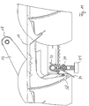
- a device 30 for restraining the step roller 18 from rising from the inner rail 24 to the outer rail 22, thus preventing it from colliding with the outer rail 22 in the turn around areas at the top and bottom of the escalator is mounted to the support or connecting arm 16 and will be described in detail hereinafter with reference to Figs. 4a and 4b .
- the device 30 for restraining the rise of the step roller 18 comprises: a supplementary roller 50, which is in contact with the outer rail 22 of the track 20; an elastic member 40 for biasing the supplementary roller 50 toward the outer rail 22; and a supporting block 32, which is attached to the support arm 16 to support the elastic member 40.
- the elastic member 40 is a linear spring, which is configured to have a first leg 42 and a second leg 44 that are bent with respect to each other by a predetermined angle in a A shape.
- the supporting block 32 has first and second recesses 34 and 36 on its front surface, in which the first and second legs 42 and 44 of the elastic member 40 are seated, respectively.
- the first recess 34 extends downward from the top end of the supporting block 32 by a specific length.
- the second recess 36 extends downward from the top end of the supporting block 32 to the bottom end thereof. These recesses 34 and 36 are slanted at a predetermined angle toward the step roller 18.
- the first leg 42 of the elastic member 40 is provided with a bent portion 42a at its tip.
- the bent portion 42a of the first leg 42 is pivotably inserted into an insertion hole 35, which is formed at an end of the first recess 34 of the supporting block 32.
- the second leg 44 of the elastic member 40 is provided with a first bent portion 44a and a second bent portion 44b at its tip.
- the first bent portion 44a extends rearward of the supporting block 32 and is in contact with the bottom surface of the supporting block 32.
- the second bent portion 44b extends from the end of the first bent portion 44a and is in contact with the bottom surface of the supporting block 32 so as to serve as a base point of the elastic member 40.
- the first and second recesses 34 and 36 of the supporting block 32 are a little wider than the first and second legs 42 and 44 of the elastic member 40. This is so that the elastic member 40 can be deformed within a limited range, which will be described later.
- a cover 38 is coupled to the front surface of the supporting block 32 by a fastening means, such as a bolt 39. This is to cover the first and second recesses 34 and 36 and prevent the first and second legs 42 and 44 of the elastic member 40 from being separated therefrom.
- the elastic member 40 is coupled to a supplementary roller-supporting member 52 at a portion adjacent to the junction between the first and second legs 42 and 44.
- Receiving slots 53 are formed at the rear surface of the supporting member 52, in which the first and second legs 42 and 44 of the elastic member 40 are seated.
- a cover 54 is attached to the rear surface of the supporting member 52 by a fastening means, such as a bolt 55. This is to prevent the legs 42 and 44 of the elastic member 40 from being separated from the receiving slots 53.
- the step roller 18 moves along the linear portion of the track 20 at the passenger conveying area, the step roller 18 rolls on the inner rail 24 of the track 20. Further, the supplementary roller 50 is biased toward the outer rail 22 of the track 20 by the elastic member 40 and rolls on the outer rail 22.
- the second leg 44 moves within the second recess 36 with the first and second bent portions 44a and 44b contacting the bottom surface of the supporting block 32.
- the restoring force against the force acting on the step roller 18 and the elastic member 40 is generated between the second bent portion 44b of the second leg 44 of the elastic member 40 and the supporting block 32.
- the step roller 18 stops rising and returns to its original position (i.e., onto the inner rail 24 of the track 20). Accordingly, the step roller 18 is restrained from colliding with the outer rail 22 of the track 20.
- the collision of the step roller 18 with the outer rail 22 of the track 20 at the turn around area may be completely restrained as the present embodiment, or may occur so rarely that there is very little shock.
- Figures 6 to 12 show a second embodiment of the present invention, the general construction of the respective people conveyor 2 is similar to that of the first embodiment.
- the step 10 has a treat surface 56 and a step riser 58.
- the step riser 58 is partially broken away in order to allow view to the restraining device 30 which is placed in this area.
- step 10 is rotatably attached at connection 60 to step chain 12.
- a support arm 16 carrying the step roller 18 is attached via flange 62 to step 10.
- the step chain 12 comprises a plurality of chain links 64 which are attached serially one after the other at joints 66.
- Step chain roller 68 are also attached to the corresponding joints 66.
- step rollers 18 are guided in a step roller track 20, a separate chain roller track is provided for guiding the chain rollers 68.
- WO 02/44069 A1 entitled CHAIN SEGMENT FOR PERSONAL CONVEYOR and filed by the same applicants as the present invention.
- Fig. 7 is similar to Fig. 6 with the main exception that the step 12 be removed. Particularly, Fig. 7 shows that two opposite chain links 64 are connected with each other by means of a connecting axle 70. Substantially midways between the two chain links 64 a bracket 72 is mounted to the connecting axle 70 for supporting a lateral guide roller 74. Attached to such bracket 72 are also two tortion springs 76 each having one free end 78 supported against the connecting axle 70. The second free end 80 is operationally engaged with the step riser 58 as can be seen in Figures 6 and 9 .
- Fig. 9 shows schematically a part of the endless path of the endless conveyor band 4 and particularly shows the steps 10 moving through a passenger conveying portion 6 or "inclined portion" with an escalator, through a transition portion 82, a turnaround portions 8, a further transition portion 84 and towards a return portion 5.
- the step rollers 18 are guided in the step roller track 20.
- Detail 8 in Fig. 10 clearly shows the second free end of portion spring 76 out of engagement from the step riser 58. Only during the passage through the first transition portion 82 the second free end 80 of torsion spring 76 comes in engagement with the riser 58 of step 10 as can be seen in detail C of Fig. 11 .
- step 10 As the step 10 is rotatably connected to the step chain 12 at the connection 60, the engagement of the free end 8 of torsion spring 6 tends to rotate the step 10 around connection 60 clockwise and tends to restrain roller 18 against the inner rail 22 of step roller track 20.
- This engagement of the second free end 80 with the step riser 58 continues throughout the turnaround portion 3 and thus keeps the step roller 18 in engagement with the inner rail 22.
- the torsion spring 76 may keep the step roller 13 in engagement with the inner rail 22 until the engagement of the free ends 30 with the riser 56 terminates in the second transition portion 34 and allows for a gradual changeover to the outer rail 24 in this area.
- the gravity load of the step 12 exceeds the force of torsion springs 76 in the course of moving through the turnaround portion 3 and allows for a smooth transition from the inner rail 22 to the outer rail 24 already in this area.
- the free ends 30 of torsion springs 76 are out of engagement with the step riser 58 so that the gravity load of the step 10 ensures engagement of the step roller 18 with the outer rail 24 in this portion.
- At least one restrain device 30 is provided with each step 10 of the step band.
- a device can restrain a step roller from rising toward an outer rail of a track at turn around areas of an escalator by a supplementary roller biased toward the outer rail of the track by an elastic member. This can prevent the shock and noise caused by the collision, thus providing the passengers with comfort and stability.
Landscapes
- Escalators And Moving Walkways (AREA)
- Rollers For Roller Conveyors For Transfer (AREA)
Claims (13)
- Personenbeförderungseinrichtung (2) beinhaltend ein endloses Beförderungseinrichtungsband (4), das sich durch einen schrägen Bereich (6), einen ersten und einen zweiten Umkehrbereich (8) und einen Rückführbereich (5) eines endlosen Weges erstreckt, und umfassend eine Mehrzahl von Stufen (10), die verbunden sind mit und angetrieben werden von einer Stufenkette (12), wobei die Stufen (10) eine Stufenrolle (18) umfassen, die durch einen Verbindungsarm (16) an der Stufe angebracht ist, wobei die Personenbeförderungseinrichtung (2) des Weiteren eine Verbindungsachse (70), die ein Kettenglied (64) an einer Seite des Beförderungseinrichtungsbands (4) mit einem Kettenglied (64) auf der anderen Seite des Beförderungseinrichtungsbands (4) verbindet, und eine Stufenrollenführung (20) zum Führen der Stufenrolle (18) beinhaltet, wobei sich die Stufenrollenführung (20) entlang des Weges des Beförderungseinrichtungsbands (4) erstreckt und eine innere und eine äußere Schiene (24, 22) zum Aufnehmen der Stufenrolle (18) und eine Vorrichtung (30) aufweist zum Abstützen der Stufenrolle (18) gegen eine von der inneren und der äußeren Schiene (24, 22), wobei die Abstützvorrichtung (30) an der Verbindungsachse (70) im Wesentlichen mittig zwischen den beiden Kettengliedern (64) angebracht ist.
- Personenbeförderungseinrichtung (2) nach Anspruch 1, wobei die Abstützvorrichtung (30) ein elastisches Beaufschlagungselement (40) umfasst zum elastischen Beaufschlagen der Stufenrolle (18) gegen eine der inneren und der äußeren Schiene (24, 22).
- Personenbeförderungseinrichtung (2) nach Anspruch 1 oder 2, wobei die Abstützvorrichtung (30) dazu ausgebildet ist, dass sie einen schrittweisen Übergang der Stufenrolle (18) von einer der inneren und der äußeren Schiene (24, 22) zu der anderen der inneren und der äußeren Schiene (24, 22) in jedem des ersten und des zweiten Umkehrbereichs (8) erlaubt.
- Personenbeförderungseinrichtung (2) nach einem der Ansprüche 1 bis 3, wobei die Abstützvorrichtung (30) zwischen der Stufe (10) und der Antriebskette (12) angeordnet ist.
- Personenbeförderungseinrichtung (2) nach einem der Ansprüche 1 bis 3, wobei eine Antriebskette (12) an jeder seitlichen Kante des Beförderungseinrichtungsbands (4) angeordnet ist, wobei jede Stufenkette (12) eine Mehrzahl von Kettengliedern (64) beinhaltet, und wobei eine Verbindungsachse (70) ein Kettenglied (64) an einer Seite des Beförderungseinrichtungsbands (4) mit einem Kettenglied (64) auf der anderen Seite des Beförderungseinrichtungsbands (4) verbindet, und wobei die Abstützvorrichtung (30) zwischen der Stufe (10) und der Verbindungsachse (70) angeordnet ist.
- Personenbeförderungseinrichtung (2) nach Anspruch 5, wobei die Abstützungsvorrichtung (30) eine Torsionsfeder (76), die an der Verbindungsachse (70) angebracht ist und an derselben mit einem der freien Enden (78) dieser Feder (76) gehalten ist und das zweite freie Ende (80) davon derart angeordnet ist, dass es mit der Stufe (10) zusammenwirkt.
- Personenbeförderungseinrichtung (2) nach einem der Ansprüche 1 bis 3, wobei die Abstützvorrichtung (30) zwischen der Stufe (10) und der Stufenrollenführung (20) angeordnet ist.
- Personenbeförderungseinrichtung (2) nach Anspruch 7, wobei die Abstützvorrichtung (30) eine zusätzliche Rolle (50) und ein Beaufschlagungsmittel (40) umfasst zum Beaufschlagen der zusätzlichen Rolle (50) gegen eine Schiene (22, 24) der Stufenrollenführung (20).
- Personenbeförderungseinrichtung (2) nach Anspruch 8, wobei die Stufenrolle (18) mit der Stufe (10) durch den Verbindungsarm (16) verbunden ist, und wobei die zusätzliche Rolle (50) durch den Verbindungsarm (16) gehalten ist.
- Personenbeförderungseinrichtung (2) nach Anspruch 8 oder 9, wobei das Beaufschlagungsmittel (40) die zusätzliche Rolle (50) gegen die äußere Schiene (22) beaufschlagt.
- Personenbeförderungseinrichtung (2) nach einem der Ansprüche 8 bis 10, wobei das Beaufschlagungsmittel eine lineare Feder ist, die einen ersten Abschnitt (42) und einen zweiten Abschnitt (44) aufweist, die in einem vorbestimmten Winkel bezogen aufeinander gebogen sind, des Weiteren umfassend einen Stützblock (32) an dem Verbindungsarm (16), wobei der Stützblock (32) eine erste und eine zweite Aussparung (34, 36) aufweist, wobei jeder Bereich des ersten und des zweiten Abschnitts der linearen Feder jeweils in die erste und die zweite Aussparung (34, 36) eingepasst sind, um damit eine Verformung des ersten und des zweiten Abschnitts (42, 44) der linearen Feder auf einen vorbestimmten Bereich zu beschränken.
- Personenbeförderungseinrichtung (2) nach Anspruch 11, des Weiteren umfassend eine Abdeckung (38), die an dem Stützblock (32) angebracht ist, um den ersten und den zweiten Abschnitt (42, 44) der linearen Feder daran zu hindern, von der ersten und der zweiten Aussparung (34, 36) des Stützblocks (32) getrennt zu werden.
- Personenbeförderungseinrichtung (2) nach Anspruch 11 oder 12 des Weiteren umfassend ein Element (52) zum Stützen der zusätzlichen Rolle (50), wobei das Element (52) eine Aussparung (53) aufweist, in welcher ein Bereich benachbart zu der Verbindung zwischen dem ersten und dem zweiten Abschnitt (42, 44) der linearen Feder eingepasst ist, und eine Abdeckung (54), die die Aussparung (53) des Elements (52) abdeckt.
Applications Claiming Priority (2)
| Application Number | Priority Date | Filing Date | Title |
|---|---|---|---|
| KR10-2003-0085911A KR100522064B1 (ko) | 2003-11-29 | 2003-11-29 | 에스컬레이터의 스텝롤러 상승억제장치 |
| PCT/EP2004/013529 WO2005051831A1 (en) | 2003-11-29 | 2004-11-29 | Device for restraining the rise of a step roller of a people conveyor |
Publications (2)
| Publication Number | Publication Date |
|---|---|
| EP1704109A1 EP1704109A1 (de) | 2006-09-27 |
| EP1704109B1 true EP1704109B1 (de) | 2012-05-02 |
Family
ID=36676139
Family Applications (2)
| Application Number | Title | Priority Date | Filing Date |
|---|---|---|---|
| EP04808228A Expired - Lifetime EP1692069B1 (de) | 2003-11-29 | 2004-11-26 | Vorrichtung zum verhindern des anhebens einer stufenrolle einer rolltreppe |
| EP04803340A Expired - Lifetime EP1704109B1 (de) | 2003-11-29 | 2004-11-29 | Vorrichtung zur verhinderung des anhebens einer fahrstufenrolle einer personenförderanlage |
Family Applications Before (1)
| Application Number | Title | Priority Date | Filing Date |
|---|---|---|---|
| EP04808228A Expired - Lifetime EP1692069B1 (de) | 2003-11-29 | 2004-11-26 | Vorrichtung zum verhindern des anhebens einer stufenrolle einer rolltreppe |
Country Status (7)
| Country | Link |
|---|---|
| US (2) | US7401692B2 (de) |
| EP (2) | EP1692069B1 (de) |
| JP (2) | JP4427061B2 (de) |
| KR (2) | KR100522064B1 (de) |
| CN (2) | CN1886328B (de) |
| AT (1) | ATE556021T1 (de) |
| WO (2) | WO2005051830A1 (de) |
Families Citing this family (9)
| Publication number | Priority date | Publication date | Assignee | Title |
|---|---|---|---|---|
| KR20050108737A (ko) * | 2004-05-13 | 2005-11-17 | 오티스 엘리베이터 컴파니 | 승객수송장치의 충격 및 소음저감장치 |
| ES2334630B1 (es) * | 2009-07-17 | 2010-09-22 | Thyssenkrupp Elevator Innovation Center, S.A. | Escalera mecanica. |
| KR100974430B1 (ko) * | 2010-01-19 | 2010-08-05 | 이봉석 | 석탄용 폐컨베이어벨트의 회수장치 |
| WO2014016888A1 (ja) * | 2012-07-23 | 2014-01-30 | ジョンソン コントロールズ テクノロジー カンパニ- | 乗り物用シートスライド装置 |
| KR101396320B1 (ko) * | 2013-11-06 | 2014-05-16 | 수림엘리베이터(주) | 에스컬레이터의 스텝용 체인롤러 및 스텝롤러의 레일 및 가이드장치 |
| US9560853B2 (en) * | 2014-12-23 | 2017-02-07 | Aleksandr Taslagyan | Return flow conveyor device for heating food items |
| EP3851403B1 (de) * | 2020-01-15 | 2022-09-28 | Otis Elevator Company | Stützelement für einen antriebsriemen eines personenförderers |
| CN117755729A (zh) * | 2022-09-16 | 2024-03-26 | 苏州飞格立工程塑料有限公司 | 带有滑动元件的输送器件 |
| KR102782831B1 (ko) | 2022-12-20 | 2025-03-14 | 주식회사 포스코지와이에스테크 | 폐 벨트 권취장치 |
Family Cites Families (27)
| Publication number | Priority date | Publication date | Assignee | Title |
|---|---|---|---|---|
| GB191016267A (en) | 1910-07-07 | 1911-03-30 | Victor Trevett | Improvements in Devices for Silencing or Preventing Rattling of Window Sashes. |
| GB203033A (en) | 1922-05-29 | 1923-08-29 | William Sebastian Graff Baker | Improvements in escalators |
| GB492715A (en) | 1937-03-23 | 1938-09-23 | J & E Hall Ltd | Improvements relating to escalators and like apparatus |
| GB491301A (en) * | 1937-05-20 | 1938-08-30 | Waygood Otis Ltd | Improvements in and relating to moving stairways |
| GB549616A (en) | 1940-06-18 | 1942-11-30 | Westinghouse Electric Int Co | Improvements in or relating to moving stairways |
| JPS5281885A (en) * | 1975-12-29 | 1977-07-08 | Hitachi Ltd | Structure for preventing steps from floating |
| JPS6052487A (ja) * | 1983-08-30 | 1985-03-25 | 三菱電機株式会社 | エスカレ−タ装置 |
| JPS60223782A (ja) | 1984-04-19 | 1985-11-08 | 三菱電機株式会社 | エスカレ−タ装置 |
| CH664548A5 (de) * | 1984-08-22 | 1988-03-15 | Inventio Ag | Stufe einer fahrtreppe. |
| DE3663933D1 (en) * | 1985-08-06 | 1989-07-20 | Inventio Ag | Moving-stairs with raising sides |
| EP0443039B1 (de) * | 1989-09-07 | 1996-08-14 | Masao Kubota | Beförderungsmaschine |
| JPH0420495A (ja) * | 1990-05-14 | 1992-01-24 | Toshiba Corp | エスカレータの踏段異常検知装置 |
| US5161668A (en) * | 1991-07-18 | 1992-11-10 | Montgomery Electric Company | Guide mechanism for passenger conveyors |
| JP2768223B2 (ja) * | 1993-01-13 | 1998-06-25 | フジテック株式会社 | エスカレータ装置 |
| JP2663826B2 (ja) * | 1993-02-09 | 1997-10-15 | フジテック株式会社 | エスカレータ装置 |
| JPH06321473A (ja) * | 1993-05-17 | 1994-11-22 | Toshiba Corp | 動く歩道 |
| JPH074475U (ja) * | 1993-06-24 | 1995-01-24 | オーチス エレベータ カンパニー | エスカレーターのステップ |
| US5487449A (en) | 1994-04-06 | 1996-01-30 | Otis Elevator Company | Magnetic elevator door coupling |
| JP3866341B2 (ja) * | 1996-11-05 | 2007-01-10 | 三菱電機株式会社 | 車椅子踏段付エスカレーターの運転方法及び車椅子踏段付エスカレーター |
| JP4303840B2 (ja) * | 1999-07-16 | 2009-07-29 | 東芝エレベータ株式会社 | 乗客コンベヤ装置 |
| JP4688276B2 (ja) | 2000-11-09 | 2011-05-25 | 東芝エレベータ株式会社 | 乗客コンベア装置 |
| US6450316B1 (en) * | 2000-11-28 | 2002-09-17 | Otis Elevator Company | Escalator with step flange |
| JP4810030B2 (ja) * | 2001-09-26 | 2011-11-09 | 三菱電機株式会社 | 傾斜部高速エスカレータ |
| US6685003B2 (en) * | 2001-12-28 | 2004-02-03 | Otis Elevator Company | Pulse-free escalator |
| JP4187971B2 (ja) * | 2002-01-21 | 2008-11-26 | 三菱電機株式会社 | 傾斜部高速エスカレーター |
| US7124875B2 (en) * | 2002-01-23 | 2006-10-24 | Mitsubishi Denki Kabushiki Kaisha | Escalator with high speed inclined section |
| DE60313504T2 (de) * | 2003-02-07 | 2008-01-03 | Otis Elevator Co., Farmington | Seitliche halteeinrichtung für personenförderband |
-
2003
- 2003-11-29 KR KR10-2003-0085911A patent/KR100522064B1/ko not_active Expired - Fee Related
-
2004
- 2004-11-26 EP EP04808228A patent/EP1692069B1/de not_active Expired - Lifetime
- 2004-11-26 JP JP2006541040A patent/JP4427061B2/ja not_active Expired - Fee Related
- 2004-11-26 US US10/579,003 patent/US7401692B2/en not_active Expired - Fee Related
- 2004-11-26 WO PCT/KR2004/003077 patent/WO2005051830A1/en not_active Ceased
- 2004-11-26 CN CN2004800352240A patent/CN1886328B/zh not_active Expired - Fee Related
- 2004-11-29 AT AT04803340T patent/ATE556021T1/de active
- 2004-11-29 US US10/579,005 patent/US7357241B2/en not_active Expired - Fee Related
- 2004-11-29 KR KR1020067010285A patent/KR100826720B1/ko not_active Expired - Fee Related
- 2004-11-29 JP JP2006540405A patent/JP4500816B2/ja not_active Expired - Fee Related
- 2004-11-29 EP EP04803340A patent/EP1704109B1/de not_active Expired - Lifetime
- 2004-11-29 CN CN2004800411484A patent/CN1906114B/zh not_active Expired - Fee Related
- 2004-11-29 WO PCT/EP2004/013529 patent/WO2005051831A1/en not_active Ceased
Also Published As
| Publication number | Publication date |
|---|---|
| HK1099545A1 (zh) | 2007-08-17 |
| EP1692069A1 (de) | 2006-08-23 |
| KR100826720B1 (ko) | 2008-05-02 |
| CN1906114B (zh) | 2010-04-28 |
| KR20060103438A (ko) | 2006-09-29 |
| US7401692B2 (en) | 2008-07-22 |
| WO2005051830A1 (en) | 2005-06-09 |
| CN1906114A (zh) | 2007-01-31 |
| EP1692069A4 (de) | 2012-05-09 |
| US20070144866A1 (en) | 2007-06-28 |
| KR100522064B1 (ko) | 2005-10-18 |
| CN1886328A (zh) | 2006-12-27 |
| JP4500816B2 (ja) | 2010-07-14 |
| JP2007512205A (ja) | 2007-05-17 |
| JP2007533570A (ja) | 2007-11-22 |
| EP1692069B1 (de) | 2013-02-20 |
| CN1886328B (zh) | 2010-05-05 |
| HK1103581A1 (zh) | 2007-12-21 |
| US20070051584A1 (en) | 2007-03-08 |
| JP4427061B2 (ja) | 2010-03-03 |
| EP1704109A1 (de) | 2006-09-27 |
| ATE556021T1 (de) | 2012-05-15 |
| WO2005051831A1 (en) | 2005-06-09 |
| US7357241B2 (en) | 2008-04-15 |
| KR20050052072A (ko) | 2005-06-02 |
Similar Documents
| Publication | Publication Date | Title |
|---|---|---|
| US4064986A (en) | Escalator having guide wheels and guide track with cooperative non-flat surfaces | |
| CN107298370B (zh) | 板式传送装置 | |
| US7357241B2 (en) | Device for restraining the rise of a step roller of a people conveyor | |
| CN101428727B (zh) | 自动人行道 | |
| EP0141519B1 (de) | Rolltreppe mit bogenförmiger Strecke | |
| EP0087692B1 (de) | Rolltreppenstufe | |
| US5899314A (en) | Terminal rail for passenger conveyor | |
| JPH07157260A (ja) | エスカレータおよびそのステップチェーン支持装置 | |
| WO2010074669A1 (en) | Moving skirt mechanism for chain driven passenger conveyors | |
| EP2570378B1 (de) | Bidirektional beweglicher Fahrsteig | |
| US20080087522A1 (en) | Shock Absorbing Device For Passenger Conveyors | |
| HK1103581B (en) | Device for restraining the rise of a step roller of a people conveyor | |
| JP5752762B2 (ja) | 乗客コンベア | |
| HK1099545B (en) | Device for restraining the rise of a step roller of an escalator | |
| WO2011033178A1 (en) | People mover | |
| WO1994026637A1 (en) | Transport device with load carriers for the transport of goods | |
| CN107618968B (zh) | 人输送机的运输元件 | |
| JP2008156018A (ja) | エスカレータの踏段浮き上がり防止装置 | |
| HK1105941B (en) | Shock absorbing device for passenger conveyors |
Legal Events
| Date | Code | Title | Description |
|---|---|---|---|
| PUAI | Public reference made under article 153(3) epc to a published international application that has entered the european phase |
Free format text: ORIGINAL CODE: 0009012 |
|
| 17P | Request for examination filed |
Effective date: 20060619 |
|
| AK | Designated contracting states |
Kind code of ref document: A1 Designated state(s): AT BE BG CH CY CZ DE DK EE ES FI FR GB GR HU IE IS IT LI LU MC NL PL PT RO SE SI SK TR |
|
| DAX | Request for extension of the european patent (deleted) | ||
| GRAP | Despatch of communication of intention to grant a patent |
Free format text: ORIGINAL CODE: EPIDOSNIGR1 |
|
| GRAS | Grant fee paid |
Free format text: ORIGINAL CODE: EPIDOSNIGR3 |
|
| GRAA | (expected) grant |
Free format text: ORIGINAL CODE: 0009210 |
|
| AK | Designated contracting states |
Kind code of ref document: B1 Designated state(s): AT BE BG CH CY CZ DE DK EE ES FI FR GB GR HU IE IS IT LI LU MC NL PL PT RO SE SI SK TR |
|
| REG | Reference to a national code |
Ref country code: GB Ref legal event code: FG4D |
|
| REG | Reference to a national code |
Ref country code: AT Ref legal event code: REF Ref document number: 556021 Country of ref document: AT Kind code of ref document: T Effective date: 20120515 Ref country code: CH Ref legal event code: EP |
|
| REG | Reference to a national code |
Ref country code: IE Ref legal event code: FG4D |
|
| REG | Reference to a national code |
Ref country code: DE Ref legal event code: R096 Ref document number: 602004037666 Country of ref document: DE Effective date: 20120628 |
|
| REG | Reference to a national code |
Ref country code: NL Ref legal event code: VDEP Effective date: 20120502 |
|
| PG25 | Lapsed in a contracting state [announced via postgrant information from national office to epo] |
Ref country code: IS Free format text: LAPSE BECAUSE OF FAILURE TO SUBMIT A TRANSLATION OF THE DESCRIPTION OR TO PAY THE FEE WITHIN THE PRESCRIBED TIME-LIMIT Effective date: 20120902 Ref country code: PL Free format text: LAPSE BECAUSE OF FAILURE TO SUBMIT A TRANSLATION OF THE DESCRIPTION OR TO PAY THE FEE WITHIN THE PRESCRIBED TIME-LIMIT Effective date: 20120502 Ref country code: FI Free format text: LAPSE BECAUSE OF FAILURE TO SUBMIT A TRANSLATION OF THE DESCRIPTION OR TO PAY THE FEE WITHIN THE PRESCRIBED TIME-LIMIT Effective date: 20120502 Ref country code: CY Free format text: LAPSE BECAUSE OF FAILURE TO SUBMIT A TRANSLATION OF THE DESCRIPTION OR TO PAY THE FEE WITHIN THE PRESCRIBED TIME-LIMIT Effective date: 20120502 Ref country code: SE Free format text: LAPSE BECAUSE OF FAILURE TO SUBMIT A TRANSLATION OF THE DESCRIPTION OR TO PAY THE FEE WITHIN THE PRESCRIBED TIME-LIMIT Effective date: 20120502 |
|
| REG | Reference to a national code |
Ref country code: AT Ref legal event code: MK05 Ref document number: 556021 Country of ref document: AT Kind code of ref document: T Effective date: 20120502 |
|
| PG25 | Lapsed in a contracting state [announced via postgrant information from national office to epo] |
Ref country code: GR Free format text: LAPSE BECAUSE OF FAILURE TO SUBMIT A TRANSLATION OF THE DESCRIPTION OR TO PAY THE FEE WITHIN THE PRESCRIBED TIME-LIMIT Effective date: 20120803 Ref country code: SI Free format text: LAPSE BECAUSE OF FAILURE TO SUBMIT A TRANSLATION OF THE DESCRIPTION OR TO PAY THE FEE WITHIN THE PRESCRIBED TIME-LIMIT Effective date: 20120502 Ref country code: PT Free format text: LAPSE BECAUSE OF FAILURE TO SUBMIT A TRANSLATION OF THE DESCRIPTION OR TO PAY THE FEE WITHIN THE PRESCRIBED TIME-LIMIT Effective date: 20120903 |
|
| PG25 | Lapsed in a contracting state [announced via postgrant information from national office to epo] |
Ref country code: BE Free format text: LAPSE BECAUSE OF FAILURE TO SUBMIT A TRANSLATION OF THE DESCRIPTION OR TO PAY THE FEE WITHIN THE PRESCRIBED TIME-LIMIT Effective date: 20120502 |
|
| PG25 | Lapsed in a contracting state [announced via postgrant information from national office to epo] |
Ref country code: CZ Free format text: LAPSE BECAUSE OF FAILURE TO SUBMIT A TRANSLATION OF THE DESCRIPTION OR TO PAY THE FEE WITHIN THE PRESCRIBED TIME-LIMIT Effective date: 20120502 Ref country code: NL Free format text: LAPSE BECAUSE OF FAILURE TO SUBMIT A TRANSLATION OF THE DESCRIPTION OR TO PAY THE FEE WITHIN THE PRESCRIBED TIME-LIMIT Effective date: 20120502 Ref country code: DK Free format text: LAPSE BECAUSE OF FAILURE TO SUBMIT A TRANSLATION OF THE DESCRIPTION OR TO PAY THE FEE WITHIN THE PRESCRIBED TIME-LIMIT Effective date: 20120502 Ref country code: AT Free format text: LAPSE BECAUSE OF FAILURE TO SUBMIT A TRANSLATION OF THE DESCRIPTION OR TO PAY THE FEE WITHIN THE PRESCRIBED TIME-LIMIT Effective date: 20120502 Ref country code: EE Free format text: LAPSE BECAUSE OF FAILURE TO SUBMIT A TRANSLATION OF THE DESCRIPTION OR TO PAY THE FEE WITHIN THE PRESCRIBED TIME-LIMIT Effective date: 20120502 Ref country code: RO Free format text: LAPSE BECAUSE OF FAILURE TO SUBMIT A TRANSLATION OF THE DESCRIPTION OR TO PAY THE FEE WITHIN THE PRESCRIBED TIME-LIMIT Effective date: 20120502 Ref country code: SK Free format text: LAPSE BECAUSE OF FAILURE TO SUBMIT A TRANSLATION OF THE DESCRIPTION OR TO PAY THE FEE WITHIN THE PRESCRIBED TIME-LIMIT Effective date: 20120502 |
|
| PG25 | Lapsed in a contracting state [announced via postgrant information from national office to epo] |
Ref country code: IT Free format text: LAPSE BECAUSE OF FAILURE TO SUBMIT A TRANSLATION OF THE DESCRIPTION OR TO PAY THE FEE WITHIN THE PRESCRIBED TIME-LIMIT Effective date: 20120502 |
|
| PLBE | No opposition filed within time limit |
Free format text: ORIGINAL CODE: 0009261 |
|
| STAA | Information on the status of an ep patent application or granted ep patent |
Free format text: STATUS: NO OPPOSITION FILED WITHIN TIME LIMIT |
|
| 26N | No opposition filed |
Effective date: 20130205 |
|
| PG25 | Lapsed in a contracting state [announced via postgrant information from national office to epo] |
Ref country code: ES Free format text: LAPSE BECAUSE OF FAILURE TO SUBMIT A TRANSLATION OF THE DESCRIPTION OR TO PAY THE FEE WITHIN THE PRESCRIBED TIME-LIMIT Effective date: 20120813 |
|
| REG | Reference to a national code |
Ref country code: DE Ref legal event code: R097 Ref document number: 602004037666 Country of ref document: DE Effective date: 20130205 |
|
| REG | Reference to a national code |
Ref country code: CH Ref legal event code: PL |
|
| GBPC | Gb: european patent ceased through non-payment of renewal fee |
Effective date: 20121129 |
|
| PG25 | Lapsed in a contracting state [announced via postgrant information from national office to epo] |
Ref country code: LI Free format text: LAPSE BECAUSE OF NON-PAYMENT OF DUE FEES Effective date: 20121130 Ref country code: BG Free format text: LAPSE BECAUSE OF FAILURE TO SUBMIT A TRANSLATION OF THE DESCRIPTION OR TO PAY THE FEE WITHIN THE PRESCRIBED TIME-LIMIT Effective date: 20120802 Ref country code: CH Free format text: LAPSE BECAUSE OF NON-PAYMENT OF DUE FEES Effective date: 20121130 |
|
| REG | Reference to a national code |
Ref country code: FR Ref legal event code: ST Effective date: 20130731 |
|
| REG | Reference to a national code |
Ref country code: IE Ref legal event code: MM4A |
|
| PG25 | Lapsed in a contracting state [announced via postgrant information from national office to epo] |
Ref country code: IE Free format text: LAPSE BECAUSE OF NON-PAYMENT OF DUE FEES Effective date: 20121129 |
|
| PG25 | Lapsed in a contracting state [announced via postgrant information from national office to epo] |
Ref country code: GB Free format text: LAPSE BECAUSE OF NON-PAYMENT OF DUE FEES Effective date: 20121129 Ref country code: FR Free format text: LAPSE BECAUSE OF NON-PAYMENT OF DUE FEES Effective date: 20121130 |
|
| PGFP | Annual fee paid to national office [announced via postgrant information from national office to epo] |
Ref country code: DE Payment date: 20131127 Year of fee payment: 10 |
|
| PG25 | Lapsed in a contracting state [announced via postgrant information from national office to epo] |
Ref country code: MC Free format text: LAPSE BECAUSE OF NON-PAYMENT OF DUE FEES Effective date: 20121130 Ref country code: TR Free format text: LAPSE BECAUSE OF FAILURE TO SUBMIT A TRANSLATION OF THE DESCRIPTION OR TO PAY THE FEE WITHIN THE PRESCRIBED TIME-LIMIT Effective date: 20120502 |
|
| PG25 | Lapsed in a contracting state [announced via postgrant information from national office to epo] |
Ref country code: LU Free format text: LAPSE BECAUSE OF NON-PAYMENT OF DUE FEES Effective date: 20121129 |
|
| PG25 | Lapsed in a contracting state [announced via postgrant information from national office to epo] |
Ref country code: HU Free format text: LAPSE BECAUSE OF FAILURE TO SUBMIT A TRANSLATION OF THE DESCRIPTION OR TO PAY THE FEE WITHIN THE PRESCRIBED TIME-LIMIT Effective date: 20041129 |
|
| REG | Reference to a national code |
Ref country code: DE Ref legal event code: R119 Ref document number: 602004037666 Country of ref document: DE |
|
| PG25 | Lapsed in a contracting state [announced via postgrant information from national office to epo] |
Ref country code: DE Free format text: LAPSE BECAUSE OF NON-PAYMENT OF DUE FEES Effective date: 20150602 |