EP1707106A2 - Elektronisches Endoskop - Google Patents
Elektronisches Endoskop Download PDFInfo
- Publication number
- EP1707106A2 EP1707106A2 EP06006426A EP06006426A EP1707106A2 EP 1707106 A2 EP1707106 A2 EP 1707106A2 EP 06006426 A EP06006426 A EP 06006426A EP 06006426 A EP06006426 A EP 06006426A EP 1707106 A2 EP1707106 A2 EP 1707106A2
- Authority
- EP
- European Patent Office
- Prior art keywords
- channel
- electronic endoscope
- detection section
- frequency band
- channel detection
- Prior art date
- Legal status (The legal status is an assumption and is not a legal conclusion. Google has not performed a legal analysis and makes no representation as to the accuracy of the status listed.)
- Granted
Links
- 238000001514 detection method Methods 0.000 claims abstract description 97
- 230000005540 biological transmission Effects 0.000 claims abstract description 40
- XLYOFNOQVPJJNP-UHFFFAOYSA-N water Substances O XLYOFNOQVPJJNP-UHFFFAOYSA-N 0.000 description 7
- 238000003780 insertion Methods 0.000 description 6
- 230000037431 insertion Effects 0.000 description 6
- 238000000926 separation method Methods 0.000 description 5
- 230000000875 corresponding effect Effects 0.000 description 4
- 238000010586 diagram Methods 0.000 description 4
- 238000012327 Endoscopic diagnosis Methods 0.000 description 3
- 238000005192 partition Methods 0.000 description 3
- 230000003321 amplification Effects 0.000 description 2
- 238000006243 chemical reaction Methods 0.000 description 2
- 230000001276 controlling effect Effects 0.000 description 2
- 230000002596 correlated effect Effects 0.000 description 2
- 238000005286 illumination Methods 0.000 description 2
- 238000000034 method Methods 0.000 description 2
- 238000012986 modification Methods 0.000 description 2
- 230000004048 modification Effects 0.000 description 2
- 238000003199 nucleic acid amplification method Methods 0.000 description 2
- 238000005070 sampling Methods 0.000 description 2
- 230000008054 signal transmission Effects 0.000 description 2
- 238000003384 imaging method Methods 0.000 description 1
- 239000007787 solid Substances 0.000 description 1
- 238000005406 washing Methods 0.000 description 1
Images


Classifications
-
- H—ELECTRICITY
- H04—ELECTRIC COMMUNICATION TECHNIQUE
- H04N—PICTORIAL COMMUNICATION, e.g. TELEVISION
- H04N7/00—Television systems
- H04N7/18—Closed-circuit television [CCTV] systems, i.e. systems in which the video signal is not broadcast
- H04N7/183—Closed-circuit television [CCTV] systems, i.e. systems in which the video signal is not broadcast for receiving images from a single remote source
- H04N7/185—Closed-circuit television [CCTV] systems, i.e. systems in which the video signal is not broadcast for receiving images from a single remote source from a mobile camera, e.g. for remote control
-
- A—HUMAN NECESSITIES
- A61—MEDICAL OR VETERINARY SCIENCE; HYGIENE
- A61B—DIAGNOSIS; SURGERY; IDENTIFICATION
- A61B1/00—Instruments for performing medical examinations of the interior of cavities or tubes of the body by visual or photographical inspection, e.g. endoscopes; Illuminating arrangements therefor
- A61B1/00002—Operational features of endoscopes
- A61B1/00011—Operational features of endoscopes characterised by signal transmission
- A61B1/00016—Operational features of endoscopes characterised by signal transmission using wireless means
-
- A—HUMAN NECESSITIES
- A61—MEDICAL OR VETERINARY SCIENCE; HYGIENE
- A61B—DIAGNOSIS; SURGERY; IDENTIFICATION
- A61B1/00—Instruments for performing medical examinations of the interior of cavities or tubes of the body by visual or photographical inspection, e.g. endoscopes; Illuminating arrangements therefor
- A61B1/00002—Operational features of endoscopes
- A61B1/00059—Operational features of endoscopes provided with identification means for the endoscope
-
- A—HUMAN NECESSITIES
- A61—MEDICAL OR VETERINARY SCIENCE; HYGIENE
- A61B—DIAGNOSIS; SURGERY; IDENTIFICATION
- A61B5/00—Measuring for diagnostic purposes; Identification of persons
- A61B5/0002—Remote monitoring of patients using telemetry, e.g. transmission of vital signals via a communication network
-
- A—HUMAN NECESSITIES
- A61—MEDICAL OR VETERINARY SCIENCE; HYGIENE
- A61B—DIAGNOSIS; SURGERY; IDENTIFICATION
- A61B1/00—Instruments for performing medical examinations of the interior of cavities or tubes of the body by visual or photographical inspection, e.g. endoscopes; Illuminating arrangements therefor
- A61B1/00064—Constructional details of the endoscope body
- A61B1/00108—Constructional details of the endoscope body characterised by self-sufficient functionality for stand-alone use
-
- H—ELECTRICITY
- H04—ELECTRIC COMMUNICATION TECHNIQUE
- H04W—WIRELESS COMMUNICATION NETWORKS
- H04W74/00—Wireless channel access
- H04W74/08—Non-scheduled access, e.g. ALOHA
Definitions
- the present invention relates to an electronic endoscope apparatus constituted of an electronic endoscope and a processor between which a signal is transmitted and received via radio waves.
- an imaging sensor such as a CCD is incorporated in a front end portion of an insertion section for being inserted into a body cavity.
- Image signals obtained by the CCD is subject to signal processing in a processor to observe an image of the body cavity, that is, an endoscopic image, on a monitor.
- the conventional electronic endoscope and the processor are connected through a signal cable.
- a wireless electronic endoscope apparatus is devised which transmits and receives the signals via radio waves without using the signal cable to improve operability of the electronic endoscope (see Japanese Patent Laid-Open Publication No. 2001-251612 ).
- a modulating section for modulating the signals and a transmitting section for transmitting the signals via the radio waves are provided in the electronic endoscope, and a receiving section for receiving the radio waves and a demodulating section for demodulating the radio waves into the original signals are provided in the processor.
- the conventional electronic endoscope with the signal cable requires approximately 4kV of a dielectric strength voltage between a patient circuit in the electronic endoscope and a secondary circuit in the processor.
- a dielectric strength voltage between a patient circuit in the electronic endoscope and a secondary circuit in the processor.
- high dielectric strength voltage is unnecessary in the wireless electronic endoscope apparatus since the signal cable is not used between the electronic endoscope and the processor.
- an endoscope examination room is separated into plural examination rooms by partitions, and the electronic endoscope apparatus is disposed in each of the examination rooms to perform the endoscopic diagnoses to plural patients at the same time.
- plural wireless electronic endoscope apparatuses it is necessary to avoid radio interference between the wireless electronic endoscope apparatuses.
- a frequency band allocated to the wireless signal transmission/reception between medical devices is limited to a certain range, the signals should be transmitted and received by a system corresponding to the above frequency band.
- the wireless electronic endoscope apparatus disclosed in the above reference uses a TV channel frequency band which is not the particular frequency band for the medical devices. Further, the above wireless electronic endoscope apparatus does not have a means to prevent the radio interference in the signal transmission/reception when plural wireless electronic endoscope apparatuses are used.
- a main object of the present invention is to provide an electronic endoscope apparatus capable of securely preventing radio interference between the electronic endoscope apparatuses.
- Another object of the invention is to provide an electronic endoscope apparatus having improved operability.
- an electronic endoscope apparatus of the present invention is constituted of an electronic endoscope, for obtaining an image of an observation area of a subject, and a processor.
- the electronic endoscope transmits data of the image to the processor via radio waves.
- the electronic endoscope includes a first channel detection section and a transmission frequency band switching section.
- the first channel detection section detects an available channel from plural channels previously allocated to each of plural transmission frequency bands of the radiowaves.
- the transmission frequency band switching section automatically switches between the transmission frequency bands according to a detection result of the first channel detection section.
- the processor includes a second channel detection section and a reception frequency band switching section.
- the second channel detection section detects an available channel from plural channels previously allocated to each of plural reception frequency bands of the radio waves.
- the reception frequency band switching section automatically switches between the reception frequency bands according to a detection result of the second channel detection section.
- the first channel detection section transmits a channel allocation request signal, for requesting allocation of the available channel, and a channel-in-use notification signal for notifying a currently used channel, to the second channel detection section via the radio waves.
- the second channel detection section transmits a channel number notification signal notifying the available channel, based on a detection result of channel usage condition, to the first channel detection section via the radio waves.
- the channel allocation request signal is transmitted immediately after the power of the electronic endoscope is turned on.
- the channel-in-use notification signal is transmitted at constant intervals.
- the channel allocation request signal, the channel-in-use notification signal and the channel number notification signal are transmitted and received through a different channel from those allocated to each of the transmission and reception frequency bands.
- the electronic endoscope includes the first channel detection section for detecting the available channel from the plural channels previously allocated to each of the plural transmission frequency bands.
- the processor includes the second channel detection section for detecting the available channel from the plural channels previously allocated to each of the plural reception frequency bands.
- the transmission frequency band switching section of the electronic endoscope automatically switches between the transmission frequency bands according to the detection result of the first channel detection section.
- the reception frequency band switching section automatically switches between the reception frequency bands according to the detection result of the second channel detection section. Accordingly, the radio interference between the electronic endoscope apparatuses is securely prevented. Further, since it is no longer necessary to manually set the channels and the frequency bands, the operability of the electronic endoscope apparatus is improved.
- an electronic endoscope apparatus 2 is constituted of an electronic endoscope 10 and a processor 11.
- the electronic endoscope 10 and the processor 11 of the electronic endoscope apparatus 2 transmit and receive signals via radio waves within a first or a second frequency bands (for instance, 1.2GHz or 2.4GHz). To each of the first and second frequency bands, plural channels are previously allocated.
- the electronic endoscope 10 is provided with an insertion section 13 inserted into a body cavity, and an operating section 14 connected to a base end portion of the insertion section 13.
- a front end section 13a at a front end portion of the insertion section 13 incorporates an objective lens 15 for taking in image light of an observation area in the body cavity, a CCD 16 which is an image sensor for capturing the image of the observation area in the body cavity, and an illumination lens 17 and an LED light source (hereinafter, an LED) 18 for illuminating the body cavity (see Fig. 2).
- the image of the body cavity taken by the CCD16 is displayed as an endoscopic image on a monitor 19 connected to the processor 11.
- a flexible section 20 formed of plural joint pieces .
- Awire extending through the insertion section 13 is pushed and pulled by operating an angle knob 14a provided in the operating section 14 to bend the flexible section 20 in the up, down, right and left directions.
- the front end section 13a can be directed toward a desired direction inside the body cavity.
- a cartridge 23 incorporating a water tank 21 and an air cylinder 22 is attached to a bottom portion of the operating section 14 in a removable manner. Water is stored in the water tank 21 and air is stored in the air cylinder 22.
- a water/air supply button 14b in the operating section 14 is operated, the water in the water tank 21 and the air in the air cylinder 22 are respectively supplied through a water pipe and an air pipe and ejected from a washing nozzle (not shown) formed in the front end section 13a to an objective lens 15. Thereby, dirt adhered to a surface of the objective lens 15 is removed and the air is supplied to the body cavity.
- a numeral 24 is a forceps opening into which a treatment tool is inserted.
- a CPU 30 controls overall operation of the electronic endoscope 10.
- the CPU 30 is connected to a ROM 31 which stores various programs and data for controlling the operation of the electronic endoscope 10.
- the CPU 30 reads necessary program and/or data from the ROM 31 to control the operation of the electronic endoscope 10.
- a driving section 32 is connected to the LED 18.
- the driving section 32 drives the LED 18 under control of the CPU 30.
- the light emitted from the LED 18 illuminates the observation area in the body cavity through the illumination lens 17.
- the CCD 16 focuses image light of the observation area entered through the objective lens 15 onto its image capture surface, and outputs the image signal corresponding to each pixel to an AFE 33.
- the AFE 33 performs correlated double sampling, amplification and A/D conversion to the image signal to convert the image signal into a digital image signal, and outputs the digital image signal to a modulating section 34.
- Themodulating section 34 performs, for instance, a digital quadrature modulation to the digital image signal to generate an RF signal.
- a transmitting section 35 transmits the RF signal to the processor 11 as a radio wave 12 within a first or a second frequency band through an antenna 36, which will be described later.
- a battery 38 is connected to a connector 37. Power of the battery 38 is supplied to each section of the electronic endoscope 10 through a power supply section 39 controlled by the CPU 30. Behind the operating section 14 , a battery chamber (not shown) is provided for accommodating the battery 38, and the connector 37 is disposed inside the battery chamber.
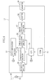
- a first frequency band transmission circuit 40 in the transmitting section 35 , a first frequency band transmission circuit 40, a second frequency band transmission circuit 41, a transmission frequency band switching circuit 42 and a first channel detection circuit 43 are provided.
- Each of the first and second frequency band transmission circuits 40, 41 is constituted of a power amplifier, an RF switch, and a circulator.
- the power amplifier amplifies the RF signal generated in the modulating section 34 to a level receivable by the processor 11.
- the RF-switch is turned on/off according to a timing of a burst in a TDMA (Time Division Multiple Access) method used in the electronic endoscope apparatus 2.
- the circulator supplies the RF signal as the radio wave 12 within the first or second frequency band to the antenna 36.
- the transmission frequency band switching circuit 42 is connected to a first frequency band transmission circuit 40 and asecondfrequency band transmission circuit 41.
- the transmission frequency band switching circuit 42 switches between the first and second frequency band transmission circuits 40, 41 according to a detection result of the first channel detection circuit 43.
- the second frequency band transmission circuit 41 is selected by the transmission frequency band switching circuit 42.
- the first channel detection circuit 43 transmits a channel allocation request signal Sa to a second channel detection circuit 63 (see FIG. 5) of the processor 11 for requesting a channel allocation. Further, the first channel detection circuit 43 transmits a channel-in-use notification signal Sb to the second channel detection circuit 63 to notify the allocated channel number currently used by the electronic endoscope 10. Further, the first channel detection circuit 43 receives a channel number notification signal Sc notifying an available channel number from the second channel detection circuit 63. The first channel detection circuit 43 transmits the notified available channel number to the CPU 30 and the transmission frequency band switching circuit 42.
- a CPU 50 controls overall operation of the processor 11.
- the CPU 50 is connected to a ROM 51 in which various programs and data for controlling the operation of the CPU 50 are stored.
- the CPU 50 reads the necessary program and data from the ROM 51 to control the operation of the processor 11.
- An antenna 52 receives the radio wave 12 from the electronic endoscope 10.
- a receiving section 53 amplifies the radio wave 12, that is, the RF signal received through the antenna 52.
- the demodulating section 54 demodulates the RF signal into the original image signal by, for instance, the digital quadrature detection.
- a synch-separation section 55 separates a synchronizing signal from the demodulated image signal by amplitude separation under the control of the CPU 50. Thereafter, a horizontal synchronizing signal and a vertical synchronizing signal are separated from the synchronizing signal by frequency separation.
- a video signal processing section 56 generates a digital video signal from the image signal.
- An image processing section 57 performs image processing such as mask generation and addition of character information to the digital video signal.
- a buffer 58 temporarily stores the digital video signal which will be displayed on the monitor 19 as the endoscopic image.
- a first frequency band reception circuit 60 in the receiving section 53 , a first frequency band reception circuit 60, a second frequency band reception circuit 61, a reception frequency band switching circuit 62 and the second channel detection circuit 63 are provided.
- Each of the first and second frequency band reception circuits 60, 61 is constituted of a circulator for supplying the radio waves received through the antenna 52, an RF switch, and a low-noise amplifier for amplifying the RF signals.
- the reception frequency band switching circuit 62 is connected to the first and second frequency band reception circuits 60, 61. According to the detection results of the second channel detection circuit 63, the reception frequency band switching circuit 62 automatically switches whether the first and second frequency band reception circuits 60, 61 to be used. In an initial setting, as with the electronic endoscope 10, the second frequency band reception circuit 61 is selected by the reception frequency band switching circuit 62.
- the second channel detection circuit 63 Upon receiving the channel allocation request signal Sa from the first channel detection circuit 43, the second channel detection circuit 63 transmits the channel number notification signal Sc to the first channel detection circuit 43 to notify the available channel number according to a channel usage condition notified by the channel-in-use notification signal (s) Sb from currently used endoscope (s) .
- the second channel detection circuit 63 transmits the channel number notification signal Sc to the CPU 50 and the reception frequency band switching circuit 62. When there is no available channel at the moment, the second channel detection circuit 63 does not transmit the channel number notification signal Sc.
- the above signals Sa to Sc are transmitted and received as the radio waves 12 between the first and second channel detection circuits 43, 63 through a different channel (0 channel) from those allocated to the first and second frequency bands.
- the channel-in-use notification signal Sb is transmitted from the first channel detection circuit 43 at constant intervals.
- the insertion section 13 is inserted into the body cavity and the LED 18 is turned on to illuminate the body cavity.
- the endoscopic image obtained by the CCD 16 is observed on the monitor 19.
- the image light of the observation area in the body cavity entered through the objective lens 15 is focused on the image capture surface of the CCD 16, and thereby the image signal is output from the CCD 16 to the AFE 33 .
- the correlated double sampling, the amplification and the A/D conversion are performed to the image signal to convert the image signal into the digital image signal.
- the digital quadrature modulation is performed to the digital image signal output from the AFE 33 to generate the RF signal.
- the RF signal is amplified in the transmitting section 35 and transmitted to the processor 11 as the radio wave 12 through the antenna 36 of the electronic endoscope 10.
- the processor 11 When the processor 11 receives the radio wave 12 through the antenna 52, the received radio wave 12, that is, the RF signal is amplified in the receiving section 53. In the demodulating section 54, the digital quadrature detection is performed to the amplified RF signal to demodulate the RF signal and recover the original image signal generated in the electronic endoscope 10.
- the sync-separation is performed to the recovered image signal in the sync-separation section 55 under control of the CPU 50. Thereafter, the image signal is output from the video signal processing section 56 as a digital video signal.
- the output video signal is subject to various image processing in the image processing section 57, temporarily stored in the buffer 58, and displayed on the monitor 19 as the endoscopic image.
- the data of the endoscopic image is transmitted and received via the radio wave 12 between the electronic endoscope 10 and the processor 11.
- the process of the channel allocation in the electronic endoscope apparatus 2 having the above configuration is explained.
- five channels are allocated to each of the first and second frequency band transmission circuits 40, 41 and the first and second frequency band reception circuits 61, 61.
- the number of the channels is not limited to the above and can be changed according to the available frequency band and/or the available channel bandwidth.
- the electronic endoscope 10 or the processor 11 enables to transmit and receive the radio waves 12 in plural frequency bands only by using each single antenna 36 or 52.
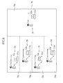
- an endoscope examination room 70 is separated into plural examination rooms 70a-70e by partitions or the like.
- electronic endoscope apparatuses 2a-2e are disposed in the examination rooms 70a-70e.
- the electronic endoscope apparatuses 2a-2e are respectively constituted of electronic endoscopes 10a-10e and processors 11a-11e.
- the channels one-four of the second frequency band are currently used by the electronic endoscope apparatuses 2a-2d.
- the electronic endoscope 10e is wirelessly connected to the processor 11e to perform the endoscopic diagnosis.
- suffixes a-e corresponding to the electronic endoscope apparatus 2a-2e are added to the numerals of parts in the electronic endoscope apparatuses 2a-2e.
- the channel allocation request signal Sa is transmitted from the first channel detection circuit 43e in the electronic endoscope 10e to the second channel detection circuit 63e in the processor 11e.
- the first channel detection circuit 43e When the first channel detection circuit 43e receives the channel number notification signal Sc from the second channel detection circuit 63e, the first channel detection circuit 43e transmits the notified available channel number (in this case, the channel five in the second frequency band) to the CPU 30e and the transmission frequency band switching circuit 42e.
- the notified available channel number in this case, the channel five in the second frequency band
- the transmission frequency band switching circuit 42e is not actuated, and the initially set second frequency band transmission circuit 41e is used.
- the endoscopic diagnosis is started by using the notified available channel, that is, in this case, the channel five in the second frequency band.
- the channels one-five are allocated to the second frequency band, it is possible to use five electronic endoscopes 10a-10e at the same time within the second frequency band.
- the channel five in the second frequency band is used by the fifth electronic endoscope 10e, and the four other channels in the second frequency band are already used by the electronic endoscopes 10a-10d, there is no available channel left in the second frequency band.
- the first channel detection circuit 43f receives the channel number notification signal Sc (in this case, one of the channels one-five in the first frequency band, for instance, the channel one) from the second channel detection circuit 63f and transmits the notified channel number to the CPU 30f and the transmission frequency band switching circuit 42f.
- the transmission frequency band switching circuit 42f switches from the second frequency band transmission circuit 41f to the first frequency band transmission circuit 40f.
- the notified available channel that is, the channel one in the first frequency band is used to start the endoscopic diagnosis.
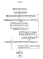
- the second channel detection circuit 63e receives the channel-in-use notification signals Sb transmitted at the constant intervals from the first channel detection circuits 43a-43d in the electronic endoscopes 10a-10d (see Fig. 6) .
- the channel-in-use notification signals Sb notify that the channels one-four in the second frequency band are used.
- the second channel detection circuit 63e upon receiving the channel allocation request signal Sa transmitted from the first channel detection circuit 43e of the electronic endoscope 10e, the second channel detection circuit 63e checks the available channel in the second frequency band based on the channel usage condition notified by the channel-in-use notification signals Sb, and detects that the channel five is available.
- the second channel detection circuit 63e transmits the channel number notification signal Sc (in this case, a signal notifying the channel five in the second frequency band is available) to the first channel detection circuit 43e according to the detection result.
- the reception frequency band switching circuit 62 is not actuated.
- the processor 11e uses the notified available channel, that is, the channel five in the second frequency band reception circuit 61e to receive the radio wave 12e from the electronic endoscope 10e.
- the second channel detection circuit 63f checks the available channel in the first frequency band, and detects that the channels one-five are available.
- the second channel detection circuit 63f transmits the channel number notification signal Sc (in this case, a signal notifying that one of the channels one-five in the first frequency band, for instance, the channel one is available) to the first channel detection circuit 43f according to the above detection results.
- the reception frequency band switching circuit 62f switches from the second frequency band reception circuit 61f to the first frequency band reception circuit 60f, and the processor 11f receives the radio wave 12f from the electronic endoscope 10f using the detected available channel, that is, the channel one in the first frequency band.
- the electronic endoscope 10k When ten sets of electronic endoscopes 2a-2j, that is, ten electronic endoscopes 10a-10j and ten processors 11a-11j are provided and currently used for the endoscopic diagnoses, there is no available channel in either of the first and the second frequency bands.
- the electronic endoscope 10k In order to use eleventh electronic endoscope 10k, the electronic endoscope 10k remains in a standby state until the examination using one of the electronic endoscopes 10a-10j, for instance, the electronic endoscope 10a is completed and the power of the electronic endoscope 10a is turned off to vacate one channel and the channel number notification signal Sc is received from the second channel detection section 63a.
- the second channel detection circuit 63a is not able to receive the channel allocation request signal Sa from the first channel detection circuit 43k while the electronic endoscope 10a is used. When the power of the electronic endoscope 10a is turned off, the second channel detection circuit 63a returns to the state for receiving the channel allocation request signal Sa. Upon receiving the channel allocation request signal Sa from the first channel detection circuit 43k, the second channel detection circuit 63a detects that the channel which had been used by the electronic endoscope 10a is now available according to the usage condition notified by the channel-in-use notification signals Sb. Thereby, the second channel detection circuit 63a transmits the available channel number to the first channel detection circuit 43k.
- the electronic endoscope 10 and the processor 11 of the electronic endoscope apparatus 2 transmit and receive signals via the radio waves 12 within predetermined frequency bands to which plural channels are respectively allocated.
- the electronic endoscope 10 has the transmission frequency band switching circuit 42 which switches between the first and second frequency bands, and the first channel detection circuit 43 for detecting the available channel.
- the processor 11 has the reception frequency band switching circuit 62 which switches between the first and second frequency bands, and the second channel detection circuit 63 for detecting the available channel.
- the transmission and reception frequency band switching circuits 42, 62 automatically switch the transmission and reception frequency bands according to detection results of the first and second channel detection circuits 43, 63. Accordingly, the radio interference between the electronic endoscope apparatuses is securely prevented. Further, since it is no longer necessary to manually set the channels and the frequency bands, the operability of the electronic endoscope apparatus is improved.
- the electronic endoscope 2 for medical uses is described as an example.
- the present invention is not limited to the above, and is also applicable to industrial uses.
Landscapes
- Health & Medical Sciences (AREA)
- Life Sciences & Earth Sciences (AREA)
- Engineering & Computer Science (AREA)
- Surgery (AREA)
- Pathology (AREA)
- Animal Behavior & Ethology (AREA)
- Veterinary Medicine (AREA)
- Biophysics (AREA)
- Public Health (AREA)
- General Health & Medical Sciences (AREA)
- Physics & Mathematics (AREA)
- Molecular Biology (AREA)
- Medical Informatics (AREA)
- Biomedical Technology (AREA)
- Heart & Thoracic Surgery (AREA)
- Radiology & Medical Imaging (AREA)
- Optics & Photonics (AREA)
- Nuclear Medicine, Radiotherapy & Molecular Imaging (AREA)
- Computer Networks & Wireless Communication (AREA)
- Multimedia (AREA)
- Signal Processing (AREA)
- Endoscopes (AREA)
- Closed-Circuit Television Systems (AREA)
Applications Claiming Priority (1)
| Application Number | Priority Date | Filing Date | Title |
|---|---|---|---|
| JP2005090685A JP2006271432A (ja) | 2005-03-28 | 2005-03-28 | 電子内視鏡装置 |
Publications (3)
| Publication Number | Publication Date |
|---|---|
| EP1707106A2 true EP1707106A2 (de) | 2006-10-04 |
| EP1707106A3 EP1707106A3 (de) | 2008-04-02 |
| EP1707106B1 EP1707106B1 (de) | 2011-07-20 |
Family
ID=36616798
Family Applications (1)
| Application Number | Title | Priority Date | Filing Date |
|---|---|---|---|
| EP06006426A Expired - Fee Related EP1707106B1 (de) | 2005-03-28 | 2006-03-28 | Elektronisches Endoskop |
Country Status (3)
| Country | Link |
|---|---|
| US (1) | US20060217591A1 (de) |
| EP (1) | EP1707106B1 (de) |
| JP (1) | JP2006271432A (de) |
Cited By (2)
| Publication number | Priority date | Publication date | Assignee | Title |
|---|---|---|---|---|
| CN102740759A (zh) * | 2009-06-10 | 2012-10-17 | 奥林巴斯株式会社 | 无线内窥镜装置、其接收装置以及接收方法 |
| EP2478823A4 (de) * | 2009-10-23 | 2012-10-24 | Olympus Corp | Tragbares drahtloses endgerät, drahtloses endgerät, drahtloses kommunikationssystem und drahtloses kommunikationsverfahren |
Families Citing this family (8)
| Publication number | Priority date | Publication date | Assignee | Title |
|---|---|---|---|---|
| JP4781764B2 (ja) * | 2005-09-29 | 2011-09-28 | 富士フイルム株式会社 | 電子内視鏡システム |
| JP5226354B2 (ja) | 2008-03-27 | 2013-07-03 | オリンパス株式会社 | 無線撮像システム及び撮像装置 |
| JP5155037B2 (ja) * | 2008-06-30 | 2013-02-27 | オリンパス株式会社 | 受像機及び画像送信機からなる無線通信システム及び、その無線通信方法 |
| EP2359598A1 (de) * | 2008-11-21 | 2011-08-24 | Stryker Corporation | Drahtloses operationsraum-kommunikationssystem mit videoausgabeeinrichtung und videoanzeige |
| US20110218400A1 (en) * | 2010-03-05 | 2011-09-08 | Tyco Healthcare Group Lp | Surgical instrument with integrated wireless camera |
| JP5945384B2 (ja) * | 2010-08-04 | 2016-07-05 | オリンパス株式会社 | 無線画像通信システム、受信機、送信機、およびプログラム |
| EP2648603B1 (de) | 2010-12-08 | 2020-02-05 | The Board of Regents of the University of Nebraska | Tragbares laparoskopsystem |
| JP6395445B2 (ja) * | 2014-05-28 | 2018-09-26 | オリンパス株式会社 | 内視鏡、受信装置、無線内視鏡システム、画像受信装置の作動方法、およびプログラム |
Family Cites Families (19)
| Publication number | Priority date | Publication date | Assignee | Title |
|---|---|---|---|---|
| JPS5594235A (en) * | 1979-01-11 | 1980-07-17 | Olympus Optical Co | Endoscope photographing device |
| JPS6048011A (ja) * | 1983-08-27 | 1985-03-15 | Olympus Optical Co Ltd | 内視鏡装置 |
| JPS62128225A (ja) * | 1985-11-29 | 1987-06-10 | Iwatsu Electric Co Ltd | 無線ペ−ジング通信方式 |
| JPH05110522A (ja) * | 1991-06-13 | 1993-04-30 | Fujitsu Ltd | 空きチヤネル検出方式 |
| JPH05191313A (ja) * | 1992-01-16 | 1993-07-30 | Aruinko Kk | 無線通信機 |
| CA2118273C (en) * | 1993-11-23 | 2000-04-25 | Pi-Hui Chao | Method and apparatus for dynamic channel allocation for wireless communication |
| JPH0998470A (ja) * | 1995-09-29 | 1997-04-08 | Tateyama Kagaku Kogyo Kk | 無線通信装置 |
| US6496490B1 (en) * | 1998-07-09 | 2002-12-17 | Lucent Technologies Inc. | Method for dynamically allocating carriers in a wireless packet network, with reuse of carriers |
| JP3583660B2 (ja) * | 1999-08-05 | 2004-11-04 | オリンパス株式会社 | 内視鏡装置 |
| JP2001353124A (ja) * | 2000-04-10 | 2001-12-25 | Olympus Optical Co Ltd | 内視鏡装置 |
| US20030093503A1 (en) * | 2001-09-05 | 2003-05-15 | Olympus Optical Co., Ltd. | System for controling medical instruments |
| JP3621688B2 (ja) * | 2002-04-01 | 2005-02-16 | 富士通株式会社 | 移動通信端末および通話チャネル制御方法 |
| JP2004267461A (ja) * | 2003-03-07 | 2004-09-30 | Olympus Corp | 内視鏡手術システム |
| CA2523290A1 (en) * | 2003-04-25 | 2004-11-11 | Olympus Corporation | Wireless in-vivo information acquiring system and external device |
| EP1625671B1 (de) * | 2003-05-09 | 2014-05-07 | Philips Intellectual Property & Standards GmbH | Verfahren zum aufbauen einer drahtlosen kommunikationsverbindung |
| JP3891436B2 (ja) * | 2003-07-08 | 2007-03-14 | 株式会社エヌ・ティ・ティ・ドコモ | 通信制御装置 |
| JP2004113805A (ja) * | 2003-10-07 | 2004-04-15 | Olympus Corp | 手術システムの制御方法 |
| US7297105B2 (en) * | 2004-02-10 | 2007-11-20 | Mackin Robert A | Endotracheal camera |
| US20070162089A1 (en) * | 2006-01-09 | 2007-07-12 | Transoma Medical, Inc. | Cross-band communications in an implantable device |
-
2005
- 2005-03-28 JP JP2005090685A patent/JP2006271432A/ja not_active Abandoned
-
2006
- 2006-03-27 US US11/388,997 patent/US20060217591A1/en not_active Abandoned
- 2006-03-28 EP EP06006426A patent/EP1707106B1/de not_active Expired - Fee Related
Non-Patent Citations (1)
| Title |
|---|
| None |
Cited By (5)
| Publication number | Priority date | Publication date | Assignee | Title |
|---|---|---|---|---|
| CN102740759A (zh) * | 2009-06-10 | 2012-10-17 | 奥林巴斯株式会社 | 无线内窥镜装置、其接收装置以及接收方法 |
| EP2441380A4 (de) * | 2009-06-10 | 2013-01-02 | Olympus Corp | Drahtlose endoskopvorrichtung, empfangsgerät dafür und empfangsverfahren |
| CN102740759B (zh) * | 2009-06-10 | 2016-03-16 | 奥林巴斯株式会社 | 无线内窥镜装置、其接收装置以及接收方法 |
| EP2478823A4 (de) * | 2009-10-23 | 2012-10-24 | Olympus Corp | Tragbares drahtloses endgerät, drahtloses endgerät, drahtloses kommunikationssystem und drahtloses kommunikationsverfahren |
| US9002285B2 (en) | 2009-10-23 | 2015-04-07 | Olympus Corporation | Portable wireless terminal, wireless terminal, wireless communication system, and wireless communication method |
Also Published As
| Publication number | Publication date |
|---|---|
| EP1707106B1 (de) | 2011-07-20 |
| JP2006271432A (ja) | 2006-10-12 |
| EP1707106A3 (de) | 2008-04-02 |
| US20060217591A1 (en) | 2006-09-28 |
Similar Documents
| Publication | Publication Date | Title |
|---|---|---|
| US10973390B2 (en) | Wireless endoscope and wireless endoscope system | |
| JP4530931B2 (ja) | 撮像表示システムおよび被検体内留置システム | |
| US8764634B2 (en) | Imaging apparatus | |
| KR100741217B1 (ko) | 무선형 피검체 내 정보 취득 시스템 및 피검체 외부 장치 | |
| JP5259174B2 (ja) | 送受信システム | |
| JP2006271697A (ja) | 電子内視鏡 | |
| EP1707106B1 (de) | Elektronisches Endoskop | |
| JP2009189663A (ja) | 内視鏡装置 | |
| EP2042077B1 (de) | Elektronisches Endoskop und endoskopisches System | |
| EP1929933A2 (de) | Endoskopisches Diagnosesystem | |
| US7999845B2 (en) | Electronic endoscope system | |
| WO2007034891A1 (ja) | 受信装置 | |
| JP3583660B2 (ja) | 内視鏡装置 | |
| US7758496B2 (en) | Diagnostic system using endoscope | |
| JP3762612B2 (ja) | 医療システム及び内視鏡装置 | |
| JP4303053B2 (ja) | カプセル内視鏡誘導システム | |
| US8294751B2 (en) | Electronic endoscope system | |
| JP4472049B2 (ja) | 電子内視鏡装置 | |
| JP2008073376A (ja) | カプセル型内視鏡システム | |
| JP2007061296A (ja) | 電子内視鏡用受信モジュール及び画像処理装置 | |
| JP4542398B2 (ja) | 受信装置 | |
| JP4887063B2 (ja) | 電子内視鏡 | |
| JP2010131125A (ja) | 医療用プローブ付き電子内視鏡 | |
| KR20180078503A (ko) | 마그네틱 센서를 이용한 캡슐 내시경 장치의 동작 방법 및 상기 방법을 사용하는 캡슐 내시경 장치, 및 캡슐 내시경 시스템 |
Legal Events
| Date | Code | Title | Description |
|---|---|---|---|
| PUAI | Public reference made under article 153(3) epc to a published international application that has entered the european phase |
Free format text: ORIGINAL CODE: 0009012 |
|
| AK | Designated contracting states |
Kind code of ref document: A2 Designated state(s): AT BE BG CH CY CZ DE DK EE ES FI FR GB GR HU IE IS IT LI LT LU LV MC NL PL PT RO SE SI SK TR |
|
| AX | Request for extension of the european patent |
Extension state: AL BA HR MK YU |
|
| PUAL | Search report despatched |
Free format text: ORIGINAL CODE: 0009013 |
|
| AK | Designated contracting states |
Kind code of ref document: A3 Designated state(s): AT BE BG CH CY CZ DE DK EE ES FI FR GB GR HU IE IS IT LI LT LU LV MC NL PL PT RO SE SI SK TR |
|
| AX | Request for extension of the european patent |
Extension state: AL BA HR MK YU |
|
| 17P | Request for examination filed |
Effective date: 20081001 |
|
| AKX | Designation fees paid |
Designated state(s): DE FR GB |
|
| 17Q | First examination report despatched |
Effective date: 20100609 |
|
| GRAP | Despatch of communication of intention to grant a patent |
Free format text: ORIGINAL CODE: EPIDOSNIGR1 |
|
| GRAS | Grant fee paid |
Free format text: ORIGINAL CODE: EPIDOSNIGR3 |
|
| GRAA | (expected) grant |
Free format text: ORIGINAL CODE: 0009210 |
|
| RIN1 | Information on inventor provided before grant (corrected) |
Inventor name: ABE, KAZUNORI |
|
| AK | Designated contracting states |
Kind code of ref document: B1 Designated state(s): DE FR GB |
|
| REG | Reference to a national code |
Ref country code: GB Ref legal event code: FG4D |
|
| REG | Reference to a national code |
Ref country code: DE Ref legal event code: R096 Ref document number: 602006023125 Country of ref document: DE Effective date: 20110915 |
|
| PLBE | No opposition filed within time limit |
Free format text: ORIGINAL CODE: 0009261 |
|
| STAA | Information on the status of an ep patent application or granted ep patent |
Free format text: STATUS: NO OPPOSITION FILED WITHIN TIME LIMIT |
|
| 26N | No opposition filed |
Effective date: 20120423 |
|
| REG | Reference to a national code |
Ref country code: DE Ref legal event code: R097 Ref document number: 602006023125 Country of ref document: DE Effective date: 20120423 |
|
| REG | Reference to a national code |
Ref country code: FR Ref legal event code: PLFP Year of fee payment: 10 |
|
| PGFP | Annual fee paid to national office [announced via postgrant information from national office to epo] |
Ref country code: DE Payment date: 20150324 Year of fee payment: 10 |
|
| PGFP | Annual fee paid to national office [announced via postgrant information from national office to epo] |
Ref country code: FR Payment date: 20150309 Year of fee payment: 10 Ref country code: GB Payment date: 20150325 Year of fee payment: 10 |
|
| REG | Reference to a national code |
Ref country code: DE Ref legal event code: R119 Ref document number: 602006023125 Country of ref document: DE |
|
| GBPC | Gb: european patent ceased through non-payment of renewal fee |
Effective date: 20160328 |
|
| REG | Reference to a national code |
Ref country code: FR Ref legal event code: ST Effective date: 20161130 |
|
| PG25 | Lapsed in a contracting state [announced via postgrant information from national office to epo] |
Ref country code: DE Free format text: LAPSE BECAUSE OF NON-PAYMENT OF DUE FEES Effective date: 20161001 Ref country code: FR Free format text: LAPSE BECAUSE OF NON-PAYMENT OF DUE FEES Effective date: 20160331 Ref country code: GB Free format text: LAPSE BECAUSE OF NON-PAYMENT OF DUE FEES Effective date: 20160328 |