EP1707525B1 - Kabelaufwickelvorrichtung für elektrische Haushaltsgeräte - Google Patents
Kabelaufwickelvorrichtung für elektrische Haushaltsgeräte Download PDFInfo
- Publication number
- EP1707525B1 EP1707525B1 EP06356017A EP06356017A EP1707525B1 EP 1707525 B1 EP1707525 B1 EP 1707525B1 EP 06356017 A EP06356017 A EP 06356017A EP 06356017 A EP06356017 A EP 06356017A EP 1707525 B1 EP1707525 B1 EP 1707525B1
- Authority
- EP
- European Patent Office
- Prior art keywords
- cord
- reel
- stage
- drum
- compensation chamber
- Prior art date
- Legal status (The legal status is an assumption and is not a legal conclusion. Google has not performed a legal analysis and makes no representation as to the accuracy of the status listed.)
- Expired - Lifetime
Links
Images



Classifications
-
- B—PERFORMING OPERATIONS; TRANSPORTING
- B65—CONVEYING; PACKING; STORING; HANDLING THIN OR FILAMENTARY MATERIAL
- B65H—HANDLING THIN OR FILAMENTARY MATERIAL, e.g. SHEETS, WEBS, CABLES
- B65H75/00—Storing webs, tapes, or filamentary material, e.g. on reels
- B65H75/02—Cores, formers, supports, or holders for coiled, wound, or folded material, e.g. reels, spindles, bobbins, cop tubes, cans, mandrels or chucks
- B65H75/34—Cores, formers, supports, or holders for coiled, wound, or folded material, e.g. reels, spindles, bobbins, cop tubes, cans, mandrels or chucks specially adapted or mounted for storing and repeatedly paying-out and re-storing lengths of material provided for particular purposes, e.g. anchored hoses, power cables
- B65H75/38—Cores, formers, supports, or holders for coiled, wound, or folded material, e.g. reels, spindles, bobbins, cop tubes, cans, mandrels or chucks specially adapted or mounted for storing and repeatedly paying-out and re-storing lengths of material provided for particular purposes, e.g. anchored hoses, power cables involving the use of a core or former internal to, and supporting, a stored package of material
- B65H75/44—Constructional details
- B65H75/4418—Arrangements for stopping winding or unwinding; Arrangements for releasing the stop means
- B65H75/4428—Arrangements for stopping winding or unwinding; Arrangements for releasing the stop means acting on the reel or on a reel blocking mechanism
- B65H75/4431—Manual stop or release button
-
- B—PERFORMING OPERATIONS; TRANSPORTING
- B65—CONVEYING; PACKING; STORING; HANDLING THIN OR FILAMENTARY MATERIAL
- B65H—HANDLING THIN OR FILAMENTARY MATERIAL, e.g. SHEETS, WEBS, CABLES
- B65H75/00—Storing webs, tapes, or filamentary material, e.g. on reels
- B65H75/02—Cores, formers, supports, or holders for coiled, wound, or folded material, e.g. reels, spindles, bobbins, cop tubes, cans, mandrels or chucks
- B65H75/34—Cores, formers, supports, or holders for coiled, wound, or folded material, e.g. reels, spindles, bobbins, cop tubes, cans, mandrels or chucks specially adapted or mounted for storing and repeatedly paying-out and re-storing lengths of material provided for particular purposes, e.g. anchored hoses, power cables
- B65H75/38—Cores, formers, supports, or holders for coiled, wound, or folded material, e.g. reels, spindles, bobbins, cop tubes, cans, mandrels or chucks specially adapted or mounted for storing and repeatedly paying-out and re-storing lengths of material provided for particular purposes, e.g. anchored hoses, power cables involving the use of a core or former internal to, and supporting, a stored package of material
- B65H75/44—Constructional details
- B65H75/4449—Arrangements or adaptations to avoid movable contacts or rotary couplings, e.g. by the use of an expansion chamber for a lenght of the cord or hose
-
- B—PERFORMING OPERATIONS; TRANSPORTING
- B65—CONVEYING; PACKING; STORING; HANDLING THIN OR FILAMENTARY MATERIAL
- B65H—HANDLING THIN OR FILAMENTARY MATERIAL, e.g. SHEETS, WEBS, CABLES
- B65H75/00—Storing webs, tapes, or filamentary material, e.g. on reels
- B65H75/02—Cores, formers, supports, or holders for coiled, wound, or folded material, e.g. reels, spindles, bobbins, cop tubes, cans, mandrels or chucks
- B65H75/34—Cores, formers, supports, or holders for coiled, wound, or folded material, e.g. reels, spindles, bobbins, cop tubes, cans, mandrels or chucks specially adapted or mounted for storing and repeatedly paying-out and re-storing lengths of material provided for particular purposes, e.g. anchored hoses, power cables
- B65H75/38—Cores, formers, supports, or holders for coiled, wound, or folded material, e.g. reels, spindles, bobbins, cop tubes, cans, mandrels or chucks specially adapted or mounted for storing and repeatedly paying-out and re-storing lengths of material provided for particular purposes, e.g. anchored hoses, power cables involving the use of a core or former internal to, and supporting, a stored package of material
- B65H75/44—Constructional details
- B65H75/48—Automatic re-storing devices
- B65H75/486—Arrangements or adaptations of the spring motor
Definitions
- the present invention relates to a cord retractor device for a household appliance, and more particularly relates to a cord retractor device adapted to store a cord enclosing a conduit for the transport of a fluid, such as a cord brought with steam, and / or a power supply cable.
- the automatic cord rewinders comprise a rotating drum on which the cord is wound and a rotating connector at the fixed end of the cord so that the cord is not twisted by the different drum turns.
- the rotating connectors have the disadvantage of being relatively complex, especially when the cord contains a conduit for the transport of a fluid, which poses problems of cost and reliability.
- Such a winding device however has the disadvantage of having a large axial size.
- such a retractor in order to function, must have a length of the cord in the compensation chamber close to that of the cord that can actually be extracted from the retractor. It follows a relatively high cost for a cord length that is hidden and is not available to the user.
- an object of the present invention is to overcome these disadvantages by providing a cord winder device comprising a compensation chamber, wherein only a reduced length of spiral cord remains trapped in the compensation chamber.
- the object of the present invention is also to provide a retractor device having a reduced axial size to facilitate its integration into the base of the device.
- the subject of the invention is a cord retractor device for a household appliance comprising a rotary drum comprising a winding surface on which can wind a first cord portion corresponding to the cord length that can be extracted from the device. winder, the end of the first bead portion engaging through an orifice within a compensation chamber radially disposed within the winding surface and wherein the first bead portion is extended by a second cord portion extending in the form of a spiral, the cord winding in the same direction on the drum and in the compensation chamber, the cord being locally fixed on the drum near the orifice and having an end coming out of the compensation chamber for its connection to a fixed element of the apparatus, characterized in that the compensation chamber comprises at least one oins a first stage extending axially over substantially the entire width of the winding surface and a second stage axially offset from the first stage and in that the device comprises a return module, ensuring the automatic return of the drum in the direction of the winding of the first cord portion, disposed in a housing
- Such a characteristic makes it possible to obtain a winding device without a rotating connection, operating with a length of cord in the compensation chamber that is clearly smaller than the length of cord that can be extracted from the winding device. Such a feature also reduces the axial size of the winder device.
- the second stage is defined radially by a wall carried by a hood and the return module is disposed in a housing of said hood on the edge of the second floor.
- the return module comprises a pinion which meshes with a toothed wheel integral with rotation of the drum.
- the return module contains spring means and comprises a ratchet system which prevents the rotation of the return module in the direction of the winding of the cord on the drum, the ratchet system being disengageable by means of a button.
- the stages have a common wall comprising a central opening for the passage from one stage to another, the central opening being carried by a free piece rotating on the common wall.
- the length of the second bead portion is equitably distributed between the different stages.
- the first and second cord portions contain a steam duct and a power supply cable.
- the retractor device is intended to equip a steam iron with separate steam generator.
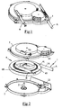
- the figure 1 represents a cord winder device intended to equip a steam generating apparatus, such as a separate steam generator iron, such a device for storing a cord 1 having a first end A intended to be connected to a iron or steam brush and a second end B to be fixedly connected to the base of the steam generator.
- the cord 1 advantageously contains a steam duct for transferring the steam from the base to the iron and a power supply cable used for example to electrically power the soleplate of the iron.
- the cord winding device comprises a lower cover 2 and an upper cover 3, assembled one on the other, which contain a drum 4 rotatably mounted about an axis 21 carried by the lower cover 2.
- the drum 4 comprises an upper disc 41, shown alone on the figure 3b , having a lower surface comprising a set of projecting walls defining a substantially cylindrical winding surface 42 against which is advantageously snapped a lower disk 43, the latter being represented only on the figures 3a and 10 to clarify more.
- the upper disc 41 comprises a central piece 44, having a circular contour, which is mounted free to rotate relative to the body of the upper disc 41.
- This central piece 44 has a tubular portion 44A which engages on the axis 21 of the hood lower 3 and comprises an opening 44B lined with a spiral guide wall.
- the winding surface 42 receives a first bead portion 1A corresponding to the length of cord that can be pulled out of the winder device, this first bead portion 1A being wound up several turns around said winding surface 42, as well as the can be seen on the figure 4 and 5 .
- the length of this first cord portion 1A is advantageously of the order of 140 cm so as to provide sufficient freedom of movement to the user when using the accessory connected to the end A cord.
- the winding surface 42 comprises an opening 42A through which the cord 1 passes, the end of the first cord portion 1A being fixed to the drum by a flange 7A and being connected, by means of from a connector 5, to a second cord portion 1 B which winds in a spiral inside a compensation chamber 6 delimited radially by the walls of the winding surface 42.
- This compensation chamber 6 comprises a first stage 61, delimited laterally by the upper disks 41 and lower 43 of the drum 4, in which the second cord portion 1B spirally winds from the connector 5, which is fixed on the drum 4 near the winding surface 42, to the center of the drum 4 where the second bead portion 1B fits into the opening 44B of the central piece 44 to emerge on the other side of the upper disk 41.
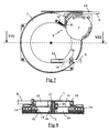
- the cord 1 opens into a second stage 62 of the compensation chamber 6 delimited radially by a substantially cylindrical wall 31, visible on the figures 4 and 8 carried by the upper cover 3 and whose diameter substantially corresponds to the inside diameter of the winding surface 42.
- the cord 1 spirally winds in this second stage 62 starting from the central piece 44 to the periphery of the compensation chamber 6, the cord 1 passing through a lateral opening 31A of the substantially cylindrical wall 31 to exit through a slot 3A facing provided on the upper cover 3, the cord 1 being immobilized by a flange 7B on the upper cover upstream of the end B.
- the second cord portion 1B is thus held fixedly to the drum 4 at the connector 5 and is immobilized at the exit of the winder device, the length of the second cord portion 1B being adapted so that the spirals in the two stages 61, 62 of the compensation chamber 6 are loose when the first cord portion 1A is wound on the winding surface 42 as is shown in FIGS. Figures 5 and 6 .
- the total length of the second bead portion 1B contained in the compensation chamber 6 is of the order of 70 cm, this length being equitably distributed between the first and second stages 61, 62.
- the upper face of the upper disk 41 comprises a toothed wheel 45 which cooperates with the teeth of a pinion 81 carried by a return module 8, the radius of the pinion 81 being advantageously less than the radius of the toothed wheel 45, for example equal at half of the latter, so that the rotation of the drum 4 is accompanied by a greater number of revolutions of the return module 8.
- the return module 8 is disposed in a housing of the upper cover 3 provided for this purpose at the periphery of the drum 4 and has a cylindrical body which is rotatably mounted about an axis 22 carried by the lower cover 2.
- the module recall 8 contains spring means, not shown in the figures, which are bandaged when the cord 1 is unwound from the drum 4.
- the spring means may be constituted by a spiral spring whose one end is integral with the rotation axis 22 and the other end is secured to the body of the return module 8.
- the return module 8 also comprises a ratchet system 9 which prevents the rotation of the module 8 in the rewinding direction of the drum 4.
- This ratchet system conventionally comprises a pivoting cleat 91 applied by means of a spring 92 against a track toothed 82 formed on the periphery of the body of the return module 8, the cleat 91 can be removed from the toothed track by pressing a push button 93.
- the Figures 5 and 6 illustrate the positioning of the cord 1 when the latter is stored in the winding device. According to these figures, in this position, the first cord portion 1A, which corresponds to the length of cord that can be extracted from the winder device by the user, is wound around the winding surface 42 of the drum and the spiral formed by the second cord portion 1B contained in the two stages 61, 62, is loose.
- the user When the user wishes to extract the cord 1 of the retractor, he pulls on the end A of the cord which causes the rotation of the drum 4 in the direction of the arrow illustrated on the Figures 9 and 10 so that the first cord portion 1A wound on the winding surface 42 exits the winder device.
- the first cord portion 1A can thus be extracted from the winding device over substantially its entire length, the flange 7A disposed at the end of the first cord portion 1A preventing the connector 5 from being forced to tear when the The user draws on the cord 1.
- the extraction of the first cord portion 1A along its entire length causes the drum 4 to rotate about three turns, this rotation of the drum 4 being accompanied by a rotation of the return module 8 over nearly six revolutions, which causes the spring means that it contains to be energized, the rotation in the opposite direction of the return module 8 being prevented by the presence of the cleat 91 on the toothed track 82.
- the rotation of the drum 4 over nearly three turns causes the tightening of the second part of cord 1 B spiral on less than one and a half turns for each of the stages 61, 62 of the compensation chamber 6, the winding being equitably distributed on each of the stages thanks to the free rotation of the central piece 44.
- Such a device comprising a compensation chamber arranged radially inside the winding drum has the advantage of only requiring a reduced length of cord in the compensation chamber, which significantly reduces the cost of this length. cord that is not extractable from the reel and is therefore not recoverable from the user.
- the winding device thus produced also has the advantage of having a reduced axial size, that is to say a small thickness, especially up to the winding diameter of the drum.
- the use of a multi-stage compensation chamber makes it possible to reduce the radial space required for the spiral winding of the second bead portion and thus to reduce the radial size of the compensation chamber.
- the retractor device may comprise more than two stages so as to further reduce clutter. radial of the compensation chamber.
Landscapes
- Storing, Repeated Paying-Out, And Re-Storing Of Elongated Articles (AREA)
- Yarns And Mechanical Finishing Of Yarns Or Ropes (AREA)
- Ropes Or Cables (AREA)
- Massaging Devices (AREA)
- Communication Cables (AREA)
- Insulated Conductors (AREA)
- Storage Of Web-Like Or Filamentary Materials (AREA)
Claims (8)
- Kabelaufwicklungsvorrichtung für ein Elektrohaushaltsgerät, mit einer drehenden Trommel (4), die eine Aufwickelfläche (42) aufweist, auf welcher sich ein erster Kabelteil (1A) aufwickeln kann, der der Kabellänge entspricht, die aus der Aufwicklungsvorrichtung entnommen werden kann, wobei das Ende des ersten Kabelteils (1A) durch eine Öffnung (42A) ins Innere einer Ausgleichskammer (6) eingreifen kann, die radial innerhalb der Aufwickelfläche (42) angeordnet ist und in welcher der erste Kabelteil (1A) durch einen zweiten Kabelteil (1 B) verlängert wird, der sich spiralförmig erstreckt, wobei sich das Kabel (1) in die gleiche Richtung auf der Trommel (4) und in der Ausgleichskammer (6) aufwickelt, wobei das Kabel (1) auf der Trommel (4) in der Nähe der Öffnung (42A) örtlich befestigt ist und ein Ende (B) aufweist, das aus der Ausgleichskammer (6) heraustritt, um an einen feststehenden Element des Geräts angeschlossen zu werden, dadurch gekennzeichnet, dass die Ausgleichskammer (6) mindestens eine erste Stufe (61), die sich auf im Wesentlichen der ganzen Breite der Aufwickelfläche (42) axial erstreckt, und eine zweite Stufe (62) aufweist, die zur ersten Stufe (61) axial verschoben ist, und dass die Vorrichtung ein Rückstellmodul (8) aufweist, das das automatische Rückstellen der Trommel (4) in der Aufwickelrichtung des ersten Kabelteils (1 A) gewährleistet, das in einer Aufnahme am Umfang der Trommel (4) angeordnet ist.
- Kabelaufwicklungsvorrichtung nach Anspruch 1, dadurch gekennzeichnet, dass die zweite Stufe (62) radial durch eine Wand (31) begrenzt ist, die von einer Haube (3) getragen ist, und dass das Rückstellmodul (8) in der Aufnahme der Haube (3) am Rand der zweiten Stufe (62) angeordnet ist.
- Kabelaufwicklungsvorrichtung nach einem der Ansprüche 1 bis 2, dadurch gekennzeichnet, dass das Rückstellmodul (8) ein Ritzel (81) aufweist, das in ein Zahnrad (45) eingreift, das mit der Trommel (4) drehverbunden ist.
- Kabelaufwicklungsvorrichtung nach einem der Ansprüche 1 bis 3, dadurch gekennzeichnet, dass das Rückstellmodul (8) Federmittel einschließt und ein System mit Klinke (9) aufweist, das die Drehung des Rückstellmoduls (8) in Aufwickelrichtung des Kabels (1) auf der Trommel (4) verhindert. wobei das System mit Klinke (9) mittels eines Knopfs (93) ausrückbar ist.
- Kabelaufwicklungsvorrichtung nach einem der Ansprüche 1 bis 4, dadurch gekennzeichnet, dass die Stufen (61, 62) eine gemeinsame Wand (41) aufweisen, die eine zentrale Öffnung (44B) für den Übergang von einer Stufe zur anderen umfasst, wobei die zentrale Öffnung (44B) von einem frei drehbaren Teil (44) an der gemeinsamen Wand (41) getragen ist.
- Kabelaufwicklungsvorrichtung nach einem der Ansprüche 1 bis 5, dadurch gekennzeichnet, dass die Länge des zweiten Kabelteils (1 B) zwischen den verschiedenen Stufen (61, 62) gleichmäßig verteilt ist.
- Kabelaufwicklungsvorrichtung nach einem der Ansprüche 1 bis 6, dadurch gekennzeichnet, dass der erste und der zweite Teil des Kabels (1A, 1 B) eine Dampfleitung und ein elektrisches Netzkabel einschließen.
- Kabelaufwicklungsvorrichtung nach Anspruch 7, dadurch gekennzeichnet, dass es dazu dient, ein Bügeleisen mit getrenntem Dampfgenerator auszustatten.
Priority Applications (1)
| Application Number | Priority Date | Filing Date | Title |
|---|---|---|---|
| PL06356017T PL1707525T3 (pl) | 2005-03-31 | 2006-02-16 | Urządzenie zwijające sznur dla urządzenia elektrycznego gospodarstwa domowego |
Applications Claiming Priority (1)
| Application Number | Priority Date | Filing Date | Title |
|---|---|---|---|
| FR0503125A FR2883854B1 (fr) | 2005-03-31 | 2005-03-31 | Dispositif enrouleur de cordon pour appareil electromenager |
Publications (2)
| Publication Number | Publication Date |
|---|---|
| EP1707525A1 EP1707525A1 (de) | 2006-10-04 |
| EP1707525B1 true EP1707525B1 (de) | 2008-12-17 |
Family
ID=35285262
Family Applications (1)
| Application Number | Title | Priority Date | Filing Date |
|---|---|---|---|
| EP06356017A Expired - Lifetime EP1707525B1 (de) | 2005-03-31 | 2006-02-16 | Kabelaufwickelvorrichtung für elektrische Haushaltsgeräte |
Country Status (8)
| Country | Link |
|---|---|
| EP (1) | EP1707525B1 (de) |
| CN (1) | CN1840459A (de) |
| AT (1) | ATE417802T1 (de) |
| DE (1) | DE602006004236D1 (de) |
| ES (1) | ES2317475T3 (de) |
| FR (1) | FR2883854B1 (de) |
| PL (1) | PL1707525T3 (de) |
| PT (1) | PT1707525E (de) |
Families Citing this family (11)
| Publication number | Priority date | Publication date | Assignee | Title |
|---|---|---|---|---|
| US20080041661A1 (en) | 2006-08-08 | 2008-02-21 | D B Industries, Inc. | Retractable horizontal lifeline assembly |
| WO2011103349A2 (en) * | 2010-02-17 | 2011-08-25 | Alden David A | Cord winder device |
| CN103318717A (zh) * | 2013-06-28 | 2013-09-25 | 张玉麟 | 一种单向收线器及其收线方法 |
| CN107686031A (zh) * | 2016-08-05 | 2018-02-13 | 南京普爱医疗设备股份有限公司 | 一种用于医用c形臂x射线机的电缆收线机构 |
| CN106276427B (zh) * | 2016-08-09 | 2017-07-25 | 张誉凡 | 高效电力线缆绕放装置 |
| US10443185B2 (en) | 2016-10-19 | 2019-10-15 | Spectrum Brands, Inc. | Portable steam generator base for iron |
| CN109592511B (zh) * | 2018-09-29 | 2020-06-16 | 天长市运成电缆辅料有限公司 | 一种具有自动收纳电缆的转盘 |
| GB201900867D0 (en) * | 2019-01-22 | 2019-03-13 | Gama Healthcare Ltd | Robotic, mobile apparatus for treating a room, for example by disinfection |
| CN111816367A (zh) * | 2019-04-12 | 2020-10-23 | 斯帕有限公司 | 用于电线处理的热分布管理装置 |
| TWI701061B (zh) * | 2019-06-25 | 2020-08-11 | 振鋒企業股份有限公司 | 鋼索式止墜器 |
| KR102747452B1 (ko) * | 2022-11-11 | 2024-12-31 | 엘지전자 주식회사 | 릴 장치 |
Family Cites Families (9)
| Publication number | Priority date | Publication date | Assignee | Title |
|---|---|---|---|---|
| US1868409A (en) * | 1931-05-26 | 1932-07-19 | Clarence C Crispen | Spring retrieving reel |
| US2219201A (en) * | 1939-02-21 | 1940-10-22 | Frank L Smith | Reel for hose, cables, etc. |
| FR1029190A (fr) * | 1949-12-09 | 1953-06-01 | Dispositif enrouleur pour tubes flexibles destinés au transvasement et à la circulation des fluides | |
| US3409246A (en) * | 1966-10-31 | 1968-11-05 | Whirlpool Co | Cord reel apparatus |
| US3773987A (en) * | 1972-02-07 | 1973-11-20 | R Davis | Cable retractor |
| DE4406851C2 (de) * | 1994-03-02 | 1996-07-11 | Haslinger Gmbh | Vorrichtung zum Aufrollen eines Schlauches |
| ES2156717B1 (es) * | 1999-03-22 | 2002-02-16 | Taurus Sl Electrodomesticos | "dispositivo recogedor del cable de conexion de un aparato electrico". |
| DE60311243T2 (de) * | 2002-04-15 | 2007-11-22 | Ab Ph. Nederman & Co. | Aufwickelvorrichtung |
| DE60213485T2 (de) * | 2002-06-13 | 2007-03-15 | Electrodomesticos Taurus S.L. | Automatische wickelvorrichtung für ein ausziehbares rohr |
-
2005
- 2005-03-31 FR FR0503125A patent/FR2883854B1/fr not_active Expired - Fee Related
-
2006
- 2006-02-16 PT PT06356017T patent/PT1707525E/pt unknown
- 2006-02-16 DE DE602006004236T patent/DE602006004236D1/de not_active Expired - Lifetime
- 2006-02-16 AT AT06356017T patent/ATE417802T1/de not_active IP Right Cessation
- 2006-02-16 ES ES06356017T patent/ES2317475T3/es not_active Expired - Lifetime
- 2006-02-16 EP EP06356017A patent/EP1707525B1/de not_active Expired - Lifetime
- 2006-02-16 PL PL06356017T patent/PL1707525T3/pl unknown
- 2006-03-28 CN CNA2006100716892A patent/CN1840459A/zh active Pending
Also Published As
| Publication number | Publication date |
|---|---|
| HK1095574A1 (zh) | 2007-05-11 |
| ES2317475T3 (es) | 2009-04-16 |
| PL1707525T3 (pl) | 2009-05-29 |
| PT1707525E (pt) | 2009-02-24 |
| DE602006004236D1 (de) | 2009-01-29 |
| ATE417802T1 (de) | 2009-01-15 |
| FR2883854A1 (fr) | 2006-10-06 |
| EP1707525A1 (de) | 2006-10-04 |
| CN1840459A (zh) | 2006-10-04 |
| FR2883854B1 (fr) | 2008-07-18 |
Similar Documents
| Publication | Publication Date | Title |
|---|---|---|
| EP1707525A1 (de) | Kabelaufwickelvorrichtung für elektrische Haushaltsgeräte | |
| FR2618729A1 (fr) | Imprimante d'etiquettes | |
| FR2967106A1 (fr) | Dispositif tensionneur de sangles | |
| EP2879480B1 (de) | Schneidkopf für eine vorrichtung zum schneiden von pflanzen | |
| EP1897988A1 (de) | Bügelgerät, das einen Hohlraum zur Aufbewahrung eines Kabels umfasst | |
| EP0589764B1 (de) | Demontierbare Vorrichtung zum Abgeben von Substanzen | |
| WO2013171405A1 (fr) | Applicateur de franges de faux-cils | |
| EP0496702B1 (de) | Gleitschutzvorrichtung für Kraftfahrzeugreifen | |
| WO2011064477A1 (fr) | Dispositif tensionneur de sangles. | |
| FR2926489A1 (fr) | Outil de transfert de film de revetement | |
| EP0829931A1 (de) | Elektrischer Drehschalter, insbesondere für Fahrzeuge | |
| FR2733219A1 (fr) | Dispositif de devidage de cables bobines en couronne | |
| FR2570226A1 (fr) | Mecanisme pour deployer et retracter une antenne | |
| EP1117320B1 (de) | Abwischmaterialspender mit frontaler spulenposition | |
| WO2005117675A1 (fr) | Dispositif de controle anti-boucles pour appareil distributeur automatique de materiaux d'essuyage | |
| FR2767316A1 (fr) | Boite de rangement d'un cable electrique | |
| FR2947420A1 (fr) | "enrouleur pour fil ou ruban conducteur d'une cloture electrique" | |
| FR2503116A1 (fr) | Enrouleur de cables | |
| FR2549308A1 (fr) | Enrouleur automatique de cordon electrique et de tout element analogue | |
| BE1015994A5 (fr) | Enrouleur de sangles. | |
| EP3974363B1 (de) | Transportvorrichtung für eine kabelrolle mit einem richtrohr | |
| EP0586272A1 (de) | Rollenpapierspender | |
| EP1103509B1 (de) | Auf- und Abwickelvorrichtung für ein verlängertes flexibles Element | |
| FR2865014A1 (fr) | Embout de maintien d'un element allonge sur une paroi de support | |
| FR2872147A1 (fr) | Dispositif portable de levage comportant un treuil a deflecteur permettant un enroulement multi-etage du cable |
Legal Events
| Date | Code | Title | Description |
|---|---|---|---|
| PUAI | Public reference made under article 153(3) epc to a published international application that has entered the european phase |
Free format text: ORIGINAL CODE: 0009012 |
|
| AK | Designated contracting states |
Kind code of ref document: A1 Designated state(s): AT BE BG CH CY CZ DE DK EE ES FI FR GB GR HU IE IS IT LI LT LU LV MC NL PL PT RO SE SI SK TR |
|
| AX | Request for extension of the european patent |
Extension state: AL BA HR MK YU |
|
| 17P | Request for examination filed |
Effective date: 20070223 |
|
| REG | Reference to a national code |
Ref country code: HK Ref legal event code: DE Ref document number: 1095574 Country of ref document: HK |
|
| 17Q | First examination report despatched |
Effective date: 20070423 |
|
| AKX | Designation fees paid |
Designated state(s): AT BE BG CH CY CZ DE DK EE ES FI FR GB GR HU IE IS IT LI LT LU LV MC NL PL PT RO SE SI SK TR |
|
| GRAP | Despatch of communication of intention to grant a patent |
Free format text: ORIGINAL CODE: EPIDOSNIGR1 |
|
| GRAS | Grant fee paid |
Free format text: ORIGINAL CODE: EPIDOSNIGR3 |
|
| GRAA | (expected) grant |
Free format text: ORIGINAL CODE: 0009210 |
|
| AK | Designated contracting states |
Kind code of ref document: B1 Designated state(s): AT BE BG CH CY CZ DE DK EE ES FI FR GB GR HU IE IS IT LI LT LU LV MC NL PL PT RO SE SI SK TR |
|
| REG | Reference to a national code |
Ref country code: GB Ref legal event code: FG4D Free format text: NOT ENGLISH |
|
| REG | Reference to a national code |
Ref country code: CH Ref legal event code: EP |
|
| REG | Reference to a national code |
Ref country code: IE Ref legal event code: FG4D Free format text: LANGUAGE OF EP DOCUMENT: FRENCH |
|
| REF | Corresponds to: |
Ref document number: 602006004236 Country of ref document: DE Date of ref document: 20090129 Kind code of ref document: P |
|
| REG | Reference to a national code |
Ref country code: PT Ref legal event code: SC4A Free format text: AVAILABILITY OF NATIONAL TRANSLATION Effective date: 20090216 |
|
| REG | Reference to a national code |
Ref country code: GR Ref legal event code: EP Ref document number: 20090400486 Country of ref document: GR |
|
| REG | Reference to a national code |
Ref country code: ES Ref legal event code: FG2A Ref document number: 2317475 Country of ref document: ES Kind code of ref document: T3 |
|
| PG25 | Lapsed in a contracting state [announced via postgrant information from national office to epo] |
Ref country code: LT Free format text: LAPSE BECAUSE OF FAILURE TO SUBMIT A TRANSLATION OF THE DESCRIPTION OR TO PAY THE FEE WITHIN THE PRESCRIBED TIME-LIMIT Effective date: 20081217 |
|
| PG25 | Lapsed in a contracting state [announced via postgrant information from national office to epo] |
Ref country code: FI Free format text: LAPSE BECAUSE OF FAILURE TO SUBMIT A TRANSLATION OF THE DESCRIPTION OR TO PAY THE FEE WITHIN THE PRESCRIBED TIME-LIMIT Effective date: 20081217 Ref country code: LV Free format text: LAPSE BECAUSE OF FAILURE TO SUBMIT A TRANSLATION OF THE DESCRIPTION OR TO PAY THE FEE WITHIN THE PRESCRIBED TIME-LIMIT Effective date: 20081217 Ref country code: SI Free format text: LAPSE BECAUSE OF FAILURE TO SUBMIT A TRANSLATION OF THE DESCRIPTION OR TO PAY THE FEE WITHIN THE PRESCRIBED TIME-LIMIT Effective date: 20081217 |
|
| REG | Reference to a national code |
Ref country code: PL Ref legal event code: T3 Ref country code: HK Ref legal event code: GR Ref document number: 1095574 Country of ref document: HK |
|
| REG | Reference to a national code |
Ref country code: IE Ref legal event code: FD4D |
|
| PG25 | Lapsed in a contracting state [announced via postgrant information from national office to epo] |
Ref country code: EE Free format text: LAPSE BECAUSE OF FAILURE TO SUBMIT A TRANSLATION OF THE DESCRIPTION OR TO PAY THE FEE WITHIN THE PRESCRIBED TIME-LIMIT Effective date: 20081217 Ref country code: IE Free format text: LAPSE BECAUSE OF FAILURE TO SUBMIT A TRANSLATION OF THE DESCRIPTION OR TO PAY THE FEE WITHIN THE PRESCRIBED TIME-LIMIT Effective date: 20081217 Ref country code: BG Free format text: LAPSE BECAUSE OF FAILURE TO SUBMIT A TRANSLATION OF THE DESCRIPTION OR TO PAY THE FEE WITHIN THE PRESCRIBED TIME-LIMIT Effective date: 20090317 Ref country code: RO Free format text: LAPSE BECAUSE OF FAILURE TO SUBMIT A TRANSLATION OF THE DESCRIPTION OR TO PAY THE FEE WITHIN THE PRESCRIBED TIME-LIMIT Effective date: 20081217 |
|
| PG25 | Lapsed in a contracting state [announced via postgrant information from national office to epo] |
Ref country code: AT Free format text: LAPSE BECAUSE OF FAILURE TO SUBMIT A TRANSLATION OF THE DESCRIPTION OR TO PAY THE FEE WITHIN THE PRESCRIBED TIME-LIMIT Effective date: 20081217 Ref country code: SE Free format text: LAPSE BECAUSE OF FAILURE TO SUBMIT A TRANSLATION OF THE DESCRIPTION OR TO PAY THE FEE WITHIN THE PRESCRIBED TIME-LIMIT Effective date: 20090317 Ref country code: CZ Free format text: LAPSE BECAUSE OF FAILURE TO SUBMIT A TRANSLATION OF THE DESCRIPTION OR TO PAY THE FEE WITHIN THE PRESCRIBED TIME-LIMIT Effective date: 20081217 Ref country code: IS Free format text: LAPSE BECAUSE OF FAILURE TO SUBMIT A TRANSLATION OF THE DESCRIPTION OR TO PAY THE FEE WITHIN THE PRESCRIBED TIME-LIMIT Effective date: 20090417 |
|
| PG25 | Lapsed in a contracting state [announced via postgrant information from national office to epo] |
Ref country code: MC Free format text: LAPSE BECAUSE OF NON-PAYMENT OF DUE FEES Effective date: 20090228 Ref country code: SK Free format text: LAPSE BECAUSE OF FAILURE TO SUBMIT A TRANSLATION OF THE DESCRIPTION OR TO PAY THE FEE WITHIN THE PRESCRIBED TIME-LIMIT Effective date: 20081217 |
|
| PLBE | No opposition filed within time limit |
Free format text: ORIGINAL CODE: 0009261 |
|
| STAA | Information on the status of an ep patent application or granted ep patent |
Free format text: STATUS: NO OPPOSITION FILED WITHIN TIME LIMIT |
|
| PG25 | Lapsed in a contracting state [announced via postgrant information from national office to epo] |
Ref country code: DK Free format text: LAPSE BECAUSE OF FAILURE TO SUBMIT A TRANSLATION OF THE DESCRIPTION OR TO PAY THE FEE WITHIN THE PRESCRIBED TIME-LIMIT Effective date: 20081217 |
|
| 26N | No opposition filed |
Effective date: 20090918 |
|
| PGFP | Annual fee paid to national office [announced via postgrant information from national office to epo] |
Ref country code: ES Payment date: 20100223 Year of fee payment: 5 Ref country code: PT Payment date: 20100119 Year of fee payment: 5 |
|
| PGFP | Annual fee paid to national office [announced via postgrant information from national office to epo] |
Ref country code: FR Payment date: 20100316 Year of fee payment: 5 Ref country code: IT Payment date: 20100227 Year of fee payment: 5 Ref country code: PL Payment date: 20100126 Year of fee payment: 5 |
|
| PGFP | Annual fee paid to national office [announced via postgrant information from national office to epo] |
Ref country code: DE Payment date: 20100211 Year of fee payment: 5 Ref country code: GB Payment date: 20100127 Year of fee payment: 5 Ref country code: TR Payment date: 20100211 Year of fee payment: 5 |
|
| PGFP | Annual fee paid to national office [announced via postgrant information from national office to epo] |
Ref country code: BE Payment date: 20100326 Year of fee payment: 5 |
|
| REG | Reference to a national code |
Ref country code: CH Ref legal event code: PL |
|
| PG25 | Lapsed in a contracting state [announced via postgrant information from national office to epo] |
Ref country code: CH Free format text: LAPSE BECAUSE OF NON-PAYMENT OF DUE FEES Effective date: 20100228 Ref country code: LI Free format text: LAPSE BECAUSE OF NON-PAYMENT OF DUE FEES Effective date: 20100228 |
|
| PGFP | Annual fee paid to national office [announced via postgrant information from national office to epo] |
Ref country code: GR Payment date: 20100126 Year of fee payment: 5 |
|
| PG25 | Lapsed in a contracting state [announced via postgrant information from national office to epo] |
Ref country code: LU Free format text: LAPSE BECAUSE OF NON-PAYMENT OF DUE FEES Effective date: 20090216 |
|
| PG25 | Lapsed in a contracting state [announced via postgrant information from national office to epo] |
Ref country code: HU Free format text: LAPSE BECAUSE OF FAILURE TO SUBMIT A TRANSLATION OF THE DESCRIPTION OR TO PAY THE FEE WITHIN THE PRESCRIBED TIME-LIMIT Effective date: 20090618 |
|
| REG | Reference to a national code |
Ref country code: PT Ref legal event code: MM4A Free format text: LAPSE DUE TO NON-PAYMENT OF FEES Effective date: 20110816 |
|
| BERE | Be: lapsed |
Owner name: SEB S.A. Effective date: 20110228 |
|
| REG | Reference to a national code |
Ref country code: NL Ref legal event code: V1 Effective date: 20110901 |
|
| PG25 | Lapsed in a contracting state [announced via postgrant information from national office to epo] |
Ref country code: CY Free format text: LAPSE BECAUSE OF FAILURE TO SUBMIT A TRANSLATION OF THE DESCRIPTION OR TO PAY THE FEE WITHIN THE PRESCRIBED TIME-LIMIT Effective date: 20081217 |
|
| GBPC | Gb: european patent ceased through non-payment of renewal fee |
Effective date: 20110216 |
|
| PG25 | Lapsed in a contracting state [announced via postgrant information from national office to epo] |
Ref country code: PT Free format text: LAPSE BECAUSE OF NON-PAYMENT OF DUE FEES Effective date: 20110816 |
|
| REG | Reference to a national code |
Ref country code: FR Ref legal event code: ST Effective date: 20111102 |
|
| PG25 | Lapsed in a contracting state [announced via postgrant information from national office to epo] |
Ref country code: BE Free format text: LAPSE BECAUSE OF NON-PAYMENT OF DUE FEES Effective date: 20110228 Ref country code: GR Free format text: LAPSE BECAUSE OF NON-PAYMENT OF DUE FEES Effective date: 20110902 |
|
| PG25 | Lapsed in a contracting state [announced via postgrant information from national office to epo] |
Ref country code: NL Free format text: LAPSE BECAUSE OF NON-PAYMENT OF DUE FEES Effective date: 20110901 Ref country code: IT Free format text: LAPSE BECAUSE OF NON-PAYMENT OF DUE FEES Effective date: 20110216 |
|
| REG | Reference to a national code |
Ref country code: DE Ref legal event code: R119 Ref document number: 602006004236 Country of ref document: DE Effective date: 20110901 |
|
| PG25 | Lapsed in a contracting state [announced via postgrant information from national office to epo] |
Ref country code: FR Free format text: LAPSE BECAUSE OF NON-PAYMENT OF DUE FEES Effective date: 20110228 |
|
| PG25 | Lapsed in a contracting state [announced via postgrant information from national office to epo] |
Ref country code: GB Free format text: LAPSE BECAUSE OF NON-PAYMENT OF DUE FEES Effective date: 20110216 |
|
| REG | Reference to a national code |
Ref country code: ES Ref legal event code: FD2A Effective date: 20120411 |
|
| PG25 | Lapsed in a contracting state [announced via postgrant information from national office to epo] |
Ref country code: ES Free format text: LAPSE BECAUSE OF NON-PAYMENT OF DUE FEES Effective date: 20110217 |
|
| PG25 | Lapsed in a contracting state [announced via postgrant information from national office to epo] |
Ref country code: PL Free format text: LAPSE BECAUSE OF NON-PAYMENT OF DUE FEES Effective date: 20110216 |
|
| REG | Reference to a national code |
Ref country code: PL Ref legal event code: LAPE |
|
| PG25 | Lapsed in a contracting state [announced via postgrant information from national office to epo] |
Ref country code: TR Free format text: LAPSE BECAUSE OF NON-PAYMENT OF DUE FEES Effective date: 20110216 |
|
| PG25 | Lapsed in a contracting state [announced via postgrant information from national office to epo] |
Ref country code: DE Free format text: LAPSE BECAUSE OF NON-PAYMENT OF DUE FEES Effective date: 20110901 |
|
| PGFP | Annual fee paid to national office [announced via postgrant information from national office to epo] |
Ref country code: NL Payment date: 20100228 Year of fee payment: 5 |