EP1708065B1 - Procédé et système de suivi d'un véhicule de tête - Google Patents
Procédé et système de suivi d'un véhicule de tête Download PDFInfo
- Publication number
- EP1708065B1 EP1708065B1 EP06111003A EP06111003A EP1708065B1 EP 1708065 B1 EP1708065 B1 EP 1708065B1 EP 06111003 A EP06111003 A EP 06111003A EP 06111003 A EP06111003 A EP 06111003A EP 1708065 B1 EP1708065 B1 EP 1708065B1
- Authority
- EP
- European Patent Office
- Prior art keywords
- beacon
- vehicle
- distance
- following
- transmission
- Prior art date
- Legal status (The legal status is an assumption and is not a legal conclusion. Google has not performed a legal analysis and makes no representation as to the accuracy of the status listed.)
- Ceased
Links
Images




Classifications
-
- G—PHYSICS
- G05—CONTROLLING; REGULATING
- G05D—SYSTEMS FOR CONTROLLING OR REGULATING NON-ELECTRIC VARIABLES
- G05D1/00—Control of position, course, altitude or attitude of land, water, air or space vehicles, e.g. using automatic pilots
- G05D1/02—Control of position or course in two dimensions
- G05D1/021—Control of position or course in two dimensions specially adapted to land vehicles
- G05D1/0276—Control of position or course in two dimensions specially adapted to land vehicles using signals provided by a source external to the vehicle
- G05D1/0278—Control of position or course in two dimensions specially adapted to land vehicles using signals provided by a source external to the vehicle using satellite positioning signals, e.g. GPS
-
- G—PHYSICS
- G05—CONTROLLING; REGULATING
- G05D—SYSTEMS FOR CONTROLLING OR REGULATING NON-ELECTRIC VARIABLES
- G05D1/00—Control of position, course, altitude or attitude of land, water, air or space vehicles, e.g. using automatic pilots
- G05D1/02—Control of position or course in two dimensions
- G05D1/021—Control of position or course in two dimensions specially adapted to land vehicles
- G05D1/0276—Control of position or course in two dimensions specially adapted to land vehicles using signals provided by a source external to the vehicle
- G05D1/028—Control of position or course in two dimensions specially adapted to land vehicles using signals provided by a source external to the vehicle using a RF signal
-
- G—PHYSICS
- G05—CONTROLLING; REGULATING
- G05D—SYSTEMS FOR CONTROLLING OR REGULATING NON-ELECTRIC VARIABLES
- G05D1/00—Control of position, course, altitude or attitude of land, water, air or space vehicles, e.g. using automatic pilots
- G05D1/02—Control of position or course in two dimensions
- G05D1/021—Control of position or course in two dimensions specially adapted to land vehicles
- G05D1/0287—Control of position or course in two dimensions specially adapted to land vehicles involving a plurality of land vehicles, e.g. fleet or convoy travelling
- G05D1/0291—Fleet control
- G05D1/0295—Fleet control by at least one leading vehicle of the fleet
Definitions
- This invention relates to a method and system for following a lead vehicle according to the preamble of claim 1.
- a prior art method and system is described in EP 0 732 641 A .
- a following vehicle comprises two ultrasonic transmitters arranged side by side, sending signals to a leading person or vehicle that carries a transponder.
- the transponder when receiving an ultrasonic signal, returns a response signal to the transmitter.
- a controller unit on the following vehicle evaluates the distance to the leader and the angle between the forward axis of the vehicle and the leader from the received signals and produces propelling and steering signals such that the follower follows the leader in a predetermined distance.
- the follower can adjust the steering angle in a manner such that the forward axis of the vehicle passes through the transponder, or that there is a lateral offset between them. If the leader would move in a curve, the follower would follow the curve with a delay, such that both would not move on the same path.
- a transmitter at a lead vehicle transmits a first transmission signal toward a first beacon and a second beacon associated with a following vehicle.
- a data processor or estimator determines a first propagation time associated with the first transmission and the first beacon; a data processor or estimator determines a second propagation time associated with the first transmission and the second beacon.
- a vehicle controller controls a heading of the following vehicle to maintain a first propagation time substantially equal to a second propagation time or a first propagation time that deviates from the second propagation time by a predetermined maximum amount for straight or a linear path segment.
- the heading of the following vehicle is further controlled to maintain a first distance that deviates from the second distance by a predetermined maximum amount for a curved path or turn.
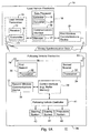
- FIG. 1A illustrates a system 11 for tracking a path or position (or position and heading) of a lead vehicle.
- the following vehicle is synonymous with the term trailing vehicle as used herein.
- the system 11 comprises lead vehicle electronics 10 that communicates with following vehicle electronics 26 via an electromagnetic signal (e.g., radio frequency signal or microwave signal).
- an electromagnetic signal e.g., radio frequency signal or microwave signal.
- the lead vehicle electronics 10 comprises a receiver 12 and a transmitter 14 coupled to a data processor 16.
- the combination of the receiver 12 and the transmitter 14 may be referred to as lead vehicle transceiver 15.
- a first wireless communications device 24 is coupled to the data processor 16.
- the data processor 16 may comprise an estimator 18, a converter 20, a manager 21, and a communications interface 22.
- the following vehicle electronics 26 comprises a first beacon 30 and a second beacon 34 that are separated by a known separation distance 28.
- the first beacon 30 and second beacon 34 each comprise a transceiver 32.
- the vehicle electronics 26 includes a second wireless communications device 36 coupled to a control interface 38.
- the control interface 38 is coupled to a following vehicle controller 41.
- the following vehicle controller 41 may send control signals to one or more of the following devices via a logical data path or a physical data path (e.g., a databus): a steering system 42, a braking system 44, and propulsion system 46.
- the steering system 42 may comprise an electrically controlled hydraulic steering system, an electrically driven rack-and-pinion steering, an Ackerman steering system, or another steering system.
- the braking system 44 may comprise an electrically controlled hydraulic braking system, or another electrically controlled friction braking system.
- the propulsion system 46 may comprise an internal combustion engine, an internal combustion engine-electric hybrid system, an electric drive system, or the like.
- the following vehicle controller 41 may generate control signals for the steering system 42, a braking system 44 (if present), and a propulsion system 46 that are consistent with tracking a path plan, provided by the path planning module.
- the control signals may comprise a steering control signal or data message that is time dependent and defines a steering angle of the steering shaft; a braking control signal or data message that defines the amount of deceleration, hydraulic pressure, or braking friction applied to brakes; a propulsion control signal or data message that controls a throttle setting, a fuel flow, a fuel injection system, vehicular speed or vehicular acceleration. If the vehicle is propelled by an electric drive or motor, the propulsion control signal or data message may control electrical energy, electrical current, or electrical voltage to the electric drive or motor.
- the data processor 16 or estimator 18 estimates a relative position or location (or location and heading) of the following vehicle with respect to the lead vehicle based on the elapsed propagation time associated with an outgoing propagation path to the following vehicle electronics 26, an incoming propagation path from the following vehicle electronics 26, or both.
- the data processor 16 may be configured in several different ways. In a first configuration of the data processor, the data processor 16 may process the elapsed propagation times directly, rather than converting them to corresponding distances. Under the first configuration, the converter 20 is not used and may be deleted. In a second configuration, of the data processor 16, the converter 20 is used.
- the manager 21 manages the relationship between a first propagation delay and the second propagation delay (e.g., under a first configuration), or between the first distance and the second distance (e.g., under a second configuration).
- the first propagation delay is the delay associated with propagation of the electromagnetic signal between the transmitter 14 (e.g., the lead vehicle antenna 77) and the first beacon 130 (e.g., the first following vehicle antenna 79)
- the second propagation delay is the delay associated with the propagation of the electromagnetic signal between the transmitter 14 (e.g., the lead vehicle antenna 77) and the second beacon 134 (e.g., the second following vehicle antenna 81).
- the first propagation delay is generally proportional to a first distance between a first following vehicle antenna 79 and a lead vehicle antenna 77; the second propagation delay is generally proportional to a second distance between the second following vehicle 81 antenna 79 and a lead vehicle antenna 77.
- the communications interface 22 supports communications of the distance data, temporal data, or relative position data (e.g., heading and spatial separation) to the following vehicle electronics 26 via a first wireless communications devices 24 and a second wireless communications device 36 associated with the lead vehicle and the following vehicle, respectively.
- the control interface 38 receives the distance data, temporal data, or relative position data and provides it to the following vehicle controller 41.
- the following vehicle controller 41 may direct the vehicle to maintain a safe or uniform distance and/or heading from the lead vehicle or to track the path of the lead vehicle.
- the vehicle controller 41 may command the steering system 42 to track the path of the lead vehicle and the propulsion system 46 to track the acceleration, speed or velocity of the lead vehicle.
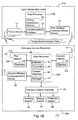
- the vehicle tracking system 111 of FIG. 1B differs from the vehicle tracking system 11 of FIG. 1A in that the vehicle tracking system 111 of FIG. 1B is generally configured to use one-way propagation time from the transmitter 14 to each beacon (130, 134), as opposed to a two-way or round-trip propagation time between the transceiver 15 and the beacons (30, 34).
- the vehicle tracking system 111 of FIG. 1B is generally configured to use one-way propagation time from the transmitter 14 to each beacon (130, 134), as opposed to a two-way or round-trip propagation time between the transceiver 15 and the beacons (30, 34).
- Like reference numbers in FIG. 1A and FIG. 1B indicate like elements.
- the lead vehicle electronics 210 comprises a data processor 116.
- the data processor 116 comprises a timing coordination module 19 and a communications interface 22.
- the timing coordination module 19 transmits or exchanges timing synchronization data or timing data between the lead vehicle electronics 210 and the following vehicle electronics 226 to support knowledge of the transmission time at the following vehicle electronics 226.
- the first wireless communications device 24 and the second wireless communications device 36 may communicate to exchange timing synchronization data or transmission time data for the coordination of clock or timing signals of the lead vehicle electronics 210 and the following vehicle electronics 226.
- the following vehicle electronics 226 comprises a first beacon 130 and a second beacon 134.
- the first beacon 130 and the second beacon 134 each include a receiver 132, which is coupled to the data processor 216.
- the data processor 216 comprises an estimator 18, a converter 20, a control interface 38, and a manager 21.
- the system 11 of FIG. 1B estimates the first propagation delay and the second propagation delay at the data processor 216 of the following vehicle electronics 226.
- the data processor 216 may use the first propagation delay and the second propagation delay (or data or signals, representative thereof) directly to control data from the following vehicle controller 41
- the converter 20 may convert the first propagation delay and the second propagation delay into a first distance and a second distance, respectively for subsequent processing into control data.
- the manager 21 can use temporal data or distance data to develop management or control data for the following vehicle controller 41.
- the known separation distance 28 refers to a separation (e.g., horizontal separation) between following vehicle antennas 79 associated with the beacons (30 and 34, or 130 and 134). Further, by measuring the range from the antennas 79 associated with the beacons of the following vehicle electronics 226 to an antenna 77 associated with the transmitter 14 or lead vehicle transceiver 15 of the lead vehicle electronics 210, the distance and angle of the leading vehicle relative to the following vehicle can be determined.
- the ranging accuracy (r) for distance may provide an accuracy of within a range from 3 centimeters to 1 centimeter, or less, for example.
- a the angular estimation accuracy in radians
- r the range accuracy
- s the known separation distance 28.
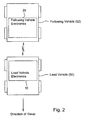
- FIG. 2 shows a following vehicle 52 tracking a lead path or lead position (or lead position and heading) of a lead vehicle 50.
- the following vehicle 52 may follow or trace the path (or lead position and heading) of the lead vehicle 50 with an offset or delay in time based on one or more of the following: (1) the spatial separation between the lead vehicle 50 and the following vehicle 52, (2) the relative speed or relative velocity between the lead vehicle and following vehicle 52, and (3) the relative acceleration or deceleration between the lead vehicle and the following vehicle 52.
- the following vehicle 52 has a following path or a following position.
- Like reference numbers in FIG. 1A and FIG. 2 indicate like elements.
- the lead vehicle electronics 10 may determine the relative positions (e.g., spatial separation and vehicular headings) of the lead vehicle 50 and the following vehicle 52. If the lead vehicle electronics 10 is associated with a location determining receiver (e.g., Global Positioning system receiver with differential correction), the absolute or real world coordinates of the lead vehicle 50 may be first determined and then the absolute or real world coordinates of the following vehicle 52 may be derived by the relative positions of the lead vehicle 50 and the following vehicle 52. However, it may be sufficient to use the relative coordinates and positions between the vehicles for vehicular control and guidance (e.g., collision avoidance).
- a location determining receiver e.g., Global Positioning system receiver with differential correction
- the absolute or real world coordinates of the lead vehicle 50 may be first determined and then the absolute or real world coordinates of the following vehicle 52 may be derived by the relative positions of the lead vehicle 50 and the following vehicle 52.
- FIG. 3A shows a method for following a vehicle tracking a lead path or lead position of a lead vehicle. The method of FIG. 3A begins in step S100.
- a transmitter 14 at a lead vehicle transmits a first transmission signal (e.g., an identifiable pulse) at a transmission time toward a first beacon (30 or 130) and a second beacon (34 or 134) associated with a following vehicle.
- the first transmission signal may be modulated with a coded signal (e.g., pseudo-random noise code), a pulse, a pulse train, phase shift keying, amplitude shift keying, frequency shift keying, pulse width modulation, pulse amplitude modulation, pulse phase modulation, or any other suitable modulation scheme.
- a coded signal e.g., pseudo-random noise code
- a data processor (16 or 216) or estimator 18 determines a first propagation time associated with the first transmission and the first beacon (30 or 130) and a second propagation time associated with the first transmission and the second beacon (34 or 134).
- the determination of the first propagation time and the second propagation time may be carried out in accordance with various techniques, which may be applied alternately or cumulative.
- the first propagation time comprises a propagation time between the transmission time at the transmitter 14 and a reception time at the first beacon (30 or 130) (e.g., for a unidirectional or one-way path)
- the second propagation time comprises a propagation time between the transmission time at the transmitter 14 and a reception time at the second beacon (34 or 134) (e.g., for a unidirectional or one-way path).
- the first propagation time comprise a first aggregate elapsed time between the transmission time of the first transmission signal to a first beacon 30 and a return signal from the first beacon 30 to the lead vehicle electronics 10.
- the second propagation time comprises a second aggregate elapsed time between the transmission time of the first transmission signal to a second beacon 34 and a return signal from the second beacon 34 to the lead vehicle electronics 10.
- the transmission time of the first transmission (e.g., identifiable pulse) is provided to or known by the estimator 18 or data processor 16.
- the relative separation distance between the lead vehicle and the following or trailing vehicle may be determined as well as the relative heading between the lead vehicle and the trailing or following vehicle. The relative separation is actually dependent upon where the antennas (77, 79) are mounted on the lead and following vehicles, and on any spatial offset or temporal offset, that may be required to obtain the relative physical distance (e.g., front to rear spacing or bumper-to-bumper spacing) of the vehicles.
- a clock synchronization signal or timing synchronization data may be shared between the lead vehicle electronics (10 or 210) and the following vehicle electronics (26 or 226) to coordinate the timing (and minimize phase differences) in the locally generated precision clock signals.
- the lead vehicle electronics 10, the following vehicle electronics 20, or both may comprise precision clocks, precision oscillators, or waveform generators with sufficient frequency stability to product accurate ranging measurements.
- the clock synchronization or transmission time data may be distributed or transmitted wirelessly prior to, during, or after the first transmission.
- the estimator 18 or data processor 16 may be co-located with the transmitter 14 and the transmitter 14 may be associated with a receiver 12 or transceiver 15 for receiving a return signal from one or more beacons based on the first transmission signal.
- a following vehicle controller 41 controls a heading, or a position, or both a heading and position of the following vehicle to maintain a first propagation time equal to a second propagation time, or a first propagation time that deviates from the second propagation time by a predetermined maximum amount.
- following vehicle controller 41 controls a heading of the following vehicle such that the first propagation time substantially equal to a second propagation time.
- the first propagation time and the second propagation time are representative of or proportional to the first distance and the second distance.
- the first distance refers to a distance between a following vehicle antenna 79 at the first beacon (30 or 130) and lead vehicle antenna 77.
- the second distance refers to a distance between a second following vehicle antenna 81 at the second beacon (34 or 134) and the lead vehicle antenna 77.
- the converter 20 or data processor 16 converts the first propagation time and the second propagation time into a first distance and a second distance, respectively, prior to processing by the following vehicle controller 41 such that representative distances of the propagation times are processed.
- FIG. 3B shows a method for a trailing vehicle to track a lead path or lead position of a lead vehicle.
- the method of FIG. 3B describes a procedure in which a unidirectional transmission flows from the transmitter 40 to the first beacon 130, from the first beacon 130 to the second beacon 134, and from the second beacon 134 to the receiver 12.
- the method of FIG. 3B begins in step S200.
- step S200 a transmitter 14 at lead vehicle transmits a first transmission signal toward a first beacon 30 associated with a following vehicle or trailing vehicle.
- the first beacon 30 and a second beacon 34 communicate with each other.
- the first beacon 30 and the second beacon 34 may be spaced apart by a known distance or there may be a generally fixed communication delay associated with communications (e.g., over wireless, wireline, or transmission line) between the beacons (30, 34).
- the first beacon 30 and second beacon 34 may communicate via a transmission line, coaxial cable, or another configuration where the propagation delay associated with the transmission line is measured or predetermined for a given length of transmission line.
- the first beacon 30 communicates one or more of the following: (1) the transmission time from the transmitter 14, (2) the receipt time at the transceiver 32, (3) both the transmission time from the transmitter 14 and the receipt time at the transceiver 32, and (4) a difference between the transmission time and the receipt time to the second beacon 34.
- the lead vehicle electronics 10 and the following vehicle electronics 26 may require precision oscillators or clocks that are synchronized with the exchange or synchronization data to properly evaluate and judge the foregoing transmission time, receipt time, time difference, and any other propagation time between the following vehicle electronics 26 and the lead vehicle electronics 10.
- step S204 the second beacon 34 transmits a second transmission signal to the lead vehicle.
- the receiver 12 or transceiver 15 receives the second transmission signal and provides the demodulated or decoded signal to the data processor 16
- step S206 the data processor 16 or estimator 18 determines a first elapsed time between the transmission of the first transmission signal to the first beacon 30.
- step S208 the data processor 16 or estimator 18 determines a second elapsed time between the transmission of the second transmission signal from the second beacon 34 to the lead vehicle.
- step S21 the data processor 16 or converter 20 converts the first elapsed time into a first distance (e.g., first distance 55) between the transmitter 14 and the first beacon 30.
- a first distance e.g., first distance 55
- step S212 the data processor 16 or converter 20 converts the second elapsed time into a second distance (e.g., second distance 57) between the transmitter 14 and the second beacon 34.
- a second distance e.g., second distance 57
- step S310 the data processor 16 or a following vehicle controller 41 controls at least one of a heading and a position of the following vehicle to maintain a first distance substantially equal to a second distance.
- the first distance means the displacement between lead vehicle antenna 77 and first following vehicle antenna 79 of the first beacons 30.
- the second distance means the displacement between the lead vehicle antenna 77 and the second following vehicle antenna 81 of the second beacon 34.
- FIG. 4 shows a method for following vehicle tracking a lead path or lead position of a lead vehicle. The method of FIG. 4 starts in step S300.
- step S300 a transmitter 14 at a lead vehicle transmits a first transmission signal toward a first beacon 30 and a second beacon 34 associated with a following vehicle.
- a data processor 16 or estimator 18 determines a first aggregate elapsed time between transmission of the first transmission signal to a first beacon 30 and a return signal from the first beacon 30 to the lead vehicle. Prior to the determination of the first aggregate elapsed time, the receiver 12 or the transceiver 15 may receive the return signal for determination of the first aggregate elapsed time by the estimator 18 or the data processor 16.
- step S304 the data processor 16 or estimator 18 determines a second aggregate elapsed time between the transmission of the first transmission signal to a second beacon 34 and a return signal from the second beacon 34 to the lead vehicle.
- the receiver 12 or the transceiver 15 may receive the return signal for determination of the second aggregate elapsed time by the estimator 18 or the data processor 16.
- step S306 the data processor 16 or converter 20 converts the first aggregate elapsed time into a first distance between the transmitter 14 and the first beacon 30.
- the first distance refers to a distance between a following vehicle antenna 79 at the first beacon (30 or 130) and lead vehicle antenna 77.
- step S308 the data processor 16 or converter 20 converts the second aggregate elapsed time into a second distance (e.g., second distance 57) between the transmitter 14 and the second beacon 34.
- the second distance refers to a distance between a second following vehicle antenna 81 at the second beacon (34 or 134) and the lead vehicle antenna 77.
- step S310 the vehicle controller 41 controls a heading of the following vehicle to maintain a first distance substantially equal to a second distance.
- FIG. 5 shows a method for following vehicle tracking a lead path or lead position of a lead vehicle. Like reference numbers in FIG. 4 and FIG. 5 indicate like steps or procedures. The method of FIG. 5 starts in step S300.
- step S300 a transmitter 14 at a lead vehicle transmits a first transmission signal toward a first beacon 30 and a second beacon 34 associated with a following vehicle.
- a data processor 16 or estimator 18 determines a first aggregate elapsed time between transmission of the first transmission signal to a first beacon 30 and a turn signal from the first beacon 30 to the lead vehicle.
- step S304 the data processor 16 or estimator 18 determines a second aggregate elapsed time between the transmission of the first transmission signal to a first beacon 30 and a return signal from the first beacon 30 to the lead vehicle.
- step S306 the data processor 16 or converter 20 converts the first aggregate elapsed time into a first distance between the transmitter 14 and the first beacon 30.
- step S308 the data processor 16 or converter 20 converts the second aggregate elapsed time into a second distance between the transmitter 14 and the second beacon 34.
- a first location-determining receiver (e.g., 60 in FIG. 10 ) of the lead vehicle determines a global position of the lead vehicle based at least partially on the reception of a group of satellite signals.
- a second location-determining receiver determines a global position of the following vehicle based at least partially on a reception of a group of satellite signals.
- a recorder or data storage device (e.g., 63 in FIG. 10 ) records a registration of a lead vehicle with the respective global position.
- step S322 the vehicle controller 41 controls the following heading of the following vehicle to match that of the lead vehicle at the respective global position provided that the leading vehicle and following vehicle maintain a minimum separation.
- the following vehicle may track the heading of the leading vehicle virtually instantaneously.
- the following vehicle may delay its heading tracking based on the separation between the vehicles, velocity, and acceleration. If the lead vehicle and the following vehicle are both equipped with the first location-determining receiver 60 and the second location-determining receiver 61, respectively, the following location of the following vehicle may be associated with the same or substantially the same heading as the leading vehicle when the leading vehicle was at the following location.
- the lead vehicle may store its heading information and associate it with its instantaneous location in the data storage device 63 or transmit pairs of heading information and corresponding location data to the following vehicle via a wireless communications channel (e.g., via the first wireless communications device 24 and the second wireless communications device 36).
- a wireless communications channel e.g., via the first wireless communications device 24 and the second wireless communications device 36.
- FIG. 6 shows a plan view of a lead vehicle 50 and a following vehicle 52 separated by a separation distance 56.
- the transmitter 14 of the lead vehicle 50 and the first beacon 30 is associated with a first distance 55.
- the first distance 55 extends between the lead vehicle transmitter antenna 77 and the first follower vehicle antenna 79 of the first beacon 30.
- the transmitter 14 of the lead vehicle 50 and the second beacon 34 is associated with a second distance 57.
- the second distance 57 extends between the lead vehicle antenna 77 and the second follower vehicle antenna 81 of the second beacon 34.
- the points associated with each end of the first distance 55 and the second distance 57 comprise antennas or antenna elements associated with the lead vehicle electronics 10 and the following vehicle electronics 26.
- the first distance 55 and the second distance 57 may form an angle with two generally equal sides or legs such that the following vehicle 52 tracks the leading vehicle.
- this tracking mode may present problems in maneuvering around obstacles or in sharp curves. For example, the leading vehicle may maneuver around a sharp turn or obstacle, but the following vehicle 52 may strike the obstacle if the first distance 55 and the second distance 57 are kept substantially equal at all times.
- FIG. 7 illustrates a second tracking mode where, the first distance 155 and the second distance 157 are allowed to differ by a maximum amount to negotiate around a turn, an obstacle, or otherwise as the context requires.
- the inner leg e.g., the first distance 155) that is radially closest to a center point of turn has shorter length than an other leg that is radially farthest from the counterpoint of turn. If the vehicles (50, 52) turn in the opposite direction to that shown in FIG. 7 the inner leg may comprise the other leg (e.g., the second distance 157).
- the separation distance 156 may be set to maintain a minimum clearance between the lead vehicle 50 and the following vehicle 52 when the vehicles (50, 52) are engaged in a turn.
- the separation distance 156 is proportional to the first distance and the second distance.
- FIG. 8 illustrates a train or convoy of vehicles. Like reference numbers in FIG. 7 and FIG. 8 indicate like elements.
- the train of vehicles comprises a lead vehicle 50, one or more intermediate vehicles 800, and a following vehicle 52.
- a train means a line or file of vehicles that may proceed together, but are not necessarily mechanically coupled together.
- the lead vehicle 50 and the following vehicle 52 have been described in conjunction with FIG. 6 and 7 , for example.
- Each intermediate 800 vehicle comprises intermediate vehicle electronics 802.
- the intermediate vehicle electronics 802 is essentially a combination of the lead vehicle electronics 10 and the following vehicle electronics 26.
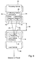
- FIG. 9 shows the intermediate vehicle electronics in greater detail.
- Like reference numbers in FIG. 9 and FIG. 1A indicate like elements. The elements were previously described in conjunction with FIG. 1A , for example.
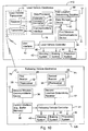
- the system for following a lead vehicle in FIG. 10 is similar to the system for following a lead vehicle in FIG. 1A , except additional equipment is included in the lead vehicle electronics 110 of FIG. 10 and the following vehicle electronics 126 of FIG. 10 .
- Like reference numbers in FIG. 1A and FIG. 10 indicate like elements.
- the lead vehicle electronics 110 comprises a first location-determining receiver 60, a user interface 62, a data storage device 63, a lead vehicle controller 40, a steering system 42, a braking system 44, and a propulsion system 46.
- the following vehicle electronics 126 comprises a second location determining receiver 61, a following vehicle controller 41, a steering system 42, a braking system 44, and a propulsion system 46.
- the location determining receivers each may comprise a Global Positioning System (GPS) receiver with or without differential correction or another location determining receiver that relies at least partially upon the reception of satellite transmissions to determine location (e.g., coordinates), velocity, heading, or other position information.
- GPS Global Positioning System
- the data storage device 63 is arranged to record a registration of a leading heading of the lead vehicle with the respective global position.
- the data storage device 63 may receive location data from the first location-determining receiver 60 and control data from the lead vehicle controller 40.
- the data storage device 63 may be associated with a format or registration module for temporally aligning the received location data and the received control data.
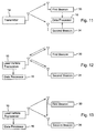
- FIG. 11 and FIG. 13 indicate various illustrative possibilities for communications between the lead vehicle and the trailing vehicle. Like reference numbers in the previous drawings represent like elements for FIG. 11 through 13 , inclusive.
- the first and second communications links may be established on different physical or virtual channels.
- the first communications link may be assigned to certain time slots (or generally orthogonal codes) of a electromagnetic signal and the second communications link may be assigned to other time slots (or other generally orthogonal codes) of the co-frequency electromagnetic signal.
- different frequencies may be used for the first communications link and the second communications link to permit simultaneous communications.
- the communications links may be one-way or two-way. If a one-way link is used the first beacon 30 and the second beacon 34 may be equipped with a data processor 16 for estimating a first distance (e.g., first distance 55 in FIG. 6 ) and a second distance (e.g., second distance 57 in FIG. 6 ) to keep the distances substantially equal or within a defined limit of substantially equal to accommodate turns, obstacle avoidance, and the like. Further, the one-way link may be associated with a one-way propagation time between the lead vehicle 150 and the following vehicle 52. If a two-way link is used, a two-way propagation time may be used to determine the first distance and the second distance at the lead vehicle.
- a first distance e.g., first distance 55 in FIG. 6
- a second distance e.g., second distance 57 in FIG. 6
- first and second communications links may be established on differential physical or virtual channels.
- the first communications link may be assigned to certain time slots (or generally orthogonal codes) of a electromagnetic signal and the second communications link may be assigned to other time slots (or other generally orthogonal codes) of the co-frequency electromagnetic signal.
- different frequencies may be used for the first communications link and the second communications link to permit simultaneous communications.
- FIG. 13 is similar to the configuration of FIG. 12 .
- a first transmission e.g., first one-way transmission
- a second transmission e.g., a second one-way transmission
- a third transmission is from the second beacon 34 to the lead vehicle transceiver 15.
- the beacons in the configuration of FIG. 13 may be self-configuring upon set-up by sharing, transmitting or determining relative orientation to each other.
Landscapes
- Engineering & Computer Science (AREA)
- Radar, Positioning & Navigation (AREA)
- Remote Sensing (AREA)
- Aviation & Aerospace Engineering (AREA)
- Physics & Mathematics (AREA)
- General Physics & Mathematics (AREA)
- Automation & Control Theory (AREA)
- Traffic Control Systems (AREA)
Claims (10)
- Procédé pour suivre un véhicule de tête (10) avec un véhicule suiveur (26), le procédé consistant à :émettre un premier signal d'émission vers une première balise (30) et une seconde balise (34) associée à un véhicule suiveur (26) ;déterminer un premier temps de propagation associé à la première émission et à la première balise (30) et un second temps de propagation associé à la première émission et à la seconde balise (34) ;commander un cap du véhicule suiveur afin de maintenir un premier temps de propagation sensiblement égal au second temps de propagation sur un segment de trajectoire droit ou linéaire ;caractérisé en ce que la commande comprend en outre la commande d'un cap du véhicule suiveur afin de maintenir une première distance qui s'écarte de la seconde distance d'une quantité maximale prédéterminée sur un trajet incurvé ou un virage.
- Procédé selon la revendication 1, dans lequel le premier temps de propagation comprend un temps de propagation entre l'instant d'émission par l'émetteur (14) et un instant de réception par la première balise (30), et dans lequel le second temps de propagation comprend un temps de propagation entre l'instant d'émission par l'émetteur (14) et un instant de réception par la seconde balise (34).
- Procédé selon la revendication 1, dans lequel le premier temps de propagation comprend un premier temps écoulé cumulatif entre l'instant d'émission du premier signal d'émission vers une première balise (30) et un signal de retour de la première balise (30) au véhicule de tête (10), le second temps de propagation comprend un second temps écoulé cumulatif entre l'instant d'émission du premier signal d'émission vers la seconde balise (34) et un signal de retour de la seconde balise (34) au véhicule de tête (10).
- Procédé selon la revendication 1, comprenant en outre :la conversion du premier temps de propagation et du second temps de propagation en une première distance et en une seconde distance, respectivement, avant le traitement effectué par l'unité de commande du véhicule suiveur.
- Procédé selon l'une des revendications 1 à 4, consistant en outre à :la première balise et la seconde balise étant séparées d'une distance connue ;convertir un premier temps écoulé cumulatif entre l'émission du premier signal d'émission vers une première balise et un signal de retour de la première balise au véhicule de tête en une première distance entre l'émetteur et la première balise ;convertir un second temps écoulé cumulatif entre l'émission du premier signal d'émission vers une seconde balise et un signal de retour de la seconde balise au véhicule de tête en une seconde distance entre l'émetteur et la seconde balise ; etcommander un cap du véhicule suiveur afin de maintenir une première distance sensiblement égale à une seconde distance.
- Procédé selon l'une des revendications 1 à 5, consistant en outre à :commander une vitesse du véhicule suiveur afin de maintenir au moins l'une d'une première distance souhaitée et d'une seconde distance souhaitée.
- Procédé selon la revendication 5, dans lequel la commande comprend en outre la poursuite d'un cap de tête du véhicule de tête avec un cap suiveur d'un véhicule suiveur et avec un retard basé sur au moins l'une de la vitesse et de l'accélération du véhicule de tête.
- Procédé selon la revendication 5, consistant en outre à :déterminer une position globale du véhicule de tête sur la base au moins en partie de la réception d'un groupe de signaux de satellites ;déterminer une position globale du véhicule suiveur sur la base au moins en partie de la réception d'un groupe de signaux de satellites ;enregistrer un alignement d'un cap de tête du véhicule de tête avec la position globale respective ;commander le cap suiveur du véhicule suiveur de façon à ce qu'il concorde avec celui du véhicule de tête à la position globale respective sous réserve que le véhicule de tête et le véhicule suiveur conservent une séparation minimale.
- Procédé selon l'une des revendications 1 à 8, consistant en outre à :communiquer entre la première balise et une seconde balise espacée de la première balise d'une distance connue ;déterminer un premier temps écoulé depuis l'émission du premier signal d'émission vers une première balise ; déterminer un second temps écoulé depuis l'émission du second signal d'émission de la seconde balise vers le véhicule de tête ;convertir le premier temps écoulé en une première distance entre l'émetteur et la première balise ; convertir le second temps écoulé en une seconde distance entre l'émetteur et la seconde balise ; et commander un cap du véhicule suiveur afin de maintenir une première distance sensiblement égale à une seconde distance.
- Système pour suivre un véhicule de tête avec un véhicule suiveur, le système pouvant être mis en fonctionnement conformément à un procédé selon l'une des revendications 1 à 9.
Applications Claiming Priority (1)
| Application Number | Priority Date | Filing Date | Title |
|---|---|---|---|
| US11/095,318 US7593811B2 (en) | 2005-03-31 | 2005-03-31 | Method and system for following a lead vehicle |
Publications (3)
| Publication Number | Publication Date |
|---|---|
| EP1708065A2 EP1708065A2 (fr) | 2006-10-04 |
| EP1708065A3 EP1708065A3 (fr) | 2007-05-16 |
| EP1708065B1 true EP1708065B1 (fr) | 2010-01-13 |
Family
ID=36609561
Family Applications (1)
| Application Number | Title | Priority Date | Filing Date |
|---|---|---|---|
| EP06111003A Ceased EP1708065B1 (fr) | 2005-03-31 | 2006-03-13 | Procédé et système de suivi d'un véhicule de tête |
Country Status (3)
| Country | Link |
|---|---|
| US (1) | US7593811B2 (fr) |
| EP (1) | EP1708065B1 (fr) |
| DE (1) | DE602006011665D1 (fr) |
Families Citing this family (68)
| Publication number | Priority date | Publication date | Assignee | Title |
|---|---|---|---|---|
| US7653483B2 (en) * | 2005-03-31 | 2010-01-26 | Deere & Company | System and method for determining a position of a vehicle |
| US20070233337A1 (en) * | 2005-09-14 | 2007-10-04 | Plishner Paul J | Semi-autonomous guidance system for a vehicle |
| FI120191B (fi) * | 2005-10-03 | 2009-07-31 | Sandvik Tamrock Oy | Menetelmä kaivosajoneuvojen ajamiseksi kaivoksessa ja kuljetusjärjestelmä |
| JP2007241726A (ja) * | 2006-03-09 | 2007-09-20 | Denso Corp | 運転支援システム、送信装置及び受信装置 |
| DE102006019841B3 (de) * | 2006-04-28 | 2007-12-20 | Moba-Mobile Automation Ag | Vorrichtung und Verfahren zur Ermittlung der Position einer Straßenwalze relativ zu einem Straßenfertiger |
| EP2006448A1 (fr) * | 2007-06-21 | 2008-12-24 | Leica Geosystems AG | Train de finisseuses pour la fabrication d'une couche de revêtement routier en béton ou en asphalte |
| US8326473B2 (en) * | 2007-07-06 | 2012-12-04 | University of Pittsburgh—of the Commonwealth System of Higher Education | Powered vehicle convoying systems and methods of convoying powered vehicles |
| US8170756B2 (en) * | 2007-08-30 | 2012-05-01 | Caterpillar Inc. | Excavating system utilizing machine-to-machine communication |
| US20090062974A1 (en) * | 2007-09-03 | 2009-03-05 | Junichi Tamamoto | Autonomous Mobile Robot System |
| EP2055835A1 (fr) * | 2007-10-30 | 2009-05-06 | Saab Ab | Procédé et agencement pour déterminer la position de véhicules relatifs les uns des autres |
| US8285456B2 (en) * | 2008-02-29 | 2012-10-09 | Caterpillar Inc. | System for controlling a multimachine caravan |
| US8160765B2 (en) * | 2008-03-03 | 2012-04-17 | Cnh America Llc | Method and system for coordinated vehicle control with wireless communication |
| US20100082179A1 (en) * | 2008-09-29 | 2010-04-01 | David Kronenberg | Methods for Linking Motor Vehicles to Reduce Aerodynamic Drag and Improve Fuel Economy |
| IL200921A (en) * | 2009-09-14 | 2016-05-31 | Israel Aerospace Ind Ltd | A robotic carry system for infantry and useful methods for the above purpose |
| EP2390744B1 (fr) * | 2010-05-31 | 2012-11-14 | Volvo Car Corporation | Système de contrôle pour le voyage dans des véhicules en groupe |
| US8496078B2 (en) | 2011-01-29 | 2013-07-30 | GM Global Technology Operations LLC | Semi-autonomous vehicle providing cargo space |
| US8627908B2 (en) | 2011-01-29 | 2014-01-14 | GM Global Technology Operations LLC | Semi-autonomous vehicle providing an auxiliary power supply |
| AU2011359328B2 (en) | 2011-02-18 | 2015-06-11 | Cnh Industrial America Llc | System and method for trajectory control of a transport vehicle used with a harvester |
| WO2013006826A2 (fr) * | 2011-07-06 | 2013-01-10 | Peloton Technology Inc. | Systèmes et procédés pour convoyage de véhicules semi-autonome |
| US10520952B1 (en) | 2011-07-06 | 2019-12-31 | Peloton Technology, Inc. | Devices, systems, and methods for transmitting vehicle data |
| WO2014145918A1 (fr) | 2013-03-15 | 2014-09-18 | Peloton Technology, Inc. | Systèmes et procédés de circulation en peloton de véhicules |
| US11614752B2 (en) * | 2011-07-06 | 2023-03-28 | Peloton Technology, Inc. | Vehicle platooning systems and methods |
| US20170242443A1 (en) | 2015-11-02 | 2017-08-24 | Peloton Technology, Inc. | Gap measurement for vehicle convoying |
| US11334092B2 (en) | 2011-07-06 | 2022-05-17 | Peloton Technology, Inc. | Devices, systems, and methods for transmitting vehicle data |
| US10520581B2 (en) * | 2011-07-06 | 2019-12-31 | Peloton Technology, Inc. | Sensor fusion for autonomous or partially autonomous vehicle control |
| US9582006B2 (en) | 2011-07-06 | 2017-02-28 | Peloton Technology, Inc. | Systems and methods for semi-autonomous convoying of vehicles |
| US9026367B2 (en) * | 2012-06-27 | 2015-05-05 | Microsoft Technology Licensing, Llc | Dynamic destination navigation system |
| FR2996646B1 (fr) * | 2012-10-09 | 2014-12-26 | Thales Sa | Systeme de guidage de vehicule et procede correspondant |
| US8761989B1 (en) | 2012-12-18 | 2014-06-24 | Jervis B. Webb Company | Method of material handling with automatic guided vehicles |
| US11294396B2 (en) * | 2013-03-15 | 2022-04-05 | Peloton Technology, Inc. | System and method for implementing pre-cognition braking and/or avoiding or mitigation risks among platooning vehicles |
| US20180210463A1 (en) | 2013-03-15 | 2018-07-26 | Peloton Technology, Inc. | System and method for implementing pre-cognition braking and/or avoiding or mitigation risks among platooning vehicles |
| US9014902B1 (en) | 2014-02-21 | 2015-04-21 | Jervis B. Webb Company | Method of material handling with automatic guided vehicles |
| FR3018941B1 (fr) * | 2014-03-21 | 2017-07-07 | Thales Sa | Pilotage de vehicules en convoi |
| US9529364B2 (en) | 2014-03-24 | 2016-12-27 | Cnh Industrial America Llc | System for coordinating agricultural vehicle control for loading a truck |
| US9296411B2 (en) * | 2014-08-26 | 2016-03-29 | Cnh Industrial America Llc | Method and system for controlling a vehicle to a moving point |
| US10965755B2 (en) | 2014-11-12 | 2021-03-30 | Westinghouse Air Brake Technologies Corporation | Communication system and method |
| US9384666B1 (en) * | 2015-02-01 | 2016-07-05 | Thomas Danaher Harvey | Methods to operate autonomous vehicles to pilot vehicles in groups or convoys |
| US10373378B2 (en) | 2015-06-26 | 2019-08-06 | Paccar Inc | Augmented reality system for vehicle blind spot prevention |
| US10712748B2 (en) | 2015-08-26 | 2020-07-14 | Peloton Technology, Inc. | Devices, systems, and methods for generating travel forecasts for vehicle pairing |
| WO2017043921A1 (fr) * | 2015-09-10 | 2017-03-16 | 엘지전자 주식회사 | Procédé et dispositif pour réaliser une communication avec un terminal virtuel dans un système de communication sans fil |
| EP3380905B1 (fr) * | 2015-11-12 | 2021-02-17 | Boyle, Norman | Système véhiculaire de signalisation routière sans conducteur |
| WO2017138920A1 (fr) * | 2016-02-09 | 2017-08-17 | Ford Global Technologies, Llc | Appareil et procédé pour un véhicule autonome pour suivre un objet |
| FR3048148B1 (fr) * | 2016-02-22 | 2018-12-07 | Universite Blaise Pascal | Localisation d'une cible pour vehicule suiveur |
| WO2017210200A1 (fr) | 2016-05-31 | 2017-12-07 | Peloton Technology, Inc. | Machine à états pour régulateur de peloton |
| JP6690056B2 (ja) | 2016-08-22 | 2020-04-28 | ぺロトン テクノロジー インコーポレイテッド | 自動連続車両の制御システムアーキテクチャ |
| US10369998B2 (en) | 2016-08-22 | 2019-08-06 | Peloton Technology, Inc. | Dynamic gap control for automated driving |
| US10849081B2 (en) * | 2016-09-16 | 2020-11-24 | Qualcomm Incorporated | Synchronized radio transmission for vehicle platooning |
| CN107121989B (zh) * | 2017-05-17 | 2020-09-15 | 深圳市元时科技有限公司 | 一种无线电磁波跟随的方法及系统 |
| JP6813433B2 (ja) * | 2017-06-13 | 2021-01-13 | 日立オートモティブシステムズ株式会社 | 車両運動制御装置、車両運動制御方法および車両運動制御システム |
| JP7031212B2 (ja) * | 2017-10-12 | 2022-03-08 | トヨタ自動車株式会社 | 移動支援システムおよび移動支援方法 |
| CN109933093A (zh) * | 2017-12-18 | 2019-06-25 | 华创车电技术中心股份有限公司 | 自动追随装置与自动追随系统 |
| JP6989429B2 (ja) * | 2018-03-28 | 2022-01-05 | 株式会社東芝 | 隊列走行運用システムおよび隊列走行運用方法 |
| US10899323B2 (en) | 2018-07-08 | 2021-01-26 | Peloton Technology, Inc. | Devices, systems, and methods for vehicle braking |
| KR102626835B1 (ko) * | 2018-10-08 | 2024-01-18 | 삼성전자주식회사 | 경로를 결정하는 방법 및 장치 |
| US10762791B2 (en) | 2018-10-29 | 2020-09-01 | Peloton Technology, Inc. | Systems and methods for managing communications between vehicles |
| US10401870B1 (en) * | 2018-11-15 | 2019-09-03 | Grey Orange Pte. Ltd. | System and method for handling items using movable-bots |
| AU2019100368B4 (en) | 2019-01-25 | 2019-11-28 | Norman BOYLE | A driverless impact attenuating traffic management vehicle |
| WO2020165824A1 (fr) * | 2019-02-17 | 2020-08-20 | Swoppz, LLC | Procédé et système permettant de commander un convoi comprenant un véhicule pilote et un véhicule sans conducteur |
| US11919516B2 (en) * | 2019-04-15 | 2024-03-05 | Peloton Technology, Inc. | Systems and methods for platooning |
| US11427196B2 (en) | 2019-04-15 | 2022-08-30 | Peloton Technology, Inc. | Systems and methods for managing tractor-trailers |
| JP7215368B2 (ja) * | 2019-07-19 | 2023-01-31 | トヨタ自動車株式会社 | 走行制御装置、走行システムおよび走行プログラム |
| KR102883437B1 (ko) * | 2019-08-30 | 2025-11-07 | 엘지전자 주식회사 | 로봇이 관리자 모드로 이동하는 방법 및 이를 구현하는 로봇 |
| US12016257B2 (en) | 2020-02-19 | 2024-06-25 | Sabanto, Inc. | Methods for detecting and clearing debris from planter gauge wheels, closing wheels and seed tubes |
| JP7450481B2 (ja) * | 2020-07-14 | 2024-03-15 | 本田技研工業株式会社 | 移動体制御装置、移動体、移動体制御方法、およびプログラム |
| US12461083B2 (en) | 2020-08-03 | 2025-11-04 | Sabanto, Inc. | Methods for improved agricultural procedures |
| JP7052837B2 (ja) * | 2020-08-07 | 2022-04-12 | 株式会社オートネットワーク技術研究所 | 車載装置、時刻同期方法および時刻同期プログラム |
| CN113128874A (zh) * | 2021-04-22 | 2021-07-16 | 恒大恒驰新能源汽车研究院(上海)有限公司 | 储能移动充电车、控制方法、电子设备及存储介质 |
| CN113341956B (zh) * | 2021-05-20 | 2022-10-28 | 西安交通大学 | 基于改进人工势场法的多智能体主从式编队控制方法 |
Family Cites Families (51)
| Publication number | Priority date | Publication date | Assignee | Title |
|---|---|---|---|---|
| US3659085A (en) * | 1970-04-30 | 1972-04-25 | Sierra Research Corp | Computer determining the location of objects in a coordinate system |
| CA1271546A (fr) * | 1985-10-08 | 1990-07-10 | Accutrak Systems Limited | Systeme de guidage de vehicule et de telemetrie |
| US4710020A (en) * | 1986-05-16 | 1987-12-01 | Denning Mobil Robotics, Inc. | Beacon proximity detection system for a vehicle |
| US4829442A (en) * | 1986-05-16 | 1989-05-09 | Denning Mobile Robotics, Inc. | Beacon navigation system and method for guiding a vehicle |
| FR2610400B1 (fr) * | 1987-02-04 | 1989-04-28 | Paramythioti Michel | Procede et dispositif de relevement tridimensionnel |
| US5657317A (en) * | 1990-01-18 | 1997-08-12 | Norand Corporation | Hierarchical communication system using premises, peripheral and vehicular local area networking |
| US5610815A (en) * | 1989-12-11 | 1997-03-11 | Caterpillar Inc. | Integrated vehicle positioning and navigation system, apparatus and method |
| US5390125A (en) * | 1990-02-05 | 1995-02-14 | Caterpillar Inc. | Vehicle position determination system and method |
| US5956250A (en) * | 1990-02-05 | 1999-09-21 | Caterpillar Inc. | Apparatus and method for autonomous vehicle navigation using absolute data |
| US5307271A (en) * | 1990-09-28 | 1994-04-26 | The United States Of America As Represented By The Secretary Of The Navy | Reflexive teleoperated control system for a remotely controlled vehicle |
| US5491476A (en) * | 1993-10-01 | 1996-02-13 | Dibella; James A. | Magnetically triggered elapsed time indicator |
| DE19509320A1 (de) | 1995-03-15 | 1996-09-19 | Technologietransfer Anstalt Te | Folgesteuerung für ein selbstfahrendes Fahrzeug |
| IL113913A (en) * | 1995-05-30 | 2000-02-29 | Friendly Machines Ltd | Navigation method and system |
| US5933079A (en) * | 1995-09-01 | 1999-08-03 | Remote Data Systems, Inc. | Signal discriminator and positioning system |
| US6057800A (en) * | 1996-06-28 | 2000-05-02 | State University Of New York | RDOP surface for GPS relative positioning |
| US6327534B1 (en) * | 1996-09-30 | 2001-12-04 | Qualcomm Incorporated | Unambiguous position determination using two low-earth orbit satellites |
| US6107959A (en) * | 1996-09-30 | 2000-08-22 | Qualcomm Incorporated | Positioning determination using one low-Earth orbit satellite |
| US5874918A (en) * | 1996-10-07 | 1999-02-23 | Lockheed Martin Corporation | Doppler triangulation transmitter location system |
| US5884215A (en) | 1997-01-31 | 1999-03-16 | Motorola, Inc. | Method and apparatus for covariance matrix estimation in a weighted least-squares location solution |
| US5974347A (en) * | 1997-03-14 | 1999-10-26 | Nelson; Russell G. | Automated lawn mower |
| US6011974A (en) * | 1997-09-23 | 2000-01-04 | Telefonaktiebolaget L M Ericsson (Publ) | Method and system for determining position of a cellular mobile terminal |
| US5986602A (en) * | 1998-03-02 | 1999-11-16 | Remote Data Systems, Inc. | Pulse radar device and method |
| US6072421A (en) * | 1998-05-29 | 2000-06-06 | Mitsubishi Denki Kabushiki Kaisha | Moving object high-accuracy position locating method and system |
| US6313786B1 (en) * | 1998-07-02 | 2001-11-06 | Snaptrack, Inc. | Method and apparatus for measurement processing of satellite positioning system (SPS) signals |
| US6212448B1 (en) * | 1998-11-13 | 2001-04-03 | Paul G. Angott | RF only guidance system |
| US6125135A (en) * | 1998-11-25 | 2000-09-26 | Navcom Technology, Inc. | System and method for demodulating global positioning system signals |
| US6369754B1 (en) * | 1999-04-02 | 2002-04-09 | Qualcomm Inc. | Fine positioning of a user terminal in a satellite communication system |
| US6560536B1 (en) * | 1999-07-12 | 2003-05-06 | Eagle-Eye, Inc. | System and method for rapid telepositioning |
| US6427079B1 (en) * | 1999-08-09 | 2002-07-30 | Cormedica Corporation | Position and orientation measuring with magnetic fields |
| US6760663B2 (en) * | 1999-09-14 | 2004-07-06 | Honeywell International Inc. | Solution separation method and apparatus for ground-augmented global positioning system |
| US7411921B2 (en) * | 1999-10-21 | 2008-08-12 | Rf Technologies, Inc. | Method and apparatus for integrating wireless communication and asset location |
| JP3421768B2 (ja) * | 2000-03-30 | 2003-06-30 | 学校法人金沢工業大学 | 自律移動車の進路誘導方法ならびに自律移動車の進路誘導装置および進路誘導装置を備えた自律移動車 |
| JP3740953B2 (ja) * | 2000-06-13 | 2006-02-01 | 株式会社日立製作所 | 無線位置測定端末および無線位置測定システム |
| US6407703B1 (en) * | 2000-08-07 | 2002-06-18 | Lockheed Martin Corporation | Multi-platform geolocation method and system |
| US6556942B1 (en) * | 2000-09-29 | 2003-04-29 | Ut-Battelle, Llc | Short range spread-spectrum radiolocation system and method |
| US6424264B1 (en) * | 2000-10-12 | 2002-07-23 | Safetzone Technologies Corporation | System for real-time location of people in a fixed environment |
| US6614721B2 (en) * | 2000-10-13 | 2003-09-02 | Edward Bokhour | Collision avoidance method and system |
| US6420999B1 (en) * | 2000-10-26 | 2002-07-16 | Qualcomm, Inc. | Method and apparatus for determining an error estimate in a hybrid position determination system |
| US6489917B2 (en) * | 2000-11-30 | 2002-12-03 | Georgia Tech Research Corporation | Phase-based sensing system |
| US6525688B2 (en) * | 2000-12-04 | 2003-02-25 | Enuvis, Inc. | Location-determination method and apparatus |
| JP2002320254A (ja) | 2001-04-20 | 2002-10-31 | Pioneer Electronic Corp | 移動体通信装置及びその位置検出方法 |
| US7266532B2 (en) * | 2001-06-01 | 2007-09-04 | The General Hospital Corporation | Reconfigurable autonomous device networks |
| US6640164B1 (en) | 2001-08-28 | 2003-10-28 | Itt Manufacturing Enterprises, Inc. | Methods and systems for remote control of self-propelled vehicles |
| DE10224939B4 (de) | 2002-05-31 | 2009-01-08 | Deere & Company, Moline | Triebachs-Anhänger |
| US6963301B2 (en) * | 2002-08-19 | 2005-11-08 | G-Track Corporation | System and method for near-field electromagnetic ranging |
| US7660588B2 (en) * | 2002-10-17 | 2010-02-09 | Qualcomm Incorporated | Method and apparatus for improving radio location accuracy with measurements |
| US7286624B2 (en) * | 2003-07-03 | 2007-10-23 | Navcom Technology Inc. | Two-way RF ranging system and method for local positioning |
| US6861979B1 (en) * | 2004-01-16 | 2005-03-01 | Topcon Gps, Llc | Method and apparatus for detecting anomalous measurements in a satellite navigation receiver |
| US7647177B2 (en) * | 2005-03-31 | 2010-01-12 | Deere & Company | System and method for determining a position of a vehicle |
| US7653483B2 (en) * | 2005-03-31 | 2010-01-26 | Deere & Company | System and method for determining a position of a vehicle |
| US7720598B2 (en) * | 2005-03-31 | 2010-05-18 | Deere & Company | System and method for determining a position of a vehicle with compensation for noise or measurement error |
-
2005
- 2005-03-31 US US11/095,318 patent/US7593811B2/en active Active
-
2006
- 2006-03-13 DE DE602006011665T patent/DE602006011665D1/de not_active Expired - Lifetime
- 2006-03-13 EP EP06111003A patent/EP1708065B1/fr not_active Ceased
Also Published As
| Publication number | Publication date |
|---|---|
| US20060229804A1 (en) | 2006-10-12 |
| US7593811B2 (en) | 2009-09-22 |
| DE602006011665D1 (de) | 2010-03-04 |
| EP1708065A2 (fr) | 2006-10-04 |
| EP1708065A3 (fr) | 2007-05-16 |
Similar Documents
| Publication | Publication Date | Title |
|---|---|---|
| US7593811B2 (en) | Method and system for following a lead vehicle | |
| EP1760486B1 (fr) | Système et procédé de détermination de la position relative de véhicules | |
| AU647337B2 (en) | Dual satellite navigation system | |
| US8930059B2 (en) | Driverless vehicle | |
| EP2535883B1 (fr) | Dispositif de support de voyage de train de véhicule | |
| US5815825A (en) | Vehicle guidance system | |
| CN101297299B (zh) | 用有外部传感器的探测车辆修正交通数据的系统和方法 | |
| US5781119A (en) | Vehicle guiding system | |
| US20070233337A1 (en) | Semi-autonomous guidance system for a vehicle | |
| US20080125972A1 (en) | Vehicle position determination system | |
| US20130211624A1 (en) | Control system for travel in a platoon | |
| US20190137617A1 (en) | Location of a target by a tracking vehicle | |
| CN105824037A (zh) | 一种用于智能交通的行驶车辆精确定位的方法 | |
| SE539613C2 (en) | Self-propelled robotic tool navigation | |
| JPH11353579A (ja) | 道路上における車両の位置を決定するシステムおよびその方法 | |
| JP7150969B2 (ja) | 車両の位置を特定する方法 | |
| AU702215B2 (en) | Guide system for an automotive vehicle with separate, mobile transmitting device and method for controlling the vehicle | |
| JP3416679B2 (ja) | 車両間の通信方式 | |
| KR102075427B1 (ko) | 차량 주행을 위한 무선 유도 시스템, 자율 주행 장치 및 그 주행 방법 | |
| JP2009075639A (ja) | 車両用通信制御システム | |
| JP4518653B2 (ja) | 通信方法および通信装置 | |
| KR102667971B1 (ko) | 객체 크기 추정 장치 및 방법 | |
| JP3976911B2 (ja) | 軌道上移動体位置管理システム | |
| CN112991797A (zh) | 一种基于窄波束的无线导轨系统和控制车辆行驶的方法 | |
| JPH0587584A (ja) | 車間距離測定装置 |
Legal Events
| Date | Code | Title | Description |
|---|---|---|---|
| PUAI | Public reference made under article 153(3) epc to a published international application that has entered the european phase |
Free format text: ORIGINAL CODE: 0009012 |
|
| AK | Designated contracting states |
Kind code of ref document: A2 Designated state(s): AT BE BG CH CY CZ DE DK EE ES FI FR GB GR HU IE IS IT LI LT LU LV MC NL PL PT RO SE SI SK TR |
|
| AX | Request for extension of the european patent |
Extension state: AL BA HR MK YU |
|
| PUAL | Search report despatched |
Free format text: ORIGINAL CODE: 0009013 |
|
| AK | Designated contracting states |
Kind code of ref document: A3 Designated state(s): AT BE BG CH CY CZ DE DK EE ES FI FR GB GR HU IE IS IT LI LT LU LV MC NL PL PT RO SE SI SK TR |
|
| AX | Request for extension of the european patent |
Extension state: AL BA HR MK YU |
|
| 17P | Request for examination filed |
Effective date: 20071116 |
|
| 17Q | First examination report despatched |
Effective date: 20071221 |
|
| AKX | Designation fees paid |
Designated state(s): DE ES FR GB |
|
| GRAP | Despatch of communication of intention to grant a patent |
Free format text: ORIGINAL CODE: EPIDOSNIGR1 |
|
| GRAS | Grant fee paid |
Free format text: ORIGINAL CODE: EPIDOSNIGR3 |
|
| GRAA | (expected) grant |
Free format text: ORIGINAL CODE: 0009210 |
|
| AK | Designated contracting states |
Kind code of ref document: B1 Designated state(s): DE ES FR GB |
|
| REG | Reference to a national code |
Ref country code: GB Ref legal event code: FG4D |
|
| REF | Corresponds to: |
Ref document number: 602006011665 Country of ref document: DE Date of ref document: 20100304 Kind code of ref document: P |
|
| PG25 | Lapsed in a contracting state [announced via postgrant information from national office to epo] |
Ref country code: ES Free format text: LAPSE BECAUSE OF FAILURE TO SUBMIT A TRANSLATION OF THE DESCRIPTION OR TO PAY THE FEE WITHIN THE PRESCRIBED TIME-LIMIT Effective date: 20100424 |
|
| PLBE | No opposition filed within time limit |
Free format text: ORIGINAL CODE: 0009261 |
|
| STAA | Information on the status of an ep patent application or granted ep patent |
Free format text: STATUS: NO OPPOSITION FILED WITHIN TIME LIMIT |
|
| 26N | No opposition filed |
Effective date: 20101014 |
|
| REG | Reference to a national code |
Ref country code: FR Ref legal event code: PLFP Year of fee payment: 11 |
|
| REG | Reference to a national code |
Ref country code: FR Ref legal event code: PLFP Year of fee payment: 12 |
|
| REG | Reference to a national code |
Ref country code: FR Ref legal event code: PLFP Year of fee payment: 13 |
|
| PGFP | Annual fee paid to national office [announced via postgrant information from national office to epo] |
Ref country code: FR Payment date: 20180326 Year of fee payment: 13 |
|
| PGFP | Annual fee paid to national office [announced via postgrant information from national office to epo] |
Ref country code: DE Payment date: 20190220 Year of fee payment: 14 |
|
| PGFP | Annual fee paid to national office [announced via postgrant information from national office to epo] |
Ref country code: GB Payment date: 20190404 Year of fee payment: 14 |
|
| PG25 | Lapsed in a contracting state [announced via postgrant information from national office to epo] |
Ref country code: FR Free format text: LAPSE BECAUSE OF NON-PAYMENT OF DUE FEES Effective date: 20190331 |
|
| REG | Reference to a national code |
Ref country code: DE Ref legal event code: R119 Ref document number: 602006011665 Country of ref document: DE |
|
| PG25 | Lapsed in a contracting state [announced via postgrant information from national office to epo] |
Ref country code: DE Free format text: LAPSE BECAUSE OF NON-PAYMENT OF DUE FEES Effective date: 20201001 |
|
| GBPC | Gb: european patent ceased through non-payment of renewal fee |
Effective date: 20200313 |
|
| PG25 | Lapsed in a contracting state [announced via postgrant information from national office to epo] |
Ref country code: GB Free format text: LAPSE BECAUSE OF NON-PAYMENT OF DUE FEES Effective date: 20200313 |