EP1708896B1 - Luftreifen und verfahren für seine herstellung - Google Patents
Luftreifen und verfahren für seine herstellung Download PDFInfo
- Publication number
- EP1708896B1 EP1708896B1 EP03819232A EP03819232A EP1708896B1 EP 1708896 B1 EP1708896 B1 EP 1708896B1 EP 03819232 A EP03819232 A EP 03819232A EP 03819232 A EP03819232 A EP 03819232A EP 1708896 B1 EP1708896 B1 EP 1708896B1
- Authority
- EP
- European Patent Office
- Prior art keywords
- elastomeric material
- pneumatic tire
- tread band
- sectors
- modulus
- Prior art date
- Legal status (The legal status is an assumption and is not a legal conclusion. Google has not performed a legal analysis and makes no representation as to the accuracy of the status listed.)
- Expired - Lifetime
Links
- 238000000034 method Methods 0.000 title claims description 31
- 238000004519 manufacturing process Methods 0.000 title description 12
- 239000013536 elastomeric material Substances 0.000 claims description 109
- 230000006835 compression Effects 0.000 claims description 45
- 238000007906 compression Methods 0.000 claims description 45
- 239000000463 material Substances 0.000 claims description 16
- 238000006073 displacement reaction Methods 0.000 claims description 13
- 230000003014 reinforcing effect Effects 0.000 claims description 11
- 238000004073 vulcanization Methods 0.000 claims description 11
- 238000011161 development Methods 0.000 claims description 5
- VYPSYNLAJGMNEJ-UHFFFAOYSA-N Silicium dioxide Chemical compound O=[Si]=O VYPSYNLAJGMNEJ-UHFFFAOYSA-N 0.000 description 13
- 238000000151 deposition Methods 0.000 description 10
- XLYOFNOQVPJJNP-UHFFFAOYSA-N water Substances O XLYOFNOQVPJJNP-UHFFFAOYSA-N 0.000 description 9
- 241000196324 Embryophyta Species 0.000 description 8
- 230000008021 deposition Effects 0.000 description 8
- 230000000694 effects Effects 0.000 description 7
- 239000000377 silicon dioxide Substances 0.000 description 6
- 238000013519 translation Methods 0.000 description 6
- 239000000047 product Substances 0.000 description 5
- 230000008093 supporting effect Effects 0.000 description 5
- 238000012360 testing method Methods 0.000 description 5
- 239000006229 carbon black Substances 0.000 description 4
- 229910052681 coesite Inorganic materials 0.000 description 4
- 229910052906 cristobalite Inorganic materials 0.000 description 4
- 239000000203 mixture Substances 0.000 description 4
- 238000005096 rolling process Methods 0.000 description 4
- 229910052682 stishovite Inorganic materials 0.000 description 4
- 229910052905 tridymite Inorganic materials 0.000 description 4
- 230000005489 elastic deformation Effects 0.000 description 3
- OKTJSMMVPCPJKN-UHFFFAOYSA-N Carbon Chemical compound [C] OKTJSMMVPCPJKN-UHFFFAOYSA-N 0.000 description 2
- 235000021355 Stearic acid Nutrition 0.000 description 2
- NINIDFKCEFEMDL-UHFFFAOYSA-N Sulfur Chemical compound [S] NINIDFKCEFEMDL-UHFFFAOYSA-N 0.000 description 2
- 239000010692 aromatic oil Substances 0.000 description 2
- 239000011324 bead Substances 0.000 description 2
- 239000011230 binding agent Substances 0.000 description 2
- 229920001577 copolymer Polymers 0.000 description 2
- 239000003431 cross linking reagent Substances 0.000 description 2
- 239000000839 emulsion Substances 0.000 description 2
- 239000004744 fabric Substances 0.000 description 2
- 239000004615 ingredient Substances 0.000 description 2
- IUJLOAKJZQBENM-UHFFFAOYSA-N n-(1,3-benzothiazol-2-ylsulfanyl)-2-methylpropan-2-amine Chemical compound C1=CC=C2SC(SNC(C)(C)C)=NC2=C1 IUJLOAKJZQBENM-UHFFFAOYSA-N 0.000 description 2
- QIQXTHQIDYTFRH-UHFFFAOYSA-N octadecanoic acid Chemical compound CCCCCCCCCCCCCCCCCC(O)=O QIQXTHQIDYTFRH-UHFFFAOYSA-N 0.000 description 2
- OQCDKBAXFALNLD-UHFFFAOYSA-N octadecanoic acid Natural products CCCCCCCC(C)CCCCCCCCC(O)=O OQCDKBAXFALNLD-UHFFFAOYSA-N 0.000 description 2
- 239000011265 semifinished product Substances 0.000 description 2
- 239000008117 stearic acid Substances 0.000 description 2
- 229910052717 sulfur Inorganic materials 0.000 description 2
- 239000011593 sulfur Substances 0.000 description 2
- 238000011144 upstream manufacturing Methods 0.000 description 2
- OWRCNXZUPFZXOS-UHFFFAOYSA-N 1,3-diphenylguanidine Chemical compound C=1C=CC=CC=1NC(=N)NC1=CC=CC=C1 OWRCNXZUPFZXOS-UHFFFAOYSA-N 0.000 description 1
- ZZMVLMVFYMGSMY-UHFFFAOYSA-N 4-n-(4-methylpentan-2-yl)-1-n-phenylbenzene-1,4-diamine Chemical compound C1=CC(NC(C)CC(C)C)=CC=C1NC1=CC=CC=C1 ZZMVLMVFYMGSMY-UHFFFAOYSA-N 0.000 description 1
- 244000043261 Hevea brasiliensis Species 0.000 description 1
- 239000000654 additive Substances 0.000 description 1
- 239000007795 chemical reaction product Substances 0.000 description 1
- 238000010276 construction Methods 0.000 description 1
- 238000013461 design Methods 0.000 description 1
- 229920001971 elastomer Polymers 0.000 description 1
- 238000009472 formulation Methods 0.000 description 1
- 238000010438 heat treatment Methods 0.000 description 1
- 239000002184 metal Substances 0.000 description 1
- DEQZTKGFXNUBJL-UHFFFAOYSA-N n-(1,3-benzothiazol-2-ylsulfanyl)cyclohexanamine Chemical compound C1CCCCC1NSC1=NC2=CC=CC=C2S1 DEQZTKGFXNUBJL-UHFFFAOYSA-N 0.000 description 1
- 229920003052 natural elastomer Polymers 0.000 description 1
- 229920001194 natural rubber Polymers 0.000 description 1
- 239000004014 plasticizer Substances 0.000 description 1
- 229920000642 polymer Polymers 0.000 description 1
- 230000000750 progressive effect Effects 0.000 description 1
- 239000012763 reinforcing filler Substances 0.000 description 1
- 239000008247 solid mixture Substances 0.000 description 1
- 238000003860 storage Methods 0.000 description 1
- VTHOKNTVYKTUPI-UHFFFAOYSA-N triethoxy-[3-(3-triethoxysilylpropyltetrasulfanyl)propyl]silane Chemical compound CCO[Si](OCC)(OCC)CCCSSSSCCC[Si](OCC)(OCC)OCC VTHOKNTVYKTUPI-UHFFFAOYSA-N 0.000 description 1
Images



Classifications
-
- B—PERFORMING OPERATIONS; TRANSPORTING
- B60—VEHICLES IN GENERAL
- B60C—VEHICLE TYRES; TYRE INFLATION; TYRE CHANGING; CONNECTING VALVES TO INFLATABLE ELASTIC BODIES IN GENERAL; DEVICES OR ARRANGEMENTS RELATED TO TYRES
- B60C11/00—Tyre tread bands; Tread patterns; Anti-skid inserts
- B60C11/03—Tread patterns
-
- B—PERFORMING OPERATIONS; TRANSPORTING
- B60—VEHICLES IN GENERAL
- B60C—VEHICLE TYRES; TYRE INFLATION; TYRE CHANGING; CONNECTING VALVES TO INFLATABLE ELASTIC BODIES IN GENERAL; DEVICES OR ARRANGEMENTS RELATED TO TYRES
- B60C11/00—Tyre tread bands; Tread patterns; Anti-skid inserts
- B60C11/14—Anti-skid inserts, e.g. vulcanised into the tread band
- B60C11/18—Anti-skid inserts, e.g. vulcanised into the tread band of strip form, e.g. metallic combs, rubber strips of different wear resistance
-
- B—PERFORMING OPERATIONS; TRANSPORTING
- B60—VEHICLES IN GENERAL
- B60C—VEHICLE TYRES; TYRE INFLATION; TYRE CHANGING; CONNECTING VALVES TO INFLATABLE ELASTIC BODIES IN GENERAL; DEVICES OR ARRANGEMENTS RELATED TO TYRES
- B60C11/00—Tyre tread bands; Tread patterns; Anti-skid inserts
-
- B—PERFORMING OPERATIONS; TRANSPORTING
- B60—VEHICLES IN GENERAL
- B60C—VEHICLE TYRES; TYRE INFLATION; TYRE CHANGING; CONNECTING VALVES TO INFLATABLE ELASTIC BODIES IN GENERAL; DEVICES OR ARRANGEMENTS RELATED TO TYRES
- B60C11/00—Tyre tread bands; Tread patterns; Anti-skid inserts
- B60C11/0041—Tyre tread bands; Tread patterns; Anti-skid inserts comprising different tread rubber layers
- B60C11/005—Tyre tread bands; Tread patterns; Anti-skid inserts comprising different tread rubber layers with cap and base layers
-
- B—PERFORMING OPERATIONS; TRANSPORTING
- B60—VEHICLES IN GENERAL
- B60C—VEHICLE TYRES; TYRE INFLATION; TYRE CHANGING; CONNECTING VALVES TO INFLATABLE ELASTIC BODIES IN GENERAL; DEVICES OR ARRANGEMENTS RELATED TO TYRES
- B60C11/00—Tyre tread bands; Tread patterns; Anti-skid inserts
- B60C11/0041—Tyre tread bands; Tread patterns; Anti-skid inserts comprising different tread rubber layers
- B60C11/005—Tyre tread bands; Tread patterns; Anti-skid inserts comprising different tread rubber layers with cap and base layers
- B60C11/0058—Tyre tread bands; Tread patterns; Anti-skid inserts comprising different tread rubber layers with cap and base layers with different cap rubber layers in the axial direction
-
- B—PERFORMING OPERATIONS; TRANSPORTING
- B60—VEHICLES IN GENERAL
- B60C—VEHICLE TYRES; TYRE INFLATION; TYRE CHANGING; CONNECTING VALVES TO INFLATABLE ELASTIC BODIES IN GENERAL; DEVICES OR ARRANGEMENTS RELATED TO TYRES
- B60C11/00—Tyre tread bands; Tread patterns; Anti-skid inserts
- B60C11/03—Tread patterns
- B60C11/0306—Patterns comprising block rows or discontinuous ribs
-
- B—PERFORMING OPERATIONS; TRANSPORTING
- B60—VEHICLES IN GENERAL
- B60C—VEHICLE TYRES; TYRE INFLATION; TYRE CHANGING; CONNECTING VALVES TO INFLATABLE ELASTIC BODIES IN GENERAL; DEVICES OR ARRANGEMENTS RELATED TO TYRES
- B60C11/00—Tyre tread bands; Tread patterns; Anti-skid inserts
- B60C11/03—Tread patterns
- B60C11/12—Tread patterns characterised by the use of narrow slits or incisions, e.g. sipes
-
- B—PERFORMING OPERATIONS; TRANSPORTING
- B60—VEHICLES IN GENERAL
- B60C—VEHICLE TYRES; TYRE INFLATION; TYRE CHANGING; CONNECTING VALVES TO INFLATABLE ELASTIC BODIES IN GENERAL; DEVICES OR ARRANGEMENTS RELATED TO TYRES
- B60C11/00—Tyre tread bands; Tread patterns; Anti-skid inserts
- B60C11/03—Tread patterns
- B60C11/13—Tread patterns characterised by the groove cross-section, e.g. for buttressing or preventing stone-trapping
- B60C11/1307—Tread patterns characterised by the groove cross-section, e.g. for buttressing or preventing stone-trapping with special features of the groove walls
- B60C11/1346—Tread patterns characterised by the groove cross-section, e.g. for buttressing or preventing stone-trapping with special features of the groove walls covered by a rubber different from the tread rubber
-
- B—PERFORMING OPERATIONS; TRANSPORTING
- B60—VEHICLES IN GENERAL
- B60C—VEHICLE TYRES; TYRE INFLATION; TYRE CHANGING; CONNECTING VALVES TO INFLATABLE ELASTIC BODIES IN GENERAL; DEVICES OR ARRANGEMENTS RELATED TO TYRES
- B60C11/00—Tyre tread bands; Tread patterns; Anti-skid inserts
- B60C11/0008—Tyre tread bands; Tread patterns; Anti-skid inserts characterised by the tread rubber
- B60C2011/0016—Physical properties or dimensions
- B60C2011/0025—Modulus or tan delta
Definitions
- the present invention refers to a pneumatic tire for two-wheeled or four-wheeled vehicles and in particular, but not exclusively, to a pneumatic tire for motorvehicles.
- the present invention refers to a pneumatic tire comprising a carcass structure having at least one carcass ply, and at least one annular reinforcing structure associated to the carcass ply, a tread band made of an elastomeric material at a radially outer position with respect to the carcass structure, a belt structure interposed between the carcass structure and the tread band and a pair of axially opposite sidewalls on the carcass structure, wherein the tread band is of the type comprising a plurality of radially extending and axially adjacent sectors.
- this draining action is often carried out by one or more longitudinal grooves formed in the tread band and extending substantially for the entire circumferential development thereof.
- This negative phenomenon tends, among other things, to worsen with the gradual wear of the tread band due to the tapering along the radially inward direction of the longitudinal grooves which already tends per se to reduce the cross section of the grooves, with a corresponding further progressive reduction of the actual draining capacity of the pneumatic tire and of the road holding on wet ground of the pneumatic tire.
- the present invention has the object of providing a pneumatic tire provided with a tread band comprising a plurality of axially adjacent sectors and with at least one longitudinal groove, having improved draining capacity and better road holding while running on wet ground.
- this object is achieved by a pneumatic tire as defined in the attached claim 1.
- the Applicant hats found that thanks to a particular combination of a specific tread band design and specific mechanical characteristics of the axially adjacent sectors of the tread band it is possible to obtain a pneumatic tire structure that is able to keep the cross section of the longitudinal grooves formed in the tread band substantially unchanged while the tire is running and, along therewith, that is able to give an actual draining capacity substantially equal to the theoretical draining capacity expected on the basis of the cross section of the longitudinal grooves at rest.
- a pneumatic tire provided with a tread band comprising:
- elastomeric material is used to indicate a composition comprising at least one elastomeric polymer and at least one reinforcing filler, such as carbon black and/or silica.
- a composition also comprises additives such as, for example, a cross-linking agent and/or a plasticizer. Thanks to the presence of the cross-linking agent, such a material may be cross-linked by heating so as to form the end product.
- the values of the modulus of elasticity E' under compression are intended to be measured by means of conventional apparatuses by submitting a cylindrical test piece of vulcanized elastomeric material having a length of 25 mm and a diameter of 14 mm, subjected to compression preloading up to a longitudinal deformation of 25% of its original height and kept at a temperature of 23°C, to a dynamic sinusoidal deformation of a maximum width of ⁇ 3.50% of the height under preloading, with a frequency of 100 cycles per second (100 Hz).
- the pneumatic tire of the invention thus achieves an improved water draining action and an improved behavior on wet ground with respect to known pneumatic tires of the same type and this in all wear conditions of the tread band to the great advantage of driving safety.
- the first elastomeric material has a modulus of elasticity (E') under compression at 23°C comprised between about 30 and about 50 MPa.
- the second elastomeric material has a modulus of elasticity (E') under compression at 23°C comprised between about 4 and about 15 MPa and, still more preferably, between about 7 and about 12 MPa.
- E' modulus of elasticity
- the axially adjacent sectors of the tread band can be obtained by forming and vulcanizing suitable elastomeric materials the composition of which can be easily determined by a man skilled in the art so as to achieve the desired values of the moduli of elasticity under compression.
- the ratio between the modulus of elasticity E' under compression at 23°C of the first elastomeric material and the modulus of elasticity E' under compression at 23°C of the second elastomeric material of the tread band is not lower than about 1.30.
- the ratio between the modulus of elasticity E' under compression at 23°C of the first elastomeric material and the modulus of elasticity E' under compression at 23°C of the second elastomeric material of the tread band is comprised between about 1.5 and about 20 and, still more preferably, is comprised between about 2.3 and about 7.
- the IRHD hardness at 23°C of the first elastomeric material measured according to standard ISO 48, is comprised between about 75 and about 95 and, still more preferably, is comprised between about 80 and about 90.
- this preferred feature allows to achieve an optimal rigidity of the side walls of the longitudinal groove(s) so as to keep substantially constant the cross section of the latter (the water draining one) when the tread band gets in touch with the ground.
- the IRHD hardness at 23°C of the second elastomeric material is comprised between about 35 and about 80 and, still more preferably, is comprised between about 45 and about 75.
- the ratio between the IRHD hardness at 23°C of the first elastomeric material, measured according to standard ISO 48, and the IRHD hardness at 23°C of the second elastomeric material, measured according to standard ISO 48 is not lower than about 1.10.
- the ratio between the IRHD hardness at 23°C of the first elastomeric material, measured according to standard ISO 48, and the IRHD hardness at 23°C of the second elastomeric material, measured according to standard ISO 48 is comprised between about 1.15 and about 2.70.
- the tread band is provided with a plurality of longitudinal grooves for draining water from the ground contacting area of the pneumatic tire formed in respective first sectors, radially extending and axially spaced apart, substantially consisting of said first elastomeric material.
- the longitudinal grooves and of the respective sectors in which they are formed can be easily determined by the man skilled in the art according to specific application requirements.
- the longitudinal grooves may or may not be axially spaced apart with a constant pitch between one another according to the characteristics that one wishes to give to the tread pattern.
- the aforementioned at least one first sector is radially extending substantially for the entire thickness of the tread band, so as to achieve the desired technical effect of maintaining the characteristics of transversal rigidity and shape of the transversal grooves substantially for the entire useful life of the pneumatic tire.
- the pneumatic tire can also be provided with a layer of a suitable elastomeric material interposed between the tread band and the belt structure.
- this layer may be substantially consisting of the,first elastomeric material.
- the first sectors form a single body with this radially inner layer from which they extend along a radially outer direction.
- this preferred embodiment allows to compensate the modulus of elasticity of the second elastomeric material with an underlayer having a modulus of elasticity greater than that of the second elastomeric material (the one mainly in contact with the road surface), achieving a global rigidity of the tread both along the longitudinal and the transversal directions adapted to optimize the performances of the tire such as the driving behavior.
- this layer may be substantially consisting of the second elastomeric material.
- the layer interposed between the tread band and the belt structure has a thickness comprised between 1 and 5 mm so as to be able to fully achieve the aforementioned technical effects.
- the width of the aforementioned at least one first radial sector is at least equal to the width of the longitudinal groove formed therein. In such a way, it is advantageously possible to achieve the technical effect of keeping unchanged the cross section of the groove when the tread band gets in touch with the ground.
- the difference between the width of said at least one first radial sector and the width of said at least one longitudinal groove is comprised between 4 and 10 mm.
- the axially opposite side walls of the longitudinal groove(s) formed in the first sectors of the tread band are tapered along a radially inner direction and are substantially rectilinear.
- the aforementioned at least one longitudinal groove is positioned astride the median plane of the respective radially extending first sector for reasons of symmetry and so as to achieve substantially the same characteristics of rigidity of the axially opposite side walls of the groove itself.
- a process for building a pneumatic tire is provided as defined in the attached claim 19.
- Such a process comprises, in particular, the steps of:
- a pneumatic tire made according to a first preferred embodiment of the invention which in the specific example is intended to equip a motorvehicle, is generally indicated at 1.
- the pneumatic tire 1 comprises a carcass structure 2 provided with at least one carcass ply 2a the opposite side edges of which are externally folded up around respective annular reinforcing structures 3, usually known as "bead cores", each enclosed in a bead 4 defined along an inner circumferential edge of the pneumatic tire 1 and at which the pneumatic tire itself engages on a rim (not illustrated) forming part of the wheel of a vehicle.
- carcass structure 2 provided with at least one carcass ply 2a the opposite side edges of which are externally folded up around respective annular reinforcing structures 3, usually known as "bead cores", each enclosed in a bead 4 defined along an inner circumferential edge of the pneumatic tire 1 and at which the pneumatic tire itself engages on a rim (not illustrated) forming part of the wheel of a vehicle.
- the pneumatic tire 1 also comprises a tread band 6 made of an elastomeric material at a radially outer position with respect to the carcass structure 2, a belt structure 5 interposed between the carcass structure 2 and the tread band 6 and a pair of sidewalls 7, 8 at axially opposite positions on the carcass structure 2.
- the belt structure 5 includes one or more belt layers made for example with a fabric of metal cords or wires embedded in a rubber sheet, arranged parallel to each other in each layer and crossed with respect to those of the adjacent layer and with one or more so-called 0° cords spirally and coaxially wound on the pneumatic tire 1 at a radially outer position with respect to the crossed cord fabrics.
- the tread band 6 circumferentially applied around the belt structure 5 comprises a plurality of first sectors 9 axially spaced apart and radially extending in the tread band and a plurality of second sectors 10, axially spaced apart and also radially extending from axially opposite sides of the first sectors 9.
- the tread band 6 thus made is provided with a radially outer surface 6a adapted for a rolling contact with the ground and provided with a tread pattern comprising a plurality of longitudinal grooves 11 for draining water or mud from the ground contacting area of the pneumatic tire 1, which longitudinal grooves 11 define a plurality of ribs and/or blocks.
- Each longitudinal groove 11 is in turn provided with a pair of axially opposite side walls 11a, 11b preferably tapered along a radially inner direction.
- the side walls 11 a, 11b of the longitudinal grooves 11 are also substantially rectilinear.
- the longitudinal grooves 11 are formed in the first sectors 9 which substantially consist of a first elastomeric material having a modulus of elasticity E' under compression at 23°C greater than the modulus of elasticity E' under compression at 23°C of the elastomeric material constituting the second sectors 10.
- the longitudinal grooves 11 are positioned astride the median plane m of the first sectors 9.
- the first elastomeric material which constitutes the first sectors 9 of the tread band 6 has a modulus of elasticity E' under compression at 23°C comprised between about 20 and about 80 MPa.
- the difference between the width of the first radial sectors 9 and the width of the longitudinal grooves 11 is comprised between 4 and 10 mm, so as to have, on both sides of the groove 11, a more than adequate quantity of elastomeric material to avoid undesired deformations of the side walls 11a, 11b of the longitudinal grooves 11 under the ground contacting area of the pneumatic tire 1 when the tread band 6 gets in touch with the ground.
- the first elastomeric material which constitutes the first sectors 9 of the tread band 6 has a modulus of elasticity E' under compression at 23°C comprised between about 30 and about 50 MPa.
- the second sectors 10 substantially consist of a second elastomeric material having a modulus of elasticity E' under compression at 23°C comprised between about 4 and about 15 MPa and, still more preferably, between about 7 and about 12 MPa.
- the elastomeric materials of the first and second sectors 9, 10 are chosen so that the ratio between the modulus of elasticity E' under compression at 23°C of the first elastomeric material and the modulus of elasticity E' under compression at 23°C of the second elastomeric material of the tread band is not lower than about 1.30.
- the ratio between the modulus of elasticity E' under compression at 23°C of the first elastomeric material and the modulus of elasticity E' under compression at 23°C of the second elastomeric material of the tread band is comprised between about 1.5 and about 20 and, still more preferably, is comprised between about 2,3 and about 7.
- the IRHD hardness at 23°C of the first elastomeric material measured according to standard ISO 48, is comprised between about 75 and about 95 and, still more preferably, is comprised between about 80 and about 90.
- the IRHD hardness at 23°C of the second elastomeric material measured according to standard ISO 48, is comprised between about 35 and about 80 and, still more preferably, is comprised between about 45 and about 75.
- the ratio between the IRHD hardness at 23°C of the first elastomeric material, measured according to standard ISO 48, and the IRHD hardness at 23°C of the second elastomeric material, measured according to standard ISO 48 is not lower than about 1.10.
- the ratio between the IRHD hardness at 23°C of the first elastomeric material, measured according to standard ISO 48, and the IRHD hardness at 23°C of the second elastomeric material, measured according to standard ISO 48 is comprised between about 1.15 and about 2.70.
- the first and second axially adjacent sectors 9, 10 of the tread band 6 advantageously allow, thanks to their different mechanical characteristics, to keep substantially constant the cross section of the longitudinal grooves 11 when the radially outer surface 6a of the tread band 6 gets in rolling contact with the ground.
- this feature thus allows to have a better draining capacity of the pneumatic tire 1 with respect to that which is possible to achieve with pneumatic tires provided with a known tread band.
- the first sectors 9 of the tread band 6 are extending along a radially outer direction starting from a layer 12 interposed between the tread band 6 and the belt structure 5.
- the layer 12 has a thickness comprised between 1 and 5 mm.
- the layer 12 is substantially constituted by the first elastomeric material and the first sectors 9 are integrally extending from such a layer along a radially outer direction.
- the layer 12 carries out an advantageous supporting action of the first sectors 9 further increasing their characteristics of rigidity and deformation resistance.
- the shape of the first and second sectors 9, 10 of the tread band 6 is not critical and can advantageously be chosen by a man skilled in the art according to specific application requirements.
- such sectors can have a cross section that is substantially rectangular or, alternatively, substantially trapezoidal.
- Such walls can, for example, be substantially rectilinear or, alternatively, can be provided with at least one substantially curvilinear portion.
- the man skilled in the art can easily select the most appropriate or the most advantageous one according to the production methods adopted for building the tread band.
- the first and second sectors 9, 10 are also alternatively axially distributed according to the positioning requirements of the longitudinal grooves 11 with a pitch p that can be variable or constant along the transversal development of the tread band 6.
- the pneumatic tire 1 of this preferred embodiment has been illustrated with just one layer including the first and the second axially adjacent sectors 9, 10, this does not exclude that the tread band 6 can comprise two or more radially superposed layers in order to satisfy specific and contingent application requirements.
- the number and the extent of the transversal development of the first and second sectors 9, 10 of the tread band 6 can be different from those exemplified for illustrative and not limiting purposes in figures 1 and 2 and can easily be determined by the man skilled in the art according to specific application requirements of the pneumatic tire 1.
- the first and second sectors 9, 10 of the tread band 6 are radially extending substantially for the entire thickness of the tread band itself, achieving also in this case substantially the same overall technical effects of the pneumatic tire 1 illustrated in figures 1,2 and 2A .
- the second sectors 10 of the tread band 6 are integrally extending along a radially outer direction starting from a layer 12 - preferably having a thickness comprised between 1 and 5 mm - interposed between the tread band 6 and the belt structure 5 and substantially consisting of the second elastomeric material.
- Elastomeric materials have been prepared, designated with A and B in the following Table 1, which can be used for making the first and second sectors 9, 10 according to the present invention of the tread band 6. In Table 1, all of the amounts are expressed in phr. TABLE 1 Ingredients material A (first sectors 9) material B (second sectors 10) E-SBR 1712 60 70 E-SBR 1500 - 30 NR SMR20 40 - carbon black N234 60 30 SiO 2 35 35 SiO 2 binding agent 6 7 aromatic oil 5 10 stearic acid 1.5 1.5 ZnO 2.5 2.5 6PPD 2 2 DPG 1 1 TBBS - 1.5 CBS 2.0 - soluble sulfur 4.5 1.3
- E' 23°C modulus of elasticity under compression measured at 23°C according to the procedure described hereinabove
- IRHD hardness measured at 23°C according to standard ISO 48
- CA 1 traction force (referred to the section of the test piece) to have a deformation of 100%, measured according to standard DIN 53504.
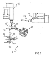
- a robotized work station intended to assemble the tread band 6 of the pneumatic tire 1 illustrated in figure 3A is generally indicated at 16.
- the work station 16 is associated to a conventional building plant for the production of pneumatic tires, or for carrying out part of the working operations foreseen in the production cycle of the pneumatic tires themselves, plant that is otherwise not illustrated being known per se.
- apparatuses known per se and not illustrated are also present for assembling the carcass structure 2 and the annular reinforcing structure 3 associated thereto on a supporting element capable to assume a substantially toroidal configuration, such as for example a building drum 18 known per se , as well as for subsequently assembling the belt structure 5 at a radially outer position with respect to the carcass structure 2.
- the work station 16 comprises a robotized arm known per se, generally indicated at 21 and preferably of the anthropomorphic type with seven axes, intended to pick up each drum 18 supporting the carcass structure 2, the annular reinforcing structure 3 and the belt structure 5 from a pick up position 20, defined at the end of a conveyor belt 19 or other suitable transporting means, to a delivery position of the sectors 9, 10 of the tread band 6.
- the delivery position of the first sectors 9 of the tread band 6 is defined at a first delivery member 22 of an extruder 23, adapted to provide at least one first continuous elongated element consisting of an elongated element 24 made of a suitable elastomeric material having a suitable size in cross-section
- the delivery position of the second sectors 10 of the tread band 6 is defined at a second delivery member 25 of an extruder 26, adapted to provide at least one second continuous elongated element consisting of an elongated element 27 also consisting of a suitable elastomeric material having a suitable size in cross section.
- the carcass structure 2 comprising the annular reinforcing structure 3 and the belt structure 5 are assembled and shaped on the drum 18 which assumes and then determines a substantially toroidal shape of the pneumatic tire under construction. Said drum 18 is then transported by the conveyor belt 19 to the pick up position 20.
- the robotized arm 21 positions the drum 18 in the first delivery position defined at the first delivery member 22 of the elongated element 24 consisting of the first elastomeric material having after vulcanization a modulus of elasticity E' under compression at 23°C comprised between about 20 and about 80 MPa and intended to form the first sectors 9 of the tread band 6.
- the robotized arm 21 rotates the drum 18 about its rotation axis X-X and carries out a relative displacement between the delivery member 22 and the drum 18 by also imparting to the latter a translational movement along a direction substantially parallel to the aforementioned rotation axis X-X.
- the first delivery member 22 delivers the elongated element 24 at a radially outer position with respect to the belt layer 5 so as to form the first sectors 9 of the tread band 6 in which the longitudinal grooves shall subsequently be formed.
- the rotation and translation movement of the drum 18 is suitably driven in such a way as to form a plurality of first sectors 9 axially spaced apart by the predetermined pitch p.
- the delivery of the elongated element 24 is carried out by forming a plurality of coils axially arranged side-by-side and/or radially superposed so as to define the first sectors 9.
- the robotized arm 21 positions the drum 18 in the second delivery position defined at the second delivery member 25 of the elongated element 27 made of the second elastomeric material intended to form the second sectors 10 of the tread band 6 and having after vulcanization a value of the modulus of elasticity E' under compression at 23°C lower than that of the first elastomeric material constituting the first sectors 9.
- the robotized arm 21 rotates the auxiliary drum 18 about its rotation axis X-X and carries out a relative displacement between the delivery member 25 and the auxiliary drum 18 also imparting to the latter a translational movement along a direction substantially parallel to the aforementioned rotation axis X-X.
- the second delivery member 25 delivers the elongated element 27 at a radially outer position with respect to the belt layer 5 so as to form the second sectors 10 of the tread band 6 between the first sectors 9 previously formed.
- the rotation and translation movement of the drum 18 is suitably driven so as to form a plurality of second sectors 10 axially spaced apart by the predetermined pitch p.
- the delivery of the elongated element 27 is preferably carried out by forming a plurality of coils axially arranged side-by-side and/or radially superposed.
- the tread band 6 of the green pneumatic tire being built may be deemed to be complete for which reason the drum 18 is transported in a way known per se and not shown to the subsequent work stations of the plant.
- a forming step of the longitudinal grooves 11 in the first sectors 9 and a vulcanization step of the pneumatic tire are then carried out in a way known per se in a work station, also conventional per se and not shown.
- the deposition sequence of the sectors 9, 10 is not critical, for which reason it is also possible to foresee that the second sectors 10 are formed before the first sectors 9 at a radially outer position with respect to the belt layer 5.
- a substantially cylindrical auxiliary drum 18' is used on which the belt structure 5 is assembled.
- the auxiliary drum 18' is substantially moved like the drum 18 previously illustrated.
- the auxiliary drum 18' is placed at the first delivery member 22 of the first elastomeric material; then, an elongated element 24 of said first elastomeric material is delivered by means of the delivery member 22 on the belt structure 5, preferably while carrying out a relative displacement between the first delivery member 22 and the auxiliary drum 18' so as to form the first sectors 9 of the tread band 6.
- the auxiliary drum 18' is positioned at the second delivery member 25 of the second elastomeric material, and an elongated element 27 delivered by the member 25 is deposited on the belt structure 5, preferably while carrying out a relative displacement between the second delivery member 25 and the auxiliary drum 18' so as to form the second sectors 10 of the tread band 6 between the first sectors 9 previously formed.
- the steps of delivering the aforementioned elongated elements of elastomeric material are preferably carried out by rotating the auxiliary drum 18' about its rotation axis.
- the aforementioned delivering steps are carried out by forming a plurality of coils axially arranged side-by-side and/or radially superposed so as to define the first and second sectors 9, 10 of the tread band 6.
- the relative displacement between the delivery members 22 and 25 and the auxiliary drum 18' is carried out by imparting to the auxiliary drum 18' a translational movement along a direction substantially parallel to its rotation axis.
- the deposition sequence of the sectors 9, 10 is not critical, for which reason it is possible to foresee that the second sectors 10 are formed before the first sectors 9 at a radially outer position with respect to the belt layer 5.
- the belt structure-tread band assembly is associated to the remaining parts of the pneumatic tire being built waiting on a different building drum.
- a work station intended to manufacture the tread band 6 of the pneumatic tire 1 is generally indicated at 17.
- the work station 17 is in particular associated to a highly automated plant for building pneumatic tires, or for carrying out part of the working operations foreseen in the production cycle of the pneumatic tires themselves, a plant otherwise not illustrated being known per se.
- robotized stations not illustrated herein are also present for building on the toroidal support 28 the carcass structure 2 comprising the annular reinforcing structure 3 and for the subsequent assembly of the belt structure 5 at a radially outer position with respect to the carcass structure 2.
- the work station 17 comprises a robotized arm known per se, generally indicated at 29 and preferably of the anthropomorphic type with seven axes, intended to pick up each support 28 carrying the carcass structure 2, the annular reinforcing structure 3 and the belt structure 5 from a pick up position 30, defined at the end of two supporting arms 36, 37 of a trestle 31 or other suitable supporting means, to a delivery position of the sectors 9 and 10 of the tread band 6.
- the delivery position of the first sectors 9 of the tread band 6 is defined at a first delivery member 32 of an extruder 33, adapted to provide at least one first continuous elongated element consisting of an elongated element (not visible in figure 6 ) made of a suitable first elastomeric material having a suitable size in cross section
- the delivery position of the second sectors 10 of the tread band 6 is defined at a second delivery member 34 of an extruder 35, adapted to provide at least a second continuous elongated element consisting of an elongated element (also not visible in figure 6 ) consisting of a suitable second elastomeric material having a suitable size in cross section.
- the carcass structure 2, the annular reinforcing structure 3 and the belt structure 5 are built on the support 28 which is then transported to the pick up position 30.
- the robotized arm 29 positions the support 28 in the first delivery position defined at the first delivery member 32 of the elongated member consisting of the first elastomeric material having after vulcanization a value of the modulus of elasticity E' under compression at 23°C comprised between about 20 and about 80 MPa and intended to form the first sectors 9 of the tread band 6.
- the robotized arm 29 rotates the support 28 about its rotation axis X-X and carries out a relative displacement between the delivery member 32 and the support 28 also imparting to the latter a translational movement along a direction substantially parallel to the aforementioned rotation axis X-X.
- the first delivery member 32 delivers the elongated element at a radially outer position with respect to the belt layer 5 so as to form the first sectors 9 of the tread band 6.
- the delivery of the elongated element is carried out by forming a plurality of coils axially arranged side-by-side and/or radially superposed so as to define the first sectors 9.
- the robotized arm 29 positions the support 28 in the second delivery position defined at the second delivery member 34 of the elongated element consisting of the second elastomeric material having after vulcanization a value of the modulus of elasticity E' under compression at 23°C lower than that of the first elastomeric material constituting the first sectors 9.
- the robotized arm 29 rotates the support 28 about its rotation axis X-X and carries out a relative displacement between the delivery member 34 and the support 28 also imparting to the latter a translational movement along a direction substantially parallel to the aforementioned rotation axis X-X.
- the second delivery member 34 delivers the elongated element at a radially outer position with respect to the belt layer 5 so as to form the second sectors 10 of the tread band 6 between the first sectors 9 previously formed.
- the delivery of the elongated element is preferably carried out by forming a plurality of coils axially arranged side-by-side and/or radially superposed.
- the deposition sequence of the first and second sectors 9, 10 is not critical, for which reason it is possible to foresee that the second sectors 10 are formed before the first sectors 9 at a radially outer position with respect to the belt layer 5.
- the tread band 6 of the green pneumatic tire being built may be deemed to be complete for which reason the support 28 is transported, in a way known per se and not shown, to the subsequent work stations of the plant.
- the green pneumatic tire thus obtained is sent to the step of forming the longitudinal grooves 11 and of vulcanization.
- This different preferred embodiment of the process according to the invention has in particular an advantageous and effective application when it is desired to use production techniques which allow to minimize or, possibly, eliminate the production and storage of the semifinished products, for example by adopting process solutions which allow to make the individual components by directly applying them on the pneumatic tire being manufactured according to a predetermined sequence by means of a plurality of robotized stations.
- the building process also comprises the step of the depositing the aforementioned layer at a radially outer position with respect to the belt structure 5 before the depositing the first or second sectors 9, 10 of the tread band.
- This additional delivery step shall advantageously be carried out at the first or second delivery position according to the type of material to be used to form the layer 12.
Landscapes
- Engineering & Computer Science (AREA)
- Mechanical Engineering (AREA)
- Tires In General (AREA)
- Tyre Moulding (AREA)
Claims (34)
- Luftreifen (1)- mit einem Karkassenaufbau (2), der wenigstens eine Karkassenlage (2a) und wenigstens einen ihr zugeordneten ringförmigen Verstärkungsaufbau (3) aufweist,- mit einem Laufflächenband (6) aus einem elastomeren Material an einer radial äußeren Position bezogen auf den Karkassenaufbau (2),- mit einem Gurtaufbau (5), der zwischen dem Karkassenaufbau und dem Laufflächenband (6) angeordnet ist, und- mit einem Paar von axial gegenüberliegenden Seitenwänden (7, 8) an dem Karkassenaufbau (2),- wobei das Laufflächenband (6)i) wenigstens einen ersten Abschnitt (9), der sich radial erstreckt und im Wesentlichen aus einem ersten elastomeren Material besteht,ii) eine Vielzahl von zweiten Abschnitten (10), die sich radial erstrecken, auf axial gegenüberliegenden Seiten des wenigstens einen ersten Abschnitts (9) angeordnet sind und im Wesentlichen aus einem zweiten elastomeren Material bestehen, undiii) wenigstens eine Längsnut (11) aufweist, die in dem wenigstens einen ersten Abschnitt (9) ausgebildet ist und sich im Wesentlichen über die ganze Umfangsabwicklung des Laufflächenbandes (6) erstreckt,- wobei das erste elastomere Material einen Elastizitätsmodul (E') unter Kompression bei 23°C hat, der größer ist als der Elastizitätsmodul (E') unter Kompression bei 23°C des zweiten elastomeren Materials, und- wobei der Elastizitätsmodul (E') unter Kompression bei 23°C des ersten elastomeren Materials zwischen etwa 20 und etwa 80 MPa liegt.
- Luftreifen (1) nach Anspruch 1, bei welchem der Elastizitätsmodul (E') unter Kompression bei 23°C des zweiten elastomeren Materials zwischen etwa 4 und etwa 15 MPa liegt.
- Luftreifen (1) nach Anspruch 1 oder 2, bei welchem das Verhältnis zwischen dem Elastizitätsmodul (E') unter Kompression bei 23°C des ersten elastomeren Materials und dem Elastizitätsmodul (E') unter Kompression bei 23°C des zweiten elastomeren Materials des Laufflächenbandes nicht weniger als etwa 1,30 beträgt.
- Luftreifen (1) nach Anspruch 3, bei welchem das Verhältnis zwischen dem Elastizitätsmodul (E') unter Kompression bei 23°C des ersten elastomeren Materials und dem Elastizitätsmodul (E') unter Kompression bei 23°C des zweiten elastomeren Materials zwischen etwa 1,5 und etwa 20 liegt.
- Luftreifen (1) nach Anspruch 4, bei welchem das Verhältnis zwischen dem Elastizitätsmodul (E') unter Kompression bei 23°C des ersten elastomeren Materials und dem Elastizitätsmodul (E') unter Kompression bei 23°C des zweiten elastomeren Materials zwischen etwa 2,3 und etwa 7 liegt.
- Luftreifen (1) nach Anspruch 1, bei welchem die IRHD-Härte bei 23°C des ersten elastomeren Materials, gemessen nach der Norm ISO 48, zwischen etwa 75 und etwa 95 liegt.
- Luftreifen (1) nach Anspruch 1, bei welchem die IRHD-Härte bei 23°C des zweiten elastomeren Materials, gemessen nach der Norm ISO 48, zwischen etwa 35 und etwa 80 liegt.
- Luftreifen (1) nach Anspruch 6 und 7, bei welchem das Verhältnis zwischen der IRHD-Härte bei 23°C des ersten elastomeren Materials, gemessen nach der Norm ISO 48, und der IRHD-Härte bei 23°C des zweiten elastomeren Materials, gemessen nach der Norm ISO 48, nicht weniger als 1,10 beträgt.
- Luftreifen (1) nach Anspruch 8, bei welchem das Verhältnis zwischen der IRHD-Härte bei 23°C des ersten elastomeren Materials, gemessen nach der Norm ISO 48, und der IRHD-Härte bei 23°C des zweiten elastomeren Materials, gemessen nach der Norm ISO 48, zwischen etwa 1,15 und etwa 2,70 liegt.
- Luftreifen (1) nach Anspruch 1, bei welchem das Laufflächenband (6) mit einer Vielzahl von Längsnuten (11) versehen ist und die Nuten (11) in entsprechenden ersten Abschnitten (9) ausgebildet sind, die sich radial erstrecken, axial beabstandet sind und im Wesentlichen aus dem ersten elastomeren Material bestehen.
- Luftreifen (1) nach Anspruch 1 oder 10, bei welchem der wenigstens eine erste Abschnitt (9) sich radial im Wesentlichen über der gesamten Dicke des Laufflächenbandes (6) erstreckt.
- Luftreifen (1) nach Anspruch 1 oder 10, bei welchem eine zusätzliche Schicht (12) aus elastomerem Material zwischen dem Laufflächenband (6) und dem Gurtaufbau (5) angeordnet ist.
- Luftreifen (1) nach Anspruch 12, bei welchem die Schicht (12) im Wesentlichen aus dem ersten elastomeren Material besteht.
- Luftreifen (1) nach Anspruch 12, bei welchem die Schicht (12) im Wesentlichen aus dem zweiten elastomeren Material besteht.
- Luftreifen (1) nach Anspruch 12, bei welchem die Schicht (12) eine Dicke zwischen 1 und 5 mm hat.
- Luftreifen (1) nach Anspruch 1 oder 10, bei welchem die Breite des wenigstens einen ersten Abschnitts (9) wenigstens gleich der Breite der wenigstens einen Längsnut (11) ist.
- Luftreifen (1) nach Anspruch 16, bei welchem die Differenz zwischen der Breite des wenigstens einen ersten Abschnitts (9) und der Breite der wenigstens einen Längsnut (11) zwischen 4 und 10 mm beträgt.
- Luftreifen (1) nach Anspruch 1 oder 10, bei welchem die wenigstens eine Längsnut (11) rittlings zur Mittelebene (m) des wenigstens einen ersten Abschnitts (9) angeordnet ist.
- Verfahren zum Herstellen eines Luftreifens (1), welches die Schritte aufweist:a) Aufbauen eines Karkassenaufbaus (2), der wenigstens eine Karkassenlage (2a) hat, die wenigstens einem ringförmigen Verstärkungsaufbau (3) zugeordnet ist,b) Hinzufügen eines Gurtaufbaus (5),c) Anordnen an einer radial äußeren Position bezüglich des Gurtaufbaus (5) wenigstens eines sich radial erstreckenden ersten Abschnitts (9) des Laufflächenbandes (6), der im Wesentlichen aus einem ersten elastomeren Material besteht, das nach dem Vulkanisieren einen Wert des Elastizitätsmoduls (E') unter Kompression bei 23°C zwischen etwa 20 und etwa 80 MPa hat, undd) Anordnen an einer radial äußeren Position bezüglich des Gurtaufbaus (5) einer Vielzahl von sich radial erstreckenden zweiten Abschnitten (10) des Laufflächenbandes (6), die axial beabstandet sind und im Wesentlichen aus einem zweiten elastomeren Material bestehen, das nach dem Vulkanisieren einen Wert des Elastizitätsmoduls (E') unter Kompression bei 23°C hat, der niedriger ist als der Wert des Elastizitätsmoduls (E') unter Kompression bei 23°C des ersten elastomeren Materials,- wobei die Schritte c) und d) so ausgeführt werden, dass die zweiten Abschnitte (10) an axial gegenüberliegenden Seiten des wenigstens einen ersten Abschnitts (9) angeordnet sind.
- Verfahren nach Anspruch 19, bei welchem der Gurtaufbau (5) auf einer im Wesentlichen zylindrischen Zusatztrommel (18') geformt wird und die Schritte c) und d) die Schritte aufweisen:e) Positionieren der Zusatztrommel (18') an einem ersten Lieferelement (22) für das erste elastomere Material,f) Liefern mit Hilfe des ersten Lieferelements (22) wenigstens eines langgestreckten Elements (24) aus dem ersten elastomeren Material an einer radial äußeren Position bezüglich des Gurtaufbaus (5), während eine Relativverschiebung zwischen dem ersten Lieferelement (22) und der Zusatztrommel (18') so ausgeführt wird, dass der wenigstens eine erste Abschnitt (9) des Laufflächenbandes (6) gebildet wird,g) Positionieren der Zusatztrommel (18') an einem zweiten Lieferelement (25) für das zweite elastomere Material undh) Liefern mit Hilfe des zweiten Lieferelements (25) wenigstens eines langgestreckten Elements (27) aus dem zweiten elastomeren Material an einer radial äußeren Position bezogen auf den Gurtaufbaus (5), während eine Relativverschiebung zwischen dem zweiten Lieferelement (25) und der Zusatztrommel (18') so ausgeführt wird, dass die zweiten Abschnitte (10) des Laufflächenbandes (6) axial beabstandet und auf gegenüberliegenden Seiten des wenigstens einen ersten Abschnitts (9) angeordnet gebildet werden.
- Verfahren nach Anspruch 20, bei welchem die Schritte f) und h) des Liefems der langgestreckten Elemente (24, 27) des ersten und zweiten elastomeren Materials dadurch ausgeführt werden, dass die Zusatztrommel (18') um ihre Drehachse (X-X) gedreht wird.
- Verfahren nach Anspruch 20 oder 21, bei welchem die Relativverschiebung zwischen dem Lieferelement (22, 25) und der Zusatztrommel (18') dadurch ausgeführt wird, dass der Zusatztrommel (18') eine erste Translationsbewegung längs einer Richtung im Wesentlichen parallel zu ihrer Drehachse (X-X) und/oder eine zweite Translationsbewegung längs einer Richtung im Wesentlichen senkrecht zu der Achse (X-X) erteilt wird.
- Verfahren nach Anspruch 20, bei welchem die Schritte f) und h) des Liefems der langgestreckten Elemente des ersten und zweiten elastomeren Materials dadurch ausgeführt werden, dass zur Bildung des wenigstens einen ersten Abschnitts (9) und der zweiten Abschnitte (10) des Laufflächenbandes (6) eine Vielzahl von axial nebeneinander und/oder radial aufeinander angeordneten Windungen gebildet wird.
- Verfahren nach Anspruch 19, bei welchem der Gurtaufbau (5) auf einem im Wesentlichen torusförmigen Träger (18, 28) montiert wird und die Schritte c) und d) die Schritte aufweisen:e') Positionieren des im Wesentlichen torusförmigen Trägers (18, 28) an einem ersten Lieferelement (22, 32) für das erste elastomere Material,f) Liefern mit Hilfe des ersten Lieferelements (22, 32) wenigstens eines langgestreckten Elements aus dem ersten elastomeren Material an einer radial äußeren Position bezogen auf den Gurtaufbau (5), während eine Relativverschiebung zwischen dem ersten Lieferelement (22, 32) und dem im Wesentlichen torusförmigen Träger (18, 28) so ausgeführt wird, dass wenigstens ein erster Abschnitt (9) des Laufflächenbandes (6) gebildet wird,g') Positionieren des im Wesentlichen torusförmigen Trägers (18, 28) an einem zweiten Lieferelement (25, 34) für das zweite elastomere Material undh') Liefern mit Hilfe des zweiten Lieferelements (25, 34) wenigstens eines langgestreckten Elements aus dem zweiten elastomeren Material an einer radial äußeren Position bezogen auf den Gurtaufbau (5), während eine Relativverschiebung zwischen dem zweiten Lieferelement (25, 34) und dem im Wesentlichen torusförmigen Träger (18, 28) so ausgeführt wird, dass die zweiten Abschnitte (10) des Laufflächenbandes (6) axial beabstandet und auf axial gegenüberliegenden Seiten des wenigstens einen ersten Abschnitts (9) gebildet werden.
- Verfahren nach Anspruch 24, bei welchem die Schritte f) und h') des Lieferns der langgestreckten Elemente aus dem ersten und zweiten elastomeren Material dadurch ausgeführt werden, dass der im Wesentlichen torusförmige Träger (18, 28) um seine Drehachse (X-X) gedreht wird.
- Verfahren nach Anspruch 24 oder 25, bei welchem die Relativverschiebung zwischen dem Lieferelement (32, 34) und dem im Wesentlichen torusförmigen Träger (18, 28) dadurch ausgeführt wird, dass dem im Wesentlichen torusförmigen Träger (18, 28) eine erste Translationsbewegung längs einer Richtung im Wesentlichen parallel zu seiner Drehachse (X-X) und/oder eine zweite Translationsbewegung längs einer Richtung im Wesentlichen senkrecht zu der Achse (X-X) erteilt wird.
- Verfahren nach Anspruch 24, bei welchem die Schritte f) und h') des Liefems der langgestreckten Elemente aus dem ersten und zweiten elastomeren Material dadurch ausgeführt werden, dass eine Vielzahl von Windungen axial nebeneinander und/oder radial aufeinander angeordnet gebildet werden, um den wenigstens einen ersten Abschnitt (9) und die zweiten Abschnitte (10) des Laufflächenbandes (6) zu bilden.
- Verfahren nach Anspruch 24, bei welchem der im Wesentlichen torusförmige Träger (28) im Wesentlichen starr ist.
- Verfahren nach einem der Ansprüche 19 bis 28, welches weiterhin den Schritt aufweist, an einer radial äußeren Position bezogen auf den Gurtaufbau (5) wenigstens eine zusätzliche Schicht (24) aus elastomerem Material zu liefern, bevor der Schritt c) des Lieferns des wenigstens einen ersten Abschnitts (9) ausgeführt wird.
- Verfahren nach einem der Ansprüche 19 bis 28, welches weiterhin den Schritt aufweist, an einer radial äußeren Position bezogen auf den Gurtaufbau (5) wenigstens eine zusätzliche Schicht (12) aus elastomerem Material gleichzeitig zum Schritt c) des Lieferns des wenigstens einen ersten Abschnitts (9) zu liefern.
- Verfahren nach einem der Ansprüche 19 bis 28, welches weiterhin den Schritt aufweist, an einer radial äußeren Position bezogen auf den Gurtaufbau (5) wenigstens eine zusätzliche Schicht (12) aus elastomerem Material zu liefern, bevor der Schritt d) des Lieferns der Vielzahl von zweiten Abschnitten (10) ausgeführt wird.
- Verfahren nach einem der Ansprüche 19 bis 28, welches weiterhin den Schritt aufweist, an einer radial äußeren Position bezogen auf den Gurtaufbau (5) wenigstens eine zusätzliche Schicht (12) aus elastomerem Material gleichzeitig zu dem Schritt d) des Lieferns der Vielzahl von zweiten Abschnitten (10) zu liefern.
- Verfahren nach einem der Ansprüche 29 bis 32, bei welchem die Schicht (12) im Wesentlichen aus dem ersten elastomeren Material besteht.
- Verfahren nach einem der Ansprüche 29 bis 32, bei welchem die Schicht (12) im Wesentlichen aus dem zweiten elastomeren Material besteht.
Applications Claiming Priority (1)
| Application Number | Priority Date | Filing Date | Title |
|---|---|---|---|
| PCT/IT2003/000867 WO2005063509A1 (en) | 2003-12-30 | 2003-12-30 | Pneumatic tire and process for its manufacture |
Publications (2)
| Publication Number | Publication Date |
|---|---|
| EP1708896A1 EP1708896A1 (de) | 2006-10-11 |
| EP1708896B1 true EP1708896B1 (de) | 2008-03-26 |
Family
ID=34717605
Family Applications (1)
| Application Number | Title | Priority Date | Filing Date |
|---|---|---|---|
| EP03819232A Expired - Lifetime EP1708896B1 (de) | 2003-12-30 | 2003-12-30 | Luftreifen und verfahren für seine herstellung |
Country Status (13)
| Country | Link |
|---|---|
| US (1) | US8104523B2 (de) |
| EP (1) | EP1708896B1 (de) |
| JP (1) | JP4621141B2 (de) |
| KR (1) | KR101064612B1 (de) |
| CN (1) | CN100537275C (de) |
| AR (1) | AR047172A1 (de) |
| AT (1) | ATE390300T1 (de) |
| AU (1) | AU2003300755A1 (de) |
| BR (1) | BR0318675B1 (de) |
| CA (1) | CA2552154A1 (de) |
| DE (1) | DE60320048T2 (de) |
| ES (1) | ES2304556T3 (de) |
| WO (1) | WO2005063509A1 (de) |
Cited By (4)
| Publication number | Priority date | Publication date | Assignee | Title |
|---|---|---|---|---|
| US9623707B2 (en) | 2014-12-10 | 2017-04-18 | The Goodyear Tire & Rubber Company | Tire with groove reinforcement |
| US10427463B2 (en) | 2016-11-16 | 2019-10-01 | The Goodyear Tire & Rubber Company | Pneumatic tire having a dual layer tread |
| US10967679B2 (en) | 2015-10-20 | 2021-04-06 | Compagnie Generale Des Etablissements Michelin | Tire with a tread having reinforced sectors and self-maintaining recesses |
| FR3115498A1 (fr) | 2020-10-28 | 2022-04-29 | Compagnie Generale Des Etablissements Michelin | Pneumatique avec une bande de roulement comportant des rainures circonférentielles renforcées |
Families Citing this family (27)
| Publication number | Priority date | Publication date | Assignee | Title |
|---|---|---|---|---|
| EP1609624A1 (de) * | 2004-06-24 | 2005-12-28 | Continental Aktiengesellschaft | Fahrzeugluftreifen |
| JP5152450B2 (ja) * | 2006-07-24 | 2013-02-27 | 横浜ゴム株式会社 | 空気入りタイヤ |
| US20080216930A1 (en) * | 2007-03-05 | 2008-09-11 | Christopher John Valentine | Tyre with rubber tread which contains internal circumferential rubber stabilizer bars |
| JP2009255856A (ja) * | 2008-04-21 | 2009-11-05 | Bridgestone Corp | 空気入りタイヤ |
| JP5237901B2 (ja) * | 2009-08-24 | 2013-07-17 | 東洋ゴム工業株式会社 | 空気入りタイヤ |
| FR2954223B1 (fr) * | 2009-12-22 | 2016-01-01 | Michelin Soc Tech | Pneumatique ayant une bande de roulement perfectionnee |
| US9878508B2 (en) | 2010-11-30 | 2018-01-30 | The Goodyear Tire & Rubber Company | Stiffness enhanced tread element |
| US8413697B2 (en) * | 2011-08-31 | 2013-04-09 | The Goodyear Tire & Rubber Company | Pneumatic tire having a dual layer tread |
| US9283817B2 (en) * | 2011-11-22 | 2016-03-15 | The Goodyear Tire & Rubber Company | Stiffness enhanced tread |
| US20130126060A1 (en) * | 2011-11-22 | 2013-05-23 | Kenneth Lee Oblizajek | Stiffness enhanced tread |
| CN103998256B (zh) * | 2011-12-16 | 2016-08-24 | 米其林企业总公司 | 用于充气轮胎的胎面 |
| FR2984227B1 (fr) | 2011-12-16 | 2015-04-03 | Michelin Soc Tech | Bande de roulement ayant des elements de sculpture recouverts d'un materiau thermoplastique. |
| JP6065432B2 (ja) * | 2012-07-12 | 2017-01-25 | 横浜ゴム株式会社 | プレキュア更生タイヤ |
| KR101325396B1 (ko) * | 2012-08-21 | 2013-11-08 | 한국타이어 주식회사 | 차량용 타이어의 트레드 및 그를 포함하는 차량용 타이어 |
| US9027615B2 (en) * | 2012-09-12 | 2015-05-12 | The Goodyear Tire & Rubber Company | Tire tread with groove reinforcement |
| WO2014192962A1 (ja) * | 2013-05-31 | 2014-12-04 | 株式会社ブリヂストン | タイヤ及びタイヤの製造方法 |
| US9757986B2 (en) * | 2013-12-19 | 2017-09-12 | The Goodyear Tire & Rubber Company | Tire having tread with tread groove-containing rubber block joining the tire carcass and extending through a tread base into a tread cap |
| EP3288782B1 (de) * | 2015-04-28 | 2019-08-07 | Compagnie Générale des Etablissements Michelin | Reifen mit einer lauffläche mit verstärkungselementen |
| EP3208110B1 (de) * | 2016-02-17 | 2018-08-15 | Nexen Tire Corporation | Reifenlauffläche und luftreifen |
| US11518194B2 (en) | 2016-06-30 | 2022-12-06 | Compagnie Generale Des Etablissements Michelin | Tire comprising a tread containing reinforcing elements |
| JP6807722B2 (ja) * | 2016-11-29 | 2021-01-06 | Toyo Tire株式会社 | 空気入りタイヤ |
| FR3059601A3 (fr) * | 2016-12-02 | 2018-06-08 | Michelin & Cie | Pneumatique avec une bande de roulement comportant des elements de renforcement circonferentiels dans la sous-couche |
| FR3059943A1 (fr) | 2016-12-13 | 2018-06-15 | Compagnie Generale Des Etablissements Michelin | Pneumatique avec une bande de roulement comportant des elements de renforcement |
| FR3063934A1 (fr) * | 2017-03-20 | 2018-09-21 | Compagnie Generale Des Etablissements Michelin | Pneumatique dont la bande de roulement comporte des rainures avec faces laterales en contre-depouille et des elements de renforcement |
| WO2019002782A1 (fr) * | 2017-06-30 | 2019-01-03 | Compagnie Generale Des Etablissements Michelin | Tete d'extrusion avec chenaux pour la réalisation d'inserts dans une bande profilée destinée à la fabrication d'un pneumatique et procédé d'extrusion correspondant |
| JP6949649B2 (ja) * | 2017-10-02 | 2021-10-13 | 株式会社ブリヂストン | タイヤ |
| DE102023211877A1 (de) * | 2023-11-28 | 2025-05-28 | Continental Reifen Deutschland Gmbh | Luftreifen und Verfahren zur Herstellung desselben |
Family Cites Families (21)
| Publication number | Priority date | Publication date | Assignee | Title |
|---|---|---|---|---|
| FR2128041B1 (de) * | 1971-03-01 | 1974-09-06 | Kleber Colombes | |
| JPS5380602A (en) | 1976-12-27 | 1978-07-17 | Bridgestone Corp | Pneumatic tire with superior irregular wear resistance |
| JPH02249707A (ja) | 1989-03-22 | 1990-10-05 | Bridgestone Corp | 空気入りタイヤ |
| JPH04185507A (ja) | 1990-11-21 | 1992-07-02 | Yokohama Rubber Co Ltd:The | 空気入りラジアルタイヤ |
| JP3359958B2 (ja) | 1993-10-14 | 2002-12-24 | 株式会社ブリヂストン | スパイラルベルト構造の二輪車用空気入りタイヤ |
| GB9409453D0 (en) * | 1994-05-12 | 1994-06-29 | Sumitomo Rubber Ind | tyre tread and tyres incorporating them |
| EP0847880B1 (de) * | 1996-10-17 | 2002-12-18 | Sumitomo Rubber Industries Limited | Luftreifen |
| DE19643998C2 (de) | 1996-10-31 | 1999-03-25 | Continental Ag | Fahrzeugluftreifen |
| US6523585B1 (en) | 1997-03-18 | 2003-02-25 | Bridgestone Corporation | Antistatic tire |
| JP4315526B2 (ja) * | 1998-07-08 | 2009-08-19 | 株式会社ブリヂストン | 帯状未加硫ゴムの積層方法 |
| JP4392068B2 (ja) * | 1998-10-14 | 2009-12-24 | 住友ゴム工業株式会社 | 空気入りタイヤ |
| BR9916360B1 (pt) | 1998-12-17 | 2008-11-18 | processo para fabricaÇço de componentes de um pneu para rodas de veÍculo. | |
| KR100675773B1 (ko) * | 1998-12-17 | 2007-02-01 | 피렐리 타이어 소시에떼 퍼 아찌오니 | 차륜용 타이어 부품 제작 방법 및 장치 |
| TW482732B (en) * | 1998-12-21 | 2002-04-11 | Pirelli | Dual composition tread band for tire |
| WO2001003954A1 (en) | 1999-07-09 | 2001-01-18 | Pirelli Pneumatici Spa | High performance tyre with tread band having an anisotropic underlayer stable upon temperature variation |
| PT1095795E (pt) * | 1999-10-28 | 2006-12-29 | Pirelli | Pneu de baixa resistência do rolamento para veículos |
| JP2001206013A (ja) | 2000-01-26 | 2001-07-31 | Bridgestone Corp | 空気入りタイヤ |
| JP5013636B2 (ja) * | 2000-05-24 | 2012-08-29 | 株式会社ブリヂストン | タイヤ構成部材の成形方法 |
| JP2002052906A (ja) * | 2000-08-11 | 2002-02-19 | Bridgestone Corp | 空気入りタイヤ |
| JP2002307911A (ja) * | 2001-04-13 | 2002-10-23 | Yokohama Rubber Co Ltd:The | 重荷重用空気入りタイヤおよびその製造方法 |
| JP4262436B2 (ja) * | 2002-05-01 | 2009-05-13 | 住友ゴム工業株式会社 | 空気入りタイヤ |
-
2003
- 2003-12-30 ES ES03819232T patent/ES2304556T3/es not_active Expired - Lifetime
- 2003-12-30 KR KR1020067013091A patent/KR101064612B1/ko not_active Expired - Fee Related
- 2003-12-30 WO PCT/IT2003/000867 patent/WO2005063509A1/en not_active Ceased
- 2003-12-30 AU AU2003300755A patent/AU2003300755A1/en not_active Abandoned
- 2003-12-30 CN CNB2003801109247A patent/CN100537275C/zh not_active Expired - Fee Related
- 2003-12-30 DE DE60320048T patent/DE60320048T2/de not_active Expired - Lifetime
- 2003-12-30 US US10/584,798 patent/US8104523B2/en not_active Expired - Fee Related
- 2003-12-30 BR BRPI0318675-0A patent/BR0318675B1/pt not_active IP Right Cessation
- 2003-12-30 CA CA002552154A patent/CA2552154A1/en not_active Abandoned
- 2003-12-30 EP EP03819232A patent/EP1708896B1/de not_active Expired - Lifetime
- 2003-12-30 JP JP2005512779A patent/JP4621141B2/ja not_active Expired - Fee Related
- 2003-12-30 AT AT03819232T patent/ATE390300T1/de not_active IP Right Cessation
-
2004
- 2004-12-28 AR ARP040104925A patent/AR047172A1/es unknown
Cited By (5)
| Publication number | Priority date | Publication date | Assignee | Title |
|---|---|---|---|---|
| US9623707B2 (en) | 2014-12-10 | 2017-04-18 | The Goodyear Tire & Rubber Company | Tire with groove reinforcement |
| US10967679B2 (en) | 2015-10-20 | 2021-04-06 | Compagnie Generale Des Etablissements Michelin | Tire with a tread having reinforced sectors and self-maintaining recesses |
| US10427463B2 (en) | 2016-11-16 | 2019-10-01 | The Goodyear Tire & Rubber Company | Pneumatic tire having a dual layer tread |
| FR3115498A1 (fr) | 2020-10-28 | 2022-04-29 | Compagnie Generale Des Etablissements Michelin | Pneumatique avec une bande de roulement comportant des rainures circonférentielles renforcées |
| WO2022090652A1 (fr) | 2020-10-28 | 2022-05-05 | Compagnie Generale Des Etablissements Michelin | Pneumatique avec une bande de roulement comportant des rainures circonférentielles renforcées |
Also Published As
| Publication number | Publication date |
|---|---|
| KR20060121257A (ko) | 2006-11-28 |
| US8104523B2 (en) | 2012-01-31 |
| ES2304556T3 (es) | 2008-10-16 |
| DE60320048T2 (de) | 2009-04-23 |
| US20070187013A1 (en) | 2007-08-16 |
| KR101064612B1 (ko) | 2011-09-15 |
| WO2005063509A1 (en) | 2005-07-14 |
| JP4621141B2 (ja) | 2011-01-26 |
| BR0318675B1 (pt) | 2014-01-14 |
| DE60320048D1 (de) | 2008-05-08 |
| AU2003300755A1 (en) | 2005-07-21 |
| EP1708896A1 (de) | 2006-10-11 |
| BR0318675A (pt) | 2006-11-28 |
| ATE390300T1 (de) | 2008-04-15 |
| CN100537275C (zh) | 2009-09-09 |
| JP2007528312A (ja) | 2007-10-11 |
| AR047172A1 (es) | 2006-01-11 |
| CN1886272A (zh) | 2006-12-27 |
| CA2552154A1 (en) | 2005-07-14 |
Similar Documents
| Publication | Publication Date | Title |
|---|---|---|
| US8104523B2 (en) | Pneumatic tire and process for its manufacture | |
| EP1667853B1 (de) | Luftreifen und verfahren für seine herstellung | |
| CN109414961B (zh) | 包括包含增强元件的胎面的轮胎 | |
| CN107531097B (zh) | 带有包括增强元件的胎面的轮胎 | |
| EP2708575B1 (de) | Kautschukzusammensetzung für Laufflächenrillenverstärkung | |
| EP1310385B1 (de) | Radialluftreifen | |
| EP2682286B1 (de) | Luftreifen | |
| CN100589998C (zh) | 用于车辆的轮胎 | |
| EP1618009B1 (de) | Luftreifen mit mehrschichtiger lauffläche und verfahren zur herstellung derselben | |
| EP1057659B1 (de) | Radialer Reifen für PKW | |
| JP3151035B2 (ja) | 空気入りラジアルタイヤ | |
| EP0778162B1 (de) | Luftreifen | |
| JP4912761B2 (ja) | 空気入りタイヤ | |
| RU2323099C1 (ru) | Пневматическая шина и способ ее изготовления | |
| RU2319618C2 (ru) | Пневматическая шина и способ ее изготовления | |
| JP5654868B2 (ja) | 空気入りタイヤ | |
| JP2012035823A (ja) | 空気入りタイヤユニット | |
| EP3932695A1 (de) | Motorradreifen | |
| JPH0253605A (ja) | ラジアルタイヤ | |
| RU2321500C1 (ru) | Шина для транспортных средств | |
| JPH0440179B2 (de) | ||
| CN121424870A (zh) | 高性能轮胎、轮胎模具和过程 | |
| JPS604402A (ja) | ハイモ−ルド法バイアス構造空気入りタイヤ | |
| BR132012021106E2 (pt) | Tire and process for manufacturing a tire | |
| TH83234A (th) | ยางรถยนต์ที่มีวัสดุเสริมแรงแก้มยาง |
Legal Events
| Date | Code | Title | Description |
|---|---|---|---|
| PUAI | Public reference made under article 153(3) epc to a published international application that has entered the european phase |
Free format text: ORIGINAL CODE: 0009012 |
|
| 17P | Request for examination filed |
Effective date: 20060721 |
|
| AK | Designated contracting states |
Kind code of ref document: A1 Designated state(s): AT BE BG CH CY CZ DE DK EE ES FI FR GB GR HU IE IT LI LU MC NL PT RO SE SI SK TR |
|
| DAX | Request for extension of the european patent (deleted) | ||
| GRAP | Despatch of communication of intention to grant a patent |
Free format text: ORIGINAL CODE: EPIDOSNIGR1 |
|
| GRAS | Grant fee paid |
Free format text: ORIGINAL CODE: EPIDOSNIGR3 |
|
| GRAA | (expected) grant |
Free format text: ORIGINAL CODE: 0009210 |
|
| AK | Designated contracting states |
Kind code of ref document: B1 Designated state(s): AT BE BG CH CY CZ DE DK EE ES FI FR GB GR HU IE IT LI LU MC NL PT RO SE SI SK TR |
|
| REG | Reference to a national code |
Ref country code: GB Ref legal event code: FG4D |
|
| REG | Reference to a national code |
Ref country code: IE Ref legal event code: FG4D Ref country code: CH Ref legal event code: EP |
|
| REF | Corresponds to: |
Ref document number: 60320048 Country of ref document: DE Date of ref document: 20080508 Kind code of ref document: P |
|
| REG | Reference to a national code |
Ref country code: RO Ref legal event code: EPE |
|
| REG | Reference to a national code |
Ref country code: SE Ref legal event code: TRGR |
|
| PG25 | Lapsed in a contracting state [announced via postgrant information from national office to epo] |
Ref country code: FI Free format text: LAPSE BECAUSE OF FAILURE TO SUBMIT A TRANSLATION OF THE DESCRIPTION OR TO PAY THE FEE WITHIN THE PRESCRIBED TIME-LIMIT Effective date: 20080326 |
|
| REG | Reference to a national code |
Ref country code: CH Ref legal event code: NV Representative=s name: FIAMMENGHI-FIAMMENGHI |
|
| NLV1 | Nl: lapsed or annulled due to failure to fulfill the requirements of art. 29p and 29m of the patents act | ||
| PG25 | Lapsed in a contracting state [announced via postgrant information from national office to epo] |
Ref country code: SI Free format text: LAPSE BECAUSE OF FAILURE TO SUBMIT A TRANSLATION OF THE DESCRIPTION OR TO PAY THE FEE WITHIN THE PRESCRIBED TIME-LIMIT Effective date: 20080326 |
|
| REG | Reference to a national code |
Ref country code: ES Ref legal event code: FG2A Ref document number: 2304556 Country of ref document: ES Kind code of ref document: T3 |
|
| PG25 | Lapsed in a contracting state [announced via postgrant information from national office to epo] |
Ref country code: SK Free format text: LAPSE BECAUSE OF FAILURE TO SUBMIT A TRANSLATION OF THE DESCRIPTION OR TO PAY THE FEE WITHIN THE PRESCRIBED TIME-LIMIT Effective date: 20080326 Ref country code: PT Free format text: LAPSE BECAUSE OF FAILURE TO SUBMIT A TRANSLATION OF THE DESCRIPTION OR TO PAY THE FEE WITHIN THE PRESCRIBED TIME-LIMIT Effective date: 20080901 Ref country code: CZ Free format text: LAPSE BECAUSE OF FAILURE TO SUBMIT A TRANSLATION OF THE DESCRIPTION OR TO PAY THE FEE WITHIN THE PRESCRIBED TIME-LIMIT Effective date: 20080326 |
|
| PG25 | Lapsed in a contracting state [announced via postgrant information from national office to epo] |
Ref country code: NL Free format text: LAPSE BECAUSE OF FAILURE TO SUBMIT A TRANSLATION OF THE DESCRIPTION OR TO PAY THE FEE WITHIN THE PRESCRIBED TIME-LIMIT Effective date: 20080326 |
|
| ET | Fr: translation filed | ||
| PG25 | Lapsed in a contracting state [announced via postgrant information from national office to epo] |
Ref country code: DK Free format text: LAPSE BECAUSE OF FAILURE TO SUBMIT A TRANSLATION OF THE DESCRIPTION OR TO PAY THE FEE WITHIN THE PRESCRIBED TIME-LIMIT Effective date: 20080326 |
|
| PLBE | No opposition filed within time limit |
Free format text: ORIGINAL CODE: 0009261 |
|
| STAA | Information on the status of an ep patent application or granted ep patent |
Free format text: STATUS: NO OPPOSITION FILED WITHIN TIME LIMIT |
|
| PGFP | Annual fee paid to national office [announced via postgrant information from national office to epo] |
Ref country code: ES Payment date: 20081226 Year of fee payment: 6 |
|
| 26N | No opposition filed |
Effective date: 20081230 |
|
| PG25 | Lapsed in a contracting state [announced via postgrant information from national office to epo] |
Ref country code: EE Free format text: LAPSE BECAUSE OF FAILURE TO SUBMIT A TRANSLATION OF THE DESCRIPTION OR TO PAY THE FEE WITHIN THE PRESCRIBED TIME-LIMIT Effective date: 20080326 Ref country code: BG Free format text: LAPSE BECAUSE OF FAILURE TO SUBMIT A TRANSLATION OF THE DESCRIPTION OR TO PAY THE FEE WITHIN THE PRESCRIBED TIME-LIMIT Effective date: 20080626 |
|
| REG | Reference to a national code |
Ref country code: HU Ref legal event code: AG4A Ref document number: E004997 Country of ref document: HU |
|
| PG25 | Lapsed in a contracting state [announced via postgrant information from national office to epo] |
Ref country code: MC Free format text: LAPSE BECAUSE OF NON-PAYMENT OF DUE FEES Effective date: 20081231 |
|
| PGFP | Annual fee paid to national office [announced via postgrant information from national office to epo] |
Ref country code: BE Payment date: 20090202 Year of fee payment: 6 |
|
| REG | Reference to a national code |
Ref country code: CH Ref legal event code: PL |
|
| PGFP | Annual fee paid to national office [announced via postgrant information from national office to epo] |
Ref country code: SE Payment date: 20081229 Year of fee payment: 6 |
|
| PG25 | Lapsed in a contracting state [announced via postgrant information from national office to epo] |
Ref country code: CY Free format text: LAPSE BECAUSE OF FAILURE TO SUBMIT A TRANSLATION OF THE DESCRIPTION OR TO PAY THE FEE WITHIN THE PRESCRIBED TIME-LIMIT Effective date: 20080326 |
|
| PG25 | Lapsed in a contracting state [announced via postgrant information from national office to epo] |
Ref country code: LI Free format text: LAPSE BECAUSE OF NON-PAYMENT OF DUE FEES Effective date: 20081231 Ref country code: CH Free format text: LAPSE BECAUSE OF NON-PAYMENT OF DUE FEES Effective date: 20081231 |
|
| PG25 | Lapsed in a contracting state [announced via postgrant information from national office to epo] |
Ref country code: IE Free format text: LAPSE BECAUSE OF NON-PAYMENT OF DUE FEES Effective date: 20081230 |
|
| BERE | Be: lapsed |
Owner name: PIRELLI TYRE S.P.A. Effective date: 20091231 |
|
| PG25 | Lapsed in a contracting state [announced via postgrant information from national office to epo] |
Ref country code: AT Free format text: LAPSE BECAUSE OF NON-PAYMENT OF DUE FEES Effective date: 20081230 |
|
| EUG | Se: european patent has lapsed | ||
| PG25 | Lapsed in a contracting state [announced via postgrant information from national office to epo] |
Ref country code: LU Free format text: LAPSE BECAUSE OF NON-PAYMENT OF DUE FEES Effective date: 20081230 |
|
| PG25 | Lapsed in a contracting state [announced via postgrant information from national office to epo] |
Ref country code: GR Free format text: LAPSE BECAUSE OF FAILURE TO SUBMIT A TRANSLATION OF THE DESCRIPTION OR TO PAY THE FEE WITHIN THE PRESCRIBED TIME-LIMIT Effective date: 20080627 Ref country code: BE Free format text: LAPSE BECAUSE OF NON-PAYMENT OF DUE FEES Effective date: 20091231 |
|
| REG | Reference to a national code |
Ref country code: ES Ref legal event code: FD2A Effective date: 20110308 |
|
| PG25 | Lapsed in a contracting state [announced via postgrant information from national office to epo] |
Ref country code: SE Free format text: LAPSE BECAUSE OF NON-PAYMENT OF DUE FEES Effective date: 20091231 |
|
| PG25 | Lapsed in a contracting state [announced via postgrant information from national office to epo] |
Ref country code: ES Free format text: LAPSE BECAUSE OF NON-PAYMENT OF DUE FEES Effective date: 20110307 |
|
| PG25 | Lapsed in a contracting state [announced via postgrant information from national office to epo] |
Ref country code: ES Free format text: LAPSE BECAUSE OF NON-PAYMENT OF DUE FEES Effective date: 20091231 |
|
| REG | Reference to a national code |
Ref country code: FR Ref legal event code: PLFP Year of fee payment: 13 |
|
| REG | Reference to a national code |
Ref country code: FR Ref legal event code: PLFP Year of fee payment: 14 |
|
| PG25 | Lapsed in a contracting state [announced via postgrant information from national office to epo] |
Ref country code: IT Free format text: LAPSE BECAUSE OF NON-PAYMENT OF DUE FEES Effective date: 20151230 |
|
| PGFP | Annual fee paid to national office [announced via postgrant information from national office to epo] |
Ref country code: TR Payment date: 20161209 Year of fee payment: 14 |
|
| PG25 | Lapsed in a contracting state [announced via postgrant information from national office to epo] |
Ref country code: IT Free format text: LAPSE BECAUSE OF NON-PAYMENT OF DUE FEES Effective date: 20151230 |
|
| PGRI | Patent reinstated in contracting state [announced from national office to epo] |
Ref country code: IT Effective date: 20170710 |
|
| REG | Reference to a national code |
Ref country code: FR Ref legal event code: PLFP Year of fee payment: 15 |
|
| PGFP | Annual fee paid to national office [announced via postgrant information from national office to epo] |
Ref country code: HU Payment date: 20191216 Year of fee payment: 17 Ref country code: RO Payment date: 20191206 Year of fee payment: 17 |
|
| PGFP | Annual fee paid to national office [announced via postgrant information from national office to epo] |
Ref country code: FR Payment date: 20191226 Year of fee payment: 17 Ref country code: IT Payment date: 20191219 Year of fee payment: 17 |
|
| PGFP | Annual fee paid to national office [announced via postgrant information from national office to epo] |
Ref country code: DE Payment date: 20191231 Year of fee payment: 17 Ref country code: GB Payment date: 20200102 Year of fee payment: 17 |
|
| REG | Reference to a national code |
Ref country code: DE Ref legal event code: R119 Ref document number: 60320048 Country of ref document: DE |
|
| PG25 | Lapsed in a contracting state [announced via postgrant information from national office to epo] |
Ref country code: RO Free format text: LAPSE BECAUSE OF NON-PAYMENT OF DUE FEES Effective date: 20201230 |
|
| GBPC | Gb: european patent ceased through non-payment of renewal fee |
Effective date: 20201230 |
|
| PG25 | Lapsed in a contracting state [announced via postgrant information from national office to epo] |
Ref country code: HU Free format text: LAPSE BECAUSE OF NON-PAYMENT OF DUE FEES Effective date: 20201231 Ref country code: FR Free format text: LAPSE BECAUSE OF NON-PAYMENT OF DUE FEES Effective date: 20201231 |
|
| PG25 | Lapsed in a contracting state [announced via postgrant information from national office to epo] |
Ref country code: GB Free format text: LAPSE BECAUSE OF NON-PAYMENT OF DUE FEES Effective date: 20201230 Ref country code: DE Free format text: LAPSE BECAUSE OF NON-PAYMENT OF DUE FEES Effective date: 20210701 |
|
| PG25 | Lapsed in a contracting state [announced via postgrant information from national office to epo] |
Ref country code: TR Free format text: LAPSE BECAUSE OF NON-PAYMENT OF DUE FEES Effective date: 20201230 |
|
| PG25 | Lapsed in a contracting state [announced via postgrant information from national office to epo] |
Ref country code: IT Free format text: LAPSE BECAUSE OF NON-PAYMENT OF DUE FEES Effective date: 20201230 |