EP1716991B1 - Système de fabrication de pièces en forme de plaque - Google Patents
Système de fabrication de pièces en forme de plaque Download PDFInfo
- Publication number
- EP1716991B1 EP1716991B1 EP06002342A EP06002342A EP1716991B1 EP 1716991 B1 EP1716991 B1 EP 1716991B1 EP 06002342 A EP06002342 A EP 06002342A EP 06002342 A EP06002342 A EP 06002342A EP 1716991 B1 EP1716991 B1 EP 1716991B1
- Authority
- EP
- European Patent Office
- Prior art keywords
- manufacturing system
- extension arm
- gripping
- machining centre
- machining center
- Prior art date
- Legal status (The legal status is an assumption and is not a legal conclusion. Google has not performed a legal analysis and makes no representation as to the accuracy of the status listed.)
- Expired - Lifetime
Links
Images

Classifications
-
- B—PERFORMING OPERATIONS; TRANSPORTING
- B23—MACHINE TOOLS; METAL-WORKING NOT OTHERWISE PROVIDED FOR
- B23Q—DETAILS, COMPONENTS, OR ACCESSORIES FOR MACHINE TOOLS, e.g. ARRANGEMENTS FOR COPYING OR CONTROLLING; MACHINE TOOLS IN GENERAL CHARACTERISED BY THE CONSTRUCTION OF PARTICULAR DETAILS OR COMPONENTS; COMBINATIONS OR ASSOCIATIONS OF METAL-WORKING MACHINES, NOT DIRECTED TO A PARTICULAR RESULT
- B23Q7/00—Arrangements for handling work specially combined with or arranged in, or specially adapted for use in connection with, machine tools, e.g. for conveying, loading, positioning, discharging, sorting
- B23Q7/04—Arrangements for handling work specially combined with or arranged in, or specially adapted for use in connection with, machine tools, e.g. for conveying, loading, positioning, discharging, sorting by means of grippers
-
- B—PERFORMING OPERATIONS; TRANSPORTING
- B25—HAND TOOLS; PORTABLE POWER-DRIVEN TOOLS; MANIPULATORS
- B25J—MANIPULATORS; CHAMBERS PROVIDED WITH MANIPULATION DEVICES
- B25J15/00—Gripping heads and other end effectors
- B25J15/0052—Gripping heads and other end effectors multiple gripper units or multiple end effectors
-
- B—PERFORMING OPERATIONS; TRANSPORTING
- B25—HAND TOOLS; PORTABLE POWER-DRIVEN TOOLS; MANIPULATORS
- B25J—MANIPULATORS; CHAMBERS PROVIDED WITH MANIPULATION DEVICES
- B25J5/00—Manipulators mounted on wheels or on carriages
- B25J5/02—Manipulators mounted on wheels or on carriages travelling along a guideway
-
- B—PERFORMING OPERATIONS; TRANSPORTING
- B25—HAND TOOLS; PORTABLE POWER-DRIVEN TOOLS; MANIPULATORS
- B25J—MANIPULATORS; CHAMBERS PROVIDED WITH MANIPULATION DEVICES
- B25J9/00—Program-controlled manipulators
- B25J9/02—Program-controlled manipulators characterised by movement of the arms, e.g. cartesian coordinate type
- B25J9/023—Cartesian coordinate type
-
- B—PERFORMING OPERATIONS; TRANSPORTING
- B27—WORKING OR PRESERVING WOOD OR SIMILAR MATERIAL; NAILING OR STAPLING MACHINES IN GENERAL
- B27C—PLANING, DRILLING, MILLING, TURNING OR UNIVERSAL MACHINES FOR WOOD OR SIMILAR MATERIAL
- B27C5/00—Machines designed for producing special profiles or shaped work, e.g. by rotary cutters; Equipment therefor
- B27C5/02—Machines with table
-
- B—PERFORMING OPERATIONS; TRANSPORTING
- B27—WORKING OR PRESERVING WOOD OR SIMILAR MATERIAL; NAILING OR STAPLING MACHINES IN GENERAL
- B27C—PLANING, DRILLING, MILLING, TURNING OR UNIVERSAL MACHINES FOR WOOD OR SIMILAR MATERIAL
- B27C5/00—Machines designed for producing special profiles or shaped work, e.g. by rotary cutters; Equipment therefor
- B27C5/02—Machines with table
- B27C5/06—Arrangements for clamping or feeding work
-
- B—PERFORMING OPERATIONS; TRANSPORTING
- B23—MACHINE TOOLS; METAL-WORKING NOT OTHERWISE PROVIDED FOR
- B23Q—DETAILS, COMPONENTS, OR ACCESSORIES FOR MACHINE TOOLS, e.g. ARRANGEMENTS FOR COPYING OR CONTROLLING; MACHINE TOOLS IN GENERAL CHARACTERISED BY THE CONSTRUCTION OF PARTICULAR DETAILS OR COMPONENTS; COMBINATIONS OR ASSOCIATIONS OF METAL-WORKING MACHINES, NOT DIRECTED TO A PARTICULAR RESULT
- B23Q2240/00—Machine tools specially suited for a specific kind of workpiece
- B23Q2240/002—Flat workpieces
Definitions
- the invention relates to a manufacturing system with a machining center and a charging device according to the preamble of claim 1.
- a generic manufacturing system is for example from the EP 0 510 230 B1 and the EP 0 512 126 B1 known.
- a charging device is provided in addition to a machining center which has one or more spindles for machining plate-shaped workpieces made of wood, wood-based materials or the like.
- the feeder is movable along guide rails in a horizontally extending X-direction and has a gripping device by means of which the workpieces to be processed can be transferred from a conveyor belt to a chuck table of the processing center.
- the invention is based on the idea to achieve a simplified design and a reduced footprint of the entire manufacturing system by a partial merger of the machining center and the feeder.
- the first and the second arm ie the arm of the machining center and the arm of the charging device have a common guide device, along which they are displaceable in the X direction, and / or a common drive, by means of which they are movable in the X direction have.
- the fusion according to the invention also enables a simplified control of the entire manufacturing system.
- the common drive is provided in the machining center for moving the first arm in the horizontally extending X-direction.
- the charging device has a particularly lightweight and space-saving design, while the common drive can be used specifically for the various working movements of the boom of the machining center.
- the first arm and the second arm can be coupled to each other by means of a coupling device.
- the common drive boom of the machining center need only be coupled to the feeder during the loading operation, so that during normal machining operation of the machining center, its boom can operate freely and independently of the feeder, reducing the masses to be moved and thus high precision and machining speed of the machining center allowed.
- the coupling device can be configured in the context of the present invention in many ways, such as mechanical, electromagnetic, etc. According to a preferred embodiment of the present invention, however, it is provided that the coupling device, a first engagement element, which is provided on the first arm, and a second Engagement element, which is provided on the second arm has.
- a reliable coupling of the machining center and the charging device can be achieved in a simple manner, which can be easily solved if necessary. It is particularly advantageous if the two engagement elements can be brought into engagement with one another by loose engagement, since then the first extension arm can couple to the second delivery arm by means of a movement movement.
- the machining center and the charging device have a common drive
- a common control unit which is set up to control the operation of the Control machining center and the feeder simultaneously.
- the at least one gripping device in the Y direction and the Z direction, which extend substantially perpendicular to one another and substantially perpendicular to the X direction, independently from the other directions is movable.
- the second cantilever has at least three elongated portions, each of which extends in the X-direction, the Y-direction, and the Z-direction, which are substantially perpendicular to each other.
- the gripping device may in the context of the present invention have a variety of configurations which are suitable for securely gripping and lifting a plate-shaped workpiece. It has proven to be advantageous that the at least one gripping device each having a plurality of gripping elements, of which at least one is in each case pivotable. As below will be explained in more detail, the at least one, pivotable gripping element allows a speedy and precise application of the plate-shaped workpieces to a arranged in the machining center stop assembly.
- At least two gripping devices are provided, which are preferably arranged on opposite sides of the second arm.
- at least two workpieces can be fed simultaneously through the feed device to the machining center.
- the machining center has two independently movable main spindles in the Y and Z directions.
- two workpieces can be processed simultaneously, or it can edit a main spindle a workpiece, while the other main spindle performs a tool change for a subsequent machining operation.
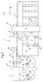
- Fig. 1 shows a schematic plan view of a manufacturing system 1 as a first embodiment of the present invention.
- the manufacturing system 1 comprises a machining center 10 for machining of plate-shaped workpieces 2, which preferably consist predominantly of wood or wood-based materials.
- the machining center 10 has a per se known construction with a first arm 12, which is displaceable along a guide rail 14 in a horizontally extending X-direction.
- On the boom 12, two main spindles 30, 32 are arranged on opposite sides, which are independent of each other in the in Fig. 1 specified Y-direction and in the perpendicular to the plane of Fig. 1 extending Z-direction are movable.
- the first boom 12 extends over a first workpiece table 34, which has an abutment device 36 for positioning workpieces to be machined and a clamping device, not shown, for holding the workpieces to be machined during the machining process.
- the manufacturing system 1 further comprises a loading device 20, which serves to feed the machining center 10 with plate-shaped workpieces 2, which are subsequently machined in the machining center 10, for example.
- the feeder 20 has a second boom 22, which in the present embodiment by three The second boom 22 is connected via its third portion 22 '''to the guide rail 14 so as to be slidable in the horizontally extending X-direction first portion 22 'of the second boom 22 in the present embodiment, a gripping device 24 is provided, which is movable in the Y-direction and in the Z-direction and is adapted to grip the plate-shaped workpieces 2 and release again.
- the gripping device 24 has a plurality of gripping elements 28, which are formed in the present embodiment by vacuum suction. Further, the gripping device 24 has a particularly ausgestaltetes gripping element 28 ', which can be pivoted about a provided with a spring and a stop switch hinge to align the plate-shaped workpieces 2 when depositing can, which will be described later in more detail.
- the third portion 22 "'of the second boom 22 has, at its end facing the machining center 10, an engagement member 18' intended to cooperate with a complementary first engagement member 18 provided on the first arm 12.
- the engagement elements may be, for example, elements that undergo a releasable mechanical engagement with each other, such as a pawl and a bolt. However, the engagement between these elements does not have to take place in a form-fitting manner, but can for example also be non-positive (for example by clamping elements), magnetically or in another suitable manner.
- the manufacturing system 1 according to the invention further comprises a control unit configured to simultaneously control the operation of the machining center 10 and the loading device 20. Using this control unit the operation of the manufacturing system 1 according to the invention takes place, for example, as follows.
- the gripping device 24 is moved over the stack of unprocessed workpieces 2 in the Y and Z directions in such a way that the gripping elements 28, 28 'can grip the upper side of the uppermost plate-shaped workpiece 2.
- the first boom 12 is moved in the direction of the loading device 20 in such a way that the first engagement element 18 and the second engagement element 18 'engage with one another.
- the machining center 10 and the loading device 20 are thus coupled together.
- This unit is now moved by operating the motor 16 along the guide rail 14 such that the workpiece to be machined 2 comes to rest above the workpiece table 34 near a desired processing position.
- the workpiece 2 is deposited by a method of the gripping device 24 on the workpiece table 34, and the gripping elements 28 are released from the workpiece 2, so that the workpiece only with the pivotable gripping element 28 'is in communication.
- the only held by the gripping member 28 'workpiece 2 is further pushed to the stop pin 36 of the workpiece table and thus brought precisely to the desired processing position.
- the gripping element 28 ' is pivoted against the force of the hinge spring (not shown) until a stop switch (not shown) is actuated, which ends the shifting operation.
- the workpiece 2 is held on the workpiece table 34 with a jig not shown in detail.
- the actual machining operation of the workpiece 2 is performed by the machining center 10 using machining tools that are loaded into the main spindles 30 and 32 respectively as needed.
- the machining process can basically also take place, or at least temporarily, with the feeding device 20 coupled to the machining center 10, it is preferred in the context of the present invention for the feeding device to be incorporated into the infeed device before the machining process begins Fig. 1 shown back home position and is released by separating the first and the second engagement element of the machining center 10.
- the feeder 20 is again coupled to the machining center 10 in the manner described above to subsequently receive the processed plate-shaped workpiece 2 'and on a corresponding stack for processed plate-shaped workpieces 2', for example, next to the stack for unprocessed plate-shaped workpieces can be arranged to take off. Thereafter, the loading operation described above starts again to prepare a subsequent machining operation.
- the workpiece table 34 has a plurality of suitable processing positions with corresponding stop elements 36, it is also possible to feed in each traversing movement of the loading device 20 an unprocessed plate-shaped workpiece 2 or to convey a processed plate-shaped workpiece 2 '.
- FIG Fig. 2 A manufacturing system 1 according to a second preferred embodiment of the present invention is shown schematically in FIG Fig. 2 shown.
- the embodiment shown differs from that in FIG Fig. 1 embodiment shown primarily in that the Charging device 20 has two gripping means 24, 26 which are arranged on opposite sides of the second arm 22. This makes it possible for the loading device 20 to deposit two or even more plate-shaped workpieces 2 on the workpiece table 34 during each movement or to pick up corresponding processed workpieces 2 'from the workpiece table 34.
- the operation of the manufacturing system in the second embodiment does not differ from those in the first embodiment.
Landscapes
- Engineering & Computer Science (AREA)
- Mechanical Engineering (AREA)
- Life Sciences & Earth Sciences (AREA)
- Robotics (AREA)
- Wood Science & Technology (AREA)
- Forests & Forestry (AREA)
- Feeding Of Workpieces (AREA)
- Multi-Process Working Machines And Systems (AREA)
- Specific Conveyance Elements (AREA)
Claims (11)
- Système de fabrication (1), comprenant
un centre d'usinage (10) pour un usinage avec enlèvement de copeaux de pièces d'oeuvre (2) en forme de plaques, comprenant un premier bras articulé (12), déplaçable dans une direction X s'étendant horizontalement et présentant une ou plusieurs broches, et
un dispositif de chargement (20) pour charger le centre d'usinage (10) avec des pièces d'oeuvre (2) en forme de plaques, présentant un deuxième bras articulé (22) déplaçable dans la direction X s'étendant horizontalement, et au moins un dispositif de préhension (24, 26) déplaçable dans une direction Y s'étendant horizontalement, le long du deuxième bras articulé (22) et d'une direction Z s'étendant verticalement,
caractérisé en ce que
le premier (12) et le deuxième (22) bras articulés présentent un dispositif de guidage (14) commun, le long duquel ils sont déplaçables dans la direction X et/ou un entraînement (16) commun, au moyen duquel ils sont déplaçables dans la direction X. - Système de fabrication selon la revendication 1, caractérisé en ce que l'entraînement (16) commun est prévu dans le centre d'usinage (10), pour déplacement du premier bras articulé (12) dans la direction X s'étendant horizontalement.
- Système de fabrication selon la revendication 1 ou 2, caractérisé en ce que le premier bras articulé (12) et le deuxième bras articulé (22) sont susceptibles d'être couplés ensemble à l'aide d'un dispositif de couplage (18, 18').
- Système de fabrication selon la revendication 3, caractérisé en ce que le dispositif de couplage présente un premier élément de mise en prise (18) prévu sur le premier bras articulé (12), et un deuxième élément de mise en prise (18') prévu sur le deuxième bras articulé (22).
- Système de fabrication selon l'une des revendications précédentes, caractérisé en ce que le centre d'usinage (10) et le dispositif de chargement (20) présentent une unité de commande commune, agencée pour commander simultanément le fonctionnement du centre d'usinage (10) et du dispositif de chargement (20).
- Système de fabrication selon l'une des revendications précédentes, caractérisé en ce que le au moins un dispositif de préhension (24, 26) est déplaçable dans la direction Y et dans la direction Z, qui s'étendent sensiblement perpendiculairement l'une par rapport à l'autre ainsi que sensiblement perpendiculairement par rapport à la direction X, le déplacement se faisant indépendamment chaque fois des autres directions.
- Système de fabrication selon l'une des revendications précédentes, caractérisé en ce que le deuxième bras articulé (22) présente au moins trois tronçons (22', 22", 22"') allongés, dont chaque fois l'un s'étend dans la direction X, dans la direction Y et dans la direction Z, les directions étant sensiblement perpendiculaires les unes aux autres.
- Système de fabrication selon l'une des revendications précédentes, caractérisé en ce que le au moins un dispositif de préhension (24, 26) présente respectivement une pluralité d'éléments de préhension (28), dont chaque fois au moins l'un (28') est susceptible de pivoter.
- Système de fabrication selon l'une des revendications précédentes, caractérisé en ce que au moins deux dispositifs de préhension (24, 26) sont prévus, disposés, de préférence, sur des côtés opposés du deuxième bras articulé (22).
- Système de fabrication selon l'une des revendications précédentes, caractérisé en ce que le centre d'usinage présente deux broches principales (30, 32), déplaçables indépendamment l'une de l'autre dans la direction Y et dans la direction Z.
- Système de fabrication selon l'une des revendications précédentes, caractérisé en ce que le centre d'usinage présente une table pour pièces d'oeuvre (34) fixe, avec un dispositif de butée (36) et un dispositif de montage par bridage.
Priority Applications (1)
| Application Number | Priority Date | Filing Date | Title |
|---|---|---|---|
| PL06002342T PL1716991T3 (pl) | 2005-04-29 | 2006-02-06 | System produkcyjny do płytowych detali |
Applications Claiming Priority (1)
| Application Number | Priority Date | Filing Date | Title |
|---|---|---|---|
| DE102005020119A DE102005020119B3 (de) | 2005-04-29 | 2005-04-29 | Fertigungssystem |
Publications (2)
| Publication Number | Publication Date |
|---|---|
| EP1716991A1 EP1716991A1 (fr) | 2006-11-02 |
| EP1716991B1 true EP1716991B1 (fr) | 2008-04-09 |
Family
ID=36441981
Family Applications (1)
| Application Number | Title | Priority Date | Filing Date |
|---|---|---|---|
| EP06002342A Expired - Lifetime EP1716991B1 (fr) | 2005-04-29 | 2006-02-06 | Système de fabrication de pièces en forme de plaque |
Country Status (4)
| Country | Link |
|---|---|
| EP (1) | EP1716991B1 (fr) |
| DE (2) | DE102005020119B3 (fr) |
| ES (1) | ES2304742T3 (fr) |
| PL (1) | PL1716991T3 (fr) |
Cited By (1)
| Publication number | Priority date | Publication date | Assignee | Title |
|---|---|---|---|---|
| DE102021125896A1 (de) | 2021-10-06 | 2023-04-06 | Ima Schelling Deutschland Gmbh | Anlage, insbesondere Holzverarbeitungsanlage, zur Bearbeitung und Handhabung von plattenförmigen Werkstücken |
Families Citing this family (15)
| Publication number | Priority date | Publication date | Assignee | Title |
|---|---|---|---|---|
| EP1839883B1 (fr) | 2006-03-08 | 2016-08-24 | Homag Holzbearbeitungssysteme AG | Procédé et dispositif pour imprimer sur des objets en forme de plaque |
| DE502006005293D1 (de) | 2006-08-25 | 2009-12-17 | Homag Holzbearbeitungssysteme | Vorrichtung zum Bemustern von Werkstücken |
| CN101177074B (zh) | 2006-11-07 | 2011-07-20 | 豪迈木材加工系统公司 | 在工件上制作图案的设备及使用该设备制作图案的方法 |
| DE502007002035D1 (de) | 2007-03-27 | 2009-12-31 | Homag Holzbearbeitungssysteme | Verfahren zum Bedrucken eines dreidimensionalen Behälters |
| EP1990150A1 (fr) * | 2007-05-09 | 2008-11-12 | Weeke Bohrsysteme GmbH | Machine d'usinage |
| EP2168714B1 (fr) * | 2008-09-25 | 2013-06-19 | Weeke Bohrsysteme GmbH | Dispositif de transport et d'usinage |
| IT1395016B1 (it) | 2009-06-30 | 2012-09-05 | Biesse Spa | Macchina per la lavorazione di pannelli di legno o simili |
| EP2423134B1 (fr) | 2010-08-25 | 2013-03-13 | Grundner Sondermaschinen GmbH | Dispositif de manipulation de pièces usinées en forme de plaques |
| DE102013216113A1 (de) | 2013-08-14 | 2015-03-05 | Homag Holzbearbeitungssysteme Gmbh | Beschichtungsaggregat |
| CN108381682A (zh) * | 2016-11-14 | 2018-08-10 | 宁波奉化飞天人精密模具设计有限公司 | 一种木料切割运输装置 |
| CN106426421A (zh) * | 2016-11-30 | 2017-02-22 | 嘉善弘欣化工厂(普通合伙) | 一种稳定型建筑木材等距切割装置 |
| DE102017208212A1 (de) | 2017-05-16 | 2018-11-22 | Homag Gmbh | Beschickungsvorrichtung und Beschickungsverfahren |
| CN107097303B (zh) * | 2017-05-18 | 2020-03-27 | 电子科技大学 | 一种用于原始木料加工的位置调整装置 |
| IT201900018485A1 (it) * | 2019-10-10 | 2021-04-10 | Scm Group Spa | Centro di lavoro comprendente un sistema di carico e scarico di pezzi, sistema di carico e scarico di pezzi e metodo di funzionamento di detto centro di lavoro. |
| CN114311168A (zh) * | 2021-12-21 | 2022-04-12 | 唐山市宝珠家具有限公司 | 一种用于家具产品的全自动加工系统及其加工方法 |
Family Cites Families (4)
| Publication number | Priority date | Publication date | Assignee | Title |
|---|---|---|---|---|
| DE59103812D1 (de) * | 1991-04-25 | 1995-01-19 | Ligmatech Maschb Gmbh | Einrichtung zum Handhaben und Bearbeiten von plattenförmigen Werkstücken aus Holz, Kunststoff, Verbundwerkstoffen oder dergleichen. |
| ES2082033T3 (es) * | 1991-05-02 | 1996-03-16 | Ligmatech Maschb Gmbh | Dispositivo para manipular piezas en forma de planchas. |
| DE19601331C1 (de) * | 1996-01-16 | 1996-12-12 | Keusch Siegfried | Maschine zum Bohren, Nuten, Fräsen und Kantenbearbeiten von plattenförmigen Werkstücken aus Holz oder ähnlichen Werkstoffen |
| DE19846819A1 (de) * | 1998-10-10 | 2000-04-13 | Biesse Spa | Plattenbearbeitungsmaschine |
-
2005
- 2005-04-29 DE DE102005020119A patent/DE102005020119B3/de not_active Expired - Fee Related
-
2006
- 2006-02-06 EP EP06002342A patent/EP1716991B1/fr not_active Expired - Lifetime
- 2006-02-06 ES ES06002342T patent/ES2304742T3/es not_active Expired - Lifetime
- 2006-02-06 PL PL06002342T patent/PL1716991T3/pl unknown
- 2006-02-06 DE DE502006000584T patent/DE502006000584D1/de not_active Expired - Lifetime
Cited By (2)
| Publication number | Priority date | Publication date | Assignee | Title |
|---|---|---|---|---|
| DE102021125896A1 (de) | 2021-10-06 | 2023-04-06 | Ima Schelling Deutschland Gmbh | Anlage, insbesondere Holzverarbeitungsanlage, zur Bearbeitung und Handhabung von plattenförmigen Werkstücken |
| EP4163068A1 (fr) | 2021-10-06 | 2023-04-12 | IMA Schelling Deutschland GmbH | Installation, en particulier installation de traitement du bois, pour l'usinage et la manipulation de pièces en forme de plaques |
Also Published As
| Publication number | Publication date |
|---|---|
| DE502006000584D1 (de) | 2008-05-21 |
| ES2304742T3 (es) | 2008-10-16 |
| PL1716991T3 (pl) | 2008-09-30 |
| EP1716991A1 (fr) | 2006-11-02 |
| DE102005020119B3 (de) | 2006-06-08 |
Similar Documents
| Publication | Publication Date | Title |
|---|---|---|
| EP1716991B1 (fr) | Système de fabrication de pièces en forme de plaque | |
| EP1960155B1 (fr) | Machine-outil | |
| EP3600798A1 (fr) | Système de préhension et de positionnement servant au transport d'un dispositif de serrage entre différentes positions | |
| DE102018103870A1 (de) | Handhabungseinrichtung, Verfahren zum Betreiben einer Handhabungseinrichtung, Werkstückbearbeitungsanlage sowie Bewegungseinrichtung | |
| EP3231552B1 (fr) | Dispositif de positionnement de pièces pour un centre d'usinage, centre d'usinage et procédé | |
| EP0440318B1 (fr) | Manipulateur et procédé de manipulation de pièces | |
| EP2098343B1 (fr) | Dispositif de traitement | |
| DE60219267T2 (de) | Greifeinheit für die automatisierte Bearbeitung von Werkstücken, und Vorrichtung und Verfahren mit einer solchen Einheit | |
| EP0111046A2 (fr) | Dispositif de changement d'outil pour une machine-outil à broches multiples | |
| EP2881219A1 (fr) | Dispositif de changement d'outil destiné à être utilisé dans un centre d'usinage et centre d'usinage destiné à l'usinage mécanique d'une pièce à usiner | |
| EP3124170A1 (fr) | Magasin a chaine pour la reception d'outils | |
| DE102010024321A1 (de) | Maschine zum Bearbeiten von Teilen aus Holz oder dergleichen | |
| EP4257313A2 (fr) | Installation de division de plaques pour diviser des pièces en forme de plaque et procédé pour faire fonctionner celle-ci | |
| EP0913225B1 (fr) | Centre d'usinage dans lequel les porte-pièces sont pourvus d'une connexion multiple avec couvercle | |
| EP3663035A1 (fr) | Machine-outil dotée d'une broche porte-outil et d'un portique de chargement | |
| DE4111545A1 (de) | Rundtaktautomat | |
| EP3362201B1 (fr) | Procédé de fonctionnement d'une presseur plieuse et presse plieuse | |
| EP0637277B1 (fr) | Dispositif pour l'usinage de metaux par enlevement de copeaux | |
| EP0923427B1 (fr) | Machine d'usinage | |
| EP0913226B1 (fr) | Centre d'usinage dans lequel les porte-pièces sont pourvus d'un module de couplage ainsi que d'une connexion multiple | |
| DE102018105661A1 (de) | Beförderungssystem | |
| EP0255567A1 (fr) | Changeur d'outils pour machine universelle à percer et à fraiser | |
| EP3431223B1 (fr) | Procédé d'usinage des pièces à usiner et machine-outil destinée à la mise en oeuvre dudit procédé | |
| EP1645379B1 (fr) | Procédé et centre d'usinage pour l'usinage de pièces en forme de plaque | |
| DE202010000935U1 (de) | Vorrichtung zum Bearbeiten von Werkstücken |
Legal Events
| Date | Code | Title | Description |
|---|---|---|---|
| PUAI | Public reference made under article 153(3) epc to a published international application that has entered the european phase |
Free format text: ORIGINAL CODE: 0009012 |
|
| AK | Designated contracting states |
Kind code of ref document: A1 Designated state(s): AT BE BG CH CY CZ DE DK EE ES FI FR GB GR HU IE IS IT LI LT LU LV MC NL PL PT RO SE SI SK TR |
|
| AX | Request for extension of the european patent |
Extension state: AL BA HR MK YU |
|
| 17P | Request for examination filed |
Effective date: 20061115 |
|
| AKX | Designation fees paid |
Designated state(s): DE ES FR IT PL |
|
| GRAP | Despatch of communication of intention to grant a patent |
Free format text: ORIGINAL CODE: EPIDOSNIGR1 |
|
| GRAS | Grant fee paid |
Free format text: ORIGINAL CODE: EPIDOSNIGR3 |
|
| GRAA | (expected) grant |
Free format text: ORIGINAL CODE: 0009210 |
|
| AK | Designated contracting states |
Kind code of ref document: B1 Designated state(s): DE ES FR IT PL |
|
| REF | Corresponds to: |
Ref document number: 502006000584 Country of ref document: DE Date of ref document: 20080521 Kind code of ref document: P |
|
| REG | Reference to a national code |
Ref country code: PL Ref legal event code: T3 |
|
| REG | Reference to a national code |
Ref country code: ES Ref legal event code: FG2A Ref document number: 2304742 Country of ref document: ES Kind code of ref document: T3 |
|
| ET | Fr: translation filed | ||
| PLBE | No opposition filed within time limit |
Free format text: ORIGINAL CODE: 0009261 |
|
| STAA | Information on the status of an ep patent application or granted ep patent |
Free format text: STATUS: NO OPPOSITION FILED WITHIN TIME LIMIT |
|
| 26N | No opposition filed |
Effective date: 20090112 |
|
| PGFP | Annual fee paid to national office [announced via postgrant information from national office to epo] |
Ref country code: PL Payment date: 20110104 Year of fee payment: 6 |
|
| PGFP | Annual fee paid to national office [announced via postgrant information from national office to epo] |
Ref country code: FR Payment date: 20120307 Year of fee payment: 7 |
|
| REG | Reference to a national code |
Ref country code: FR Ref legal event code: ST Effective date: 20131031 |
|
| PG25 | Lapsed in a contracting state [announced via postgrant information from national office to epo] |
Ref country code: FR Free format text: LAPSE BECAUSE OF NON-PAYMENT OF DUE FEES Effective date: 20130228 |
|
| PG25 | Lapsed in a contracting state [announced via postgrant information from national office to epo] |
Ref country code: PL Free format text: LAPSE BECAUSE OF NON-PAYMENT OF DUE FEES Effective date: 20130206 |
|
| REG | Reference to a national code |
Ref country code: PL Ref legal event code: LAPE |
|
| PGFP | Annual fee paid to national office [announced via postgrant information from national office to epo] |
Ref country code: ES Payment date: 20150121 Year of fee payment: 10 |
|
| PG25 | Lapsed in a contracting state [announced via postgrant information from national office to epo] |
Ref country code: ES Free format text: LAPSE BECAUSE OF NON-PAYMENT OF DUE FEES Effective date: 20160207 |
|
| REG | Reference to a national code |
Ref country code: ES Ref legal event code: FD2A Effective date: 20180626 |
|
| PGFP | Annual fee paid to national office [announced via postgrant information from national office to epo] |
Ref country code: IT Payment date: 20220222 Year of fee payment: 17 |
|
| PGFP | Annual fee paid to national office [announced via postgrant information from national office to epo] |
Ref country code: DE Payment date: 20220615 Year of fee payment: 18 |
|
| P01 | Opt-out of the competence of the unified patent court (upc) registered |
Effective date: 20230529 |
|
| PG25 | Lapsed in a contracting state [announced via postgrant information from national office to epo] |
Ref country code: IT Free format text: LAPSE BECAUSE OF NON-PAYMENT OF DUE FEES Effective date: 20230206 |
|
| REG | Reference to a national code |
Ref country code: DE Ref legal event code: R119 Ref document number: 502006000584 Country of ref document: DE |
|
| PG25 | Lapsed in a contracting state [announced via postgrant information from national office to epo] |
Ref country code: DE Free format text: LAPSE BECAUSE OF NON-PAYMENT OF DUE FEES Effective date: 20240903 |
|
| PG25 | Lapsed in a contracting state [announced via postgrant information from national office to epo] |
Ref country code: DE Free format text: LAPSE BECAUSE OF NON-PAYMENT OF DUE FEES Effective date: 20240903 |