EP1717761A2 - Cylindre de serrure pour une clé comportant un code secret électronique - Google Patents
Cylindre de serrure pour une clé comportant un code secret électronique Download PDFInfo
- Publication number
- EP1717761A2 EP1717761A2 EP06112830A EP06112830A EP1717761A2 EP 1717761 A2 EP1717761 A2 EP 1717761A2 EP 06112830 A EP06112830 A EP 06112830A EP 06112830 A EP06112830 A EP 06112830A EP 1717761 A2 EP1717761 A2 EP 1717761A2
- Authority
- EP
- European Patent Office
- Prior art keywords
- lock cylinder
- key
- antenna
- particular according
- core
- Prior art date
- Legal status (The legal status is an assumption and is not a legal conclusion. Google has not performed a legal analysis and makes no representation as to the accuracy of the status listed.)
- Granted
Links
Images




Classifications
-
- E—FIXED CONSTRUCTIONS
- E05—LOCKS; KEYS; WINDOW OR DOOR FITTINGS; SAFES
- E05B—LOCKS; ACCESSORIES THEREFOR; HANDCUFFS
- E05B47/00—Operating or controlling locks or other fastening devices by electric or magnetic means
- E05B47/06—Controlling mechanically-operated bolts by electro-magnetically-operated detents
- E05B47/0611—Cylinder locks with electromagnetic control
- E05B47/0638—Cylinder locks with electromagnetic control by disconnecting the rotor
-
- E—FIXED CONSTRUCTIONS
- E05—LOCKS; KEYS; WINDOW OR DOOR FITTINGS; SAFES
- E05B—LOCKS; ACCESSORIES THEREFOR; HANDCUFFS
- E05B47/00—Operating or controlling locks or other fastening devices by electric or magnetic means
- E05B47/06—Controlling mechanically-operated bolts by electro-magnetically-operated detents
- E05B47/0611—Cylinder locks with electromagnetic control
- E05B47/0615—Cylinder locks with electromagnetic control operated by handles, e.g. by knobs
-
- G—PHYSICS
- G07—CHECKING-DEVICES
- G07C—TIME OR ATTENDANCE REGISTERS; REGISTERING OR INDICATING THE WORKING OF MACHINES; GENERATING RANDOM NUMBERS; VOTING OR LOTTERY APPARATUS; ARRANGEMENTS, SYSTEMS OR APPARATUS FOR CHECKING NOT PROVIDED FOR ELSEWHERE
- G07C9/00—Individual registration on entry or exit
- G07C9/00174—Electronically operated locks; Circuits therefor; Nonmechanical keys therefor, e.g. passive or active electrical keys or other data carriers without mechanical keys
- G07C9/00944—Details of construction or manufacture
Definitions
- the invention relates to a lock cylinder with a housing and a stored in an end face of the housing bearing cavity, a keyway for inserting the cam of a key having cylinder core, which is rotatable relative to the housing at least in the keyway mating key, and with a closing member for Output of the rotational movement of the matching key, wherein the key is carrier of an electronic secret of secrecy, which is readable by means of an arranged on the front side of the lock cylinder antenna.
- Such a lock cylinder is out of the DE 103 29 414 A1 previously known.
- One of the two cylinder halves is equipped with a cylinder core, in which a key shank of a flat key can be inserted.
- the cylinder core has a row of successively arranged holes. Core pins are located in these core pin holes. In the locking position of the cylinder, the core holes are aligned with housing bores in which housing pins eino, which are acted upon by means of tumbler springs in the direction of the core. In the blocking position, the housing pins protrude in areas in the core holes, so that the cylinder core is rotationally locked.
- this lock cylinder has a tumbler pin which is electromagnetically actuated.
- the electromagnet releases the displacement of this additional tumbler pin from a locking position to a release position when a transponder arranged in the ridge of the key has the correct electronic locking secret.
- the latter is interrogated by means of an antenna which is arranged in the region of the end face of the housing of the lock cylinder is.
- the second half of the double lock cylinder also has a core. This is like the previously described core with a closing member rotatably coupled. However, no tumblers are provided there. On the core rather sits a knob in which an electronic circuit is arranged, which is electrically connected to the antenna to read the secret of secrecy from the transponder and to cause the electromagnet to release the locking pin.
- the invention has for its object to further develop the generic lock cylinder nutzsvorteilhaft.
- each claim is basically an independent solution to the problem and each claim can be combined with any other claim in any combination.
- Claim 1 initially and essentially provides that the antenna is associated with a rotationally fixed manner to the cylinder core antenna carrier. Unlike the prior art, the antenna is now not assigned to the housing, but the cylinder core. It therefore rotates when the cylinder core is turned by the key.
- the antenna carrier can be plugged onto a profile extension of the cylinder core.
- the antenna carrier may extend with an extension over a portion of the flange portion of the housing. For this purpose, the end face of the housing form a recess which receives the extension in the key withdrawal position. If the key is turned, this extension rotates.
- the extension of the antenna carrier may lie in the key withdrawal position in front of a step of the flange portion.
- the radially outwardly facing end face of the antenna carrier which extends on a peripheral surface about the axis of rotation of the core, may have connection contacts. For example, via these connectors an emergency power supply.
- the antenna carrier may carry an antenna formed by a coil. This can surround the key channel. But it is also envisaged that this antenna rests in the extension of the antenna carrier. On the other hand, however, the coil forming the antenna can also extend over the entire circumferential contour of the antenna carrier, that is to say projecting around almost the entire end face of the antenna carrier. It is also possible that the antenna is a ferrite antenna. This can be in the region of the end face of the core or else in the extension.
- the cylinder core is positively connected to the antenna carrier.
- the profile projection which forms the end face of the cylinder core, is preferably clipped into a corresponding recess of the antenna carrier. This profile projection also serves as a stop for the key inserted in the keyway. This key has a known stop shoulder which hits directly on the metal of the core.
- the antenna carrier is preferably made of plastic.
- the cylinder core is locked in rotation exclusively by means of mechanically actuated tumblers. These are those in the generic DE 103 29 414 A1 described tumbler.
- the lock cylinder can be turned. This can be done independently of the accuracy of the electronic key secret or at least even if an internal power supply of the lock cylinder is defective. However, a rotational drive of the closing member is nevertheless prevented by the cylinder core that can be actuated when the electronic key secret is incorrect or the internal power supply is defective. In particular, in the case of an empty battery, which is arranged, for example, in the knob of the lock cylinder, this rotation of the lock cylinder offers advantages. On the front of the Antenna carrier, which is normally covered by the stage of the housing, there may be connection contacts with which the lock cylinder is notbestrombar.
- the closing element is momentarily coupled in a rotational manner to the cylinder core so that a rotation of the key also leads to a rotation of the closing element, so that the lock in which the closing cylinder is inserted can be opened.
- the basic structure of a lock cylinder is in the DE 103 29 414 A1 described in detail, which is why at this point not discussed in detail.
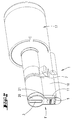
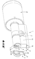
- the lock cylinder shown in the drawings has a cylinder core 6, which has a key channel 3.
- the shaft 19 of a key 5 can be inserted.
- the shaft 19 of the key has recesses, either as in the DE 103 29 414 as notches, or as shown in Fig. 8 may be formed as wells. These recesses arranged in the cylinder core 6, not shown Kernzu insectss foreste sorted.
- the end faces of the core pins are aligned with the parting plane of the cylinder core and the wall of the bearing cavity 2 for the cylinder core 6, so that the cylinder core 6 is rotated within the bearing cavity 2 of the housing 1 can be.
- the housing has in a known manner to the core holes of the cylinder core aligned housing bores, in which housing pins stuck, which are cushioned in the direction of the core with tumbler springs.
- the lock cylinder also has a coupling with which the cylinder core 6 can be rotatably coupled to the closing member 7.
- the coupling can be actuated electromagnetically or electrostatically.
- the cylinder core 6 is not rotationally coupled to the closing member 7.
- a knob 17 is navgekuppelt, which is located on the inside of the door and in which, for example, a battery and an electronic circuit can be located.
- the electronic circuit is connected via not shown electrical lines, eg. Via a multi-core cable with the front side 1 'of the lock cylinder.
- a step 13 of the bottom portion of the flange portion 11 forms a recess 12.
- the front side of the cylinder core 6 has a metal profile projection 16 extending around the key channel 3.
- the section of the end faces of the cylinder core 6 set back from the profile projection 16 lies in a plane with the bottom of the recess 12.
- An antenna carrier 9 can be clipped onto the profile projection 16 .
- the antenna carrier 9 is, as can be seen from FIGS. 4 and 5, a plastic cap which has a retaining collar 22 which can be slipped over the profile projection 16.
- an edge collar 23 extends, so that within the antenna carrier 9, a cavity 24 is formed. This cavity 24 serves to receive an antenna.
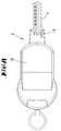
- FIG. 3 shows by way of example a multiplicity of differently configured antennas.
- an antenna 8 ' may be assigned to the recess 11 in the recess 11 of the antenna carrier 9. It is also possible to have a coil 8 to arrange the keyway 3 around. This coil then extends around the retaining collar 22 at the inner edge of the edge collar 23. But it is also possible to arrange ferrite antennas 15 within the antenna carrier 9. These ferrite antennas 15 can be arranged in the region of the extension 11 or else next to the key channel 3.
- the reference numeral 25 designates openings in the area of an end face of the extension 11 pointing radially outwards. In the key withdrawal position (FIG. 2), this end face is covered by the step 13, so that the connection contacts 14 inserted in the openings 25 are not accessible.
- the connection contacts 14 serve an emergency power supply and are electrically conductively connected to the battery or other suitable units which are arranged in the knob 17.
- the front side of the antenna carrier 9 has two recesses 20 'and 21', in which plates 20 and 21 are einklebbar.
- the plate 21 has a circular shape and serves to receive a label.
- the plate 20 has a diametrical slot and surrounds the keyway 3 on three sides.
- the operation of the lock cylinder is the following:
- the tumbler pins are sorted in a known manner. If it is a matching key, the cylinder core 6 can be rotated. However, a rotational drive of the closing member 7 is only provided if the key additionally has a suitable electronic key secret. This electronic key secret is kept in the key 18 in a transponder existing there. Within the closing knob is an electronic circuit, via the antenna 8, 8 ', 15 the transponder influenced to send its key secret to the antenna where it is received, and to the electronic circuit within the knob 17 is forwarded. If an electronic control unit located there detects the correctness of the key secret, the closing element 7 is rotationally coupled to the cylinder core 6, so that a lock in which the lock cylinder is inserted can be actuated.
- the transponder In order to cause the transponder to send its key secret, it is necessary in individual cases to wake it up. This is done by sending an alternating electromagnetic field through the antenna 8, which provides the transponder with the energy required for sending the key secret.
- the transmission of the wake-up signal can be initiated by inserting the key into the key channel 3. But it is also possible that the transmission of this signal by an initial rotation of the key is set in motion.
- an active transponder can be used, which has its own power supply.
- transponders can be used, which interact via a special protocol with a transceiver within the knob via the antenna.
- encrypted data can be transmitted in a suitable manner in order to carry out the identification of the key by way of a question-answer algorithm.
- a self-sufficient lock cylinder which carries its own power supply, eg. In the form of a battery in the knob 17. If the case occurs that this battery is empty, the lock cylinder can still be operated by a suitable key. The mechanically fitting key is inserted into the closing channel 3. As a result, the Cylinder 6 can be rotated. As a result, the connection contacts 14 come out of their hiding position and can be connected to the emergency power supply of the lock cylinder with a power source. The then set in progress interrogator determines the electronic key secret of the key and coupled with the right secret, the closing member 7 with the cylinder core. 6
- the invention also includes such lock cylinder, which has an additional, electromagnetically activatable tumbler for the cylinder core 6, as shown in the DE 103 29 414 A1 is already known.
- the cylinder core can only be rotated or only fully rotated if the correct electronic key secret of the key 5 has previously been recognized.
- the shape of the key 18 can be formed as shown in Figures 6 to 9. In this case, the Raide 18 from the DE 103 29 414 Her known form, or having a shape shown in Fig. 7 without extension.
- the transponder is also removed in the case of the key 18 shown in FIG. 8 by a certain distance from the antenna 8.
Landscapes
- Physics & Mathematics (AREA)
- Electromagnetism (AREA)
- Engineering & Computer Science (AREA)
- Manufacturing & Machinery (AREA)
- General Physics & Mathematics (AREA)
- Lock And Its Accessories (AREA)
Applications Claiming Priority (1)
| Application Number | Priority Date | Filing Date | Title |
|---|---|---|---|
| DE200510019170 DE102005019170A1 (de) | 2005-04-25 | 2005-04-25 | Schließzylinder für einen ein elektronisches Schließgeheimnis tragenden Schlüssel |
Publications (3)
| Publication Number | Publication Date |
|---|---|
| EP1717761A2 true EP1717761A2 (fr) | 2006-11-02 |
| EP1717761A3 EP1717761A3 (fr) | 2006-12-06 |
| EP1717761B1 EP1717761B1 (fr) | 2010-07-28 |
Family
ID=36617119
Family Applications (1)
| Application Number | Title | Priority Date | Filing Date |
|---|---|---|---|
| EP20060112830 Expired - Fee Related EP1717761B1 (fr) | 2005-04-25 | 2006-04-20 | Cylindre de serrure pour une clé comportant un code secret électronique |
Country Status (2)
| Country | Link |
|---|---|
| EP (1) | EP1717761B1 (fr) |
| DE (2) | DE102005019170A1 (fr) |
Cited By (6)
| Publication number | Priority date | Publication date | Assignee | Title |
|---|---|---|---|---|
| CN101963009A (zh) * | 2010-11-05 | 2011-02-02 | 林挺意 | 电子密码锁 |
| WO2011011803A1 (fr) * | 2009-07-27 | 2011-02-03 | Evva Sicherheitstechnologie Gmbh | Unité de lecture et/ou d'écriture de supports d'identité |
| WO2014071920A3 (fr) * | 2012-11-12 | 2014-07-10 | Assa Abloy Sicherheitstechnik Gmbh | Barillet |
| DE102015105412B3 (de) * | 2015-04-09 | 2016-07-07 | Assa Abloy Sicherheitstechnik Gmbh | Schließzylinder |
| EP2708681A3 (fr) * | 2012-09-12 | 2017-10-18 | Aug. Winkhaus GmbH & Co. KG | Cylindre de fermeture pour une clé électronique |
| EP3832521A1 (fr) * | 2019-12-04 | 2021-06-09 | Netatmo | Serrure intelligente présentant une clé électromécanique |
Families Citing this family (2)
| Publication number | Priority date | Publication date | Assignee | Title |
|---|---|---|---|---|
| DE102008037376A1 (de) | 2008-09-22 | 2010-03-25 | Cestronics Gmbh | Schloss, insbesondere Schließzylinder mit einer Einrichtung zur Kommunikation mit einem Transponder und Kommunikationseinrichtung |
| CN103761788B (zh) * | 2014-01-20 | 2015-12-30 | 林挺意 | 双向通信密码锁 |
Citations (1)
| Publication number | Priority date | Publication date | Assignee | Title |
|---|---|---|---|---|
| DE10329414A1 (de) | 2003-07-01 | 2005-01-20 | C. Ed. Schulte Gmbh Zylinderschlossfabrik | Schließvorrichtung |
Family Cites Families (3)
| Publication number | Priority date | Publication date | Assignee | Title |
|---|---|---|---|---|
| US5117097A (en) * | 1990-02-27 | 1992-05-26 | Kabushiki Kaisha Tokai Rika Denki Seisakusho | Key system for a vehicle |
| JP2565632Y2 (ja) * | 1993-06-08 | 1998-03-18 | 株式会社東海理化電機製作所 | キーシリンダ装置 |
| DE10115074A1 (de) * | 2001-03-27 | 2002-10-02 | Winkhaus Fa August | Schließzylinder |
-
2005
- 2005-04-25 DE DE200510019170 patent/DE102005019170A1/de not_active Withdrawn
-
2006
- 2006-04-20 EP EP20060112830 patent/EP1717761B1/fr not_active Expired - Fee Related
- 2006-04-20 DE DE200650007515 patent/DE502006007515D1/de not_active Expired - Lifetime
Patent Citations (1)
| Publication number | Priority date | Publication date | Assignee | Title |
|---|---|---|---|---|
| DE10329414A1 (de) | 2003-07-01 | 2005-01-20 | C. Ed. Schulte Gmbh Zylinderschlossfabrik | Schließvorrichtung |
Cited By (8)
| Publication number | Priority date | Publication date | Assignee | Title |
|---|---|---|---|---|
| WO2011011803A1 (fr) * | 2009-07-27 | 2011-02-03 | Evva Sicherheitstechnologie Gmbh | Unité de lecture et/ou d'écriture de supports d'identité |
| CN101963009A (zh) * | 2010-11-05 | 2011-02-02 | 林挺意 | 电子密码锁 |
| CN101963009B (zh) * | 2010-11-05 | 2012-07-25 | 林挺意 | 电子密码锁 |
| EP2708681A3 (fr) * | 2012-09-12 | 2017-10-18 | Aug. Winkhaus GmbH & Co. KG | Cylindre de fermeture pour une clé électronique |
| WO2014071920A3 (fr) * | 2012-11-12 | 2014-07-10 | Assa Abloy Sicherheitstechnik Gmbh | Barillet |
| DE102015105412B3 (de) * | 2015-04-09 | 2016-07-07 | Assa Abloy Sicherheitstechnik Gmbh | Schließzylinder |
| EP3085861A1 (fr) * | 2015-04-09 | 2016-10-26 | ASSA ABLOY Sicherheitstechnik GmbH | Barillet |
| EP3832521A1 (fr) * | 2019-12-04 | 2021-06-09 | Netatmo | Serrure intelligente présentant une clé électromécanique |
Also Published As
| Publication number | Publication date |
|---|---|
| EP1717761B1 (fr) | 2010-07-28 |
| DE502006007515D1 (de) | 2010-09-09 |
| DE102005019170A1 (de) | 2006-10-26 |
| EP1717761A3 (fr) | 2006-12-06 |
Similar Documents
| Publication | Publication Date | Title |
|---|---|---|
| EP0743411B2 (fr) | Dispositif de fermeture | |
| EP2415028B1 (fr) | Dispositif de fermeture mécatronique | |
| EP2201535B1 (fr) | Dispositif de verrouillage | |
| DE3610788C2 (de) | Schlüssel und dazugehöriges Schloß | |
| DE19807577C1 (de) | Schließvorrichtung | |
| EP1214491B1 (fr) | Unite de verrouillage pour une serrure a barillet | |
| EP1065335B1 (fr) | Système de verrouillage électromécanique | |
| EP1256671B1 (fr) | Rosette pour serrure cylindrique | |
| EP0559158A1 (fr) | Cylindre de fermeture électronique | |
| DE3632904A1 (de) | Schliesseinrichtung fuer ein mechanisch/elektronisches schliess-system | |
| EP1717761B1 (fr) | Cylindre de serrure pour une clé comportant un code secret électronique | |
| EP0224607A1 (fr) | Dispositif de fermeture comportant un système électronique d'identification | |
| DE102006045195B3 (de) | Codeeingabeeinheit für elektronische Schließzylinder | |
| EP1736622B2 (fr) | Barillet | |
| EP1174572A2 (fr) | Serrure cylindrique disposant d'un agencement pour la transmission de signal sans contact | |
| DE4314903A1 (de) | Schloßanordnung | |
| EP3889918B1 (fr) | Cylindre de fermeture pour une machine automatique de jeu, machine automatique de jeu et procédé | |
| EP1716544B1 (fr) | Cylindre de fermeture profile pour augmenter la securite de transmission et la securite contre les interferences au cours de la mise a disposition de donnees au moyen de reseaux sans fil, en particulier a haute frequence, pour commander, programmer, surveiller et evaluer des installations | |
| EP2706173B1 (fr) | Dispositif de verrouillage comportant des moyens de liaison présentant des contacts électriques et des contre-contacts | |
| EP0915220B1 (fr) | Système de verrouillage mécanique et électronique | |
| EP3626919A1 (fr) | Poignée de commande pourvue de système de contrôle d'accès | |
| DE10131280A1 (de) | Wendeschlüssel | |
| DE202004013906U1 (de) | Beschlagsatz | |
| CH718481A1 (de) | Mechatronischer Schlüssel. | |
| EP3131068A1 (fr) | Verrou de porte d'armoire en communication sans fil avec une unite centrale |
Legal Events
| Date | Code | Title | Description |
|---|---|---|---|
| PUAI | Public reference made under article 153(3) epc to a published international application that has entered the european phase |
Free format text: ORIGINAL CODE: 0009012 |
|
| AK | Designated contracting states |
Kind code of ref document: A2 Designated state(s): AT BE BG CH CY CZ DE DK EE ES FI FR GB GR HU IE IS IT LI LT LU LV MC NL PL PT RO SE SI SK TR |
|
| AX | Request for extension of the european patent |
Extension state: AL BA HR MK YU |
|
| PUAL | Search report despatched |
Free format text: ORIGINAL CODE: 0009013 |
|
| AK | Designated contracting states |
Kind code of ref document: A3 Designated state(s): AT BE BG CH CY CZ DE DK EE ES FI FR GB GR HU IE IS IT LI LT LU LV MC NL PL PT RO SE SI SK TR |
|
| AX | Request for extension of the european patent |
Extension state: AL BA HR MK YU |
|
| 17P | Request for examination filed |
Effective date: 20070604 |
|
| AKX | Designation fees paid |
Designated state(s): DE NL |
|
| 17Q | First examination report despatched |
Effective date: 20070919 |
|
| GRAP | Despatch of communication of intention to grant a patent |
Free format text: ORIGINAL CODE: EPIDOSNIGR1 |
|
| GRAS | Grant fee paid |
Free format text: ORIGINAL CODE: EPIDOSNIGR3 |
|
| GRAA | (expected) grant |
Free format text: ORIGINAL CODE: 0009210 |
|
| AK | Designated contracting states |
Kind code of ref document: B1 Designated state(s): DE NL |
|
| REF | Corresponds to: |
Ref document number: 502006007515 Country of ref document: DE Date of ref document: 20100909 Kind code of ref document: P |
|
| REG | Reference to a national code |
Ref country code: NL Ref legal event code: T3 |
|
| PLBE | No opposition filed within time limit |
Free format text: ORIGINAL CODE: 0009261 |
|
| STAA | Information on the status of an ep patent application or granted ep patent |
Free format text: STATUS: NO OPPOSITION FILED WITHIN TIME LIMIT |
|
| 26N | No opposition filed |
Effective date: 20110429 |
|
| PGFP | Annual fee paid to national office [announced via postgrant information from national office to epo] |
Ref country code: DE Payment date: 20101229 Year of fee payment: 6 |
|
| REG | Reference to a national code |
Ref country code: DE Ref legal event code: R097 Ref document number: 502006007515 Country of ref document: DE Effective date: 20110429 |
|
| PGFP | Annual fee paid to national office [announced via postgrant information from national office to epo] |
Ref country code: NL Payment date: 20110420 Year of fee payment: 6 |
|
| REG | Reference to a national code |
Ref country code: NL Ref legal event code: V1 Effective date: 20121101 |
|
| REG | Reference to a national code |
Ref country code: DE Ref legal event code: R119 Ref document number: 502006007515 Country of ref document: DE Effective date: 20121101 |
|
| PG25 | Lapsed in a contracting state [announced via postgrant information from national office to epo] |
Ref country code: NL Free format text: LAPSE BECAUSE OF NON-PAYMENT OF DUE FEES Effective date: 20121101 |
|
| PG25 | Lapsed in a contracting state [announced via postgrant information from national office to epo] |
Ref country code: DE Free format text: LAPSE BECAUSE OF NON-PAYMENT OF DUE FEES Effective date: 20121101 |