EP1721577A1 - Instrument endoscopique - Google Patents
Instrument endoscopique Download PDFInfo
- Publication number
- EP1721577A1 EP1721577A1 EP06008584A EP06008584A EP1721577A1 EP 1721577 A1 EP1721577 A1 EP 1721577A1 EP 06008584 A EP06008584 A EP 06008584A EP 06008584 A EP06008584 A EP 06008584A EP 1721577 A1 EP1721577 A1 EP 1721577A1
- Authority
- EP
- European Patent Office
- Prior art keywords
- pull
- push rod
- medical instrument
- handle
- instrument according
- Prior art date
- Legal status (The legal status is an assumption and is not a legal conclusion. Google has not performed a legal analysis and makes no representation as to the accuracy of the status listed.)
- Granted
Links
- 230000033001 locomotion Effects 0.000 claims description 23
- 230000005540 biological transmission Effects 0.000 description 6
- 238000006073 displacement reaction Methods 0.000 description 3
- 238000006243 chemical reaction Methods 0.000 description 2
- 238000005452 bending Methods 0.000 description 1
- 230000015572 biosynthetic process Effects 0.000 description 1
- 230000006866 deterioration Effects 0.000 description 1
- 238000002674 endoscopic surgery Methods 0.000 description 1
- 230000000977 initiatory effect Effects 0.000 description 1
- 238000004519 manufacturing process Methods 0.000 description 1
Images


Classifications
-
- A—HUMAN NECESSITIES
- A61—MEDICAL OR VETERINARY SCIENCE; HYGIENE
- A61B—DIAGNOSIS; SURGERY; IDENTIFICATION
- A61B17/00—Surgical instruments, devices or methods
- A61B17/28—Surgical forceps
- A61B17/29—Forceps for use in minimally invasive surgery
-
- A—HUMAN NECESSITIES
- A61—MEDICAL OR VETERINARY SCIENCE; HYGIENE
- A61B—DIAGNOSIS; SURGERY; IDENTIFICATION
- A61B17/00—Surgical instruments, devices or methods
- A61B17/04—Surgical instruments, devices or methods for suturing wounds; Holders or packages for needles or suture materials
- A61B17/0483—Hand-held instruments for holding sutures
-
- A—HUMAN NECESSITIES
- A61—MEDICAL OR VETERINARY SCIENCE; HYGIENE
- A61B—DIAGNOSIS; SURGERY; IDENTIFICATION
- A61B17/00—Surgical instruments, devices or methods
- A61B17/16—Instruments for performing osteoclasis; Drills or chisels for bones; Trepans
- A61B17/1604—Chisels; Rongeurs; Punches; Stamps
- A61B17/1606—Chisels; Rongeurs; Punches; Stamps of forceps type, i.e. having two jaw elements moving relative to each other
- A61B17/1608—Chisels; Rongeurs; Punches; Stamps of forceps type, i.e. having two jaw elements moving relative to each other the two jaw elements being linked to two elongated shaft elements moving longitudinally relative to each other
-
- A—HUMAN NECESSITIES
- A61—MEDICAL OR VETERINARY SCIENCE; HYGIENE
- A61B—DIAGNOSIS; SURGERY; IDENTIFICATION
- A61B17/00—Surgical instruments, devices or methods
- A61B2017/00681—Aspects not otherwise provided for
- A61B2017/00685—Archimedes screw
-
- A—HUMAN NECESSITIES
- A61—MEDICAL OR VETERINARY SCIENCE; HYGIENE
- A61B—DIAGNOSIS; SURGERY; IDENTIFICATION
- A61B17/00—Surgical instruments, devices or methods
- A61B17/28—Surgical forceps
- A61B17/29—Forceps for use in minimally invasive surgery
- A61B2017/2926—Details of heads or jaws
- A61B2017/2932—Transmission of forces to jaw members
- A61B2017/2933—Transmission of forces to jaw members camming or guiding means
-
- A—HUMAN NECESSITIES
- A61—MEDICAL OR VETERINARY SCIENCE; HYGIENE
- A61B—DIAGNOSIS; SURGERY; IDENTIFICATION
- A61B17/00—Surgical instruments, devices or methods
- A61B17/28—Surgical forceps
- A61B17/29—Forceps for use in minimally invasive surgery
- A61B2017/2926—Details of heads or jaws
- A61B2017/2932—Transmission of forces to jaw members
- A61B2017/2933—Transmission of forces to jaw members camming or guiding means
- A61B2017/2936—Pins in guiding slots
Definitions
- the invention relates to a medical instrument with a hollow shaft, at the proximal end of which a handle consisting of at least two handle parts is arranged and at the distal end of which consists of at least two jaws tool is arranged, wherein at least one jaw part of the tool for opening and closing over a pivotable designed grip part of the handle relative to the at least one other jaw part of the tool is adjustable and the at least one adjustable jaw part and the corresponding, serving for adjusting the jaw part handle part of the handle via an axially displaceable in the hollow shaft mounted pull / push rod are connected together ,
- the invention has for its object to provide a medical instrument of the aforementioned type, in which the conversion of the axial movement of the push / pull rod easily and reliably into the rotational movement of the adjustable jaw part.
- the solution to this problem is inventively characterized in that the axially displaceable mounted in the hollow shaft pull / push rod via at least one helical guideway in a rotational movement about its longitudinal axis can be transferred.
- the inventive design of the at least one helical guideway it is possible in a structurally simple manner to convert the axial movement of the pull / push rod in a rotational movement of the pull / push rod, which is particularly advantageous for medical instruments, the jaws angled laterally to the longitudinal axis of the shaft are aligned.
- the adjustable jaw member is mounted at the distal end of the pull / push rod.
- the helical guideway is formed on the pull / push rod and the pull / push rod is advantageously designed in several parts, wherein at least two sections of the pull / push rod via helically shaped end portions are connected to each other.
- This embodiment of the invention in which two parts of the pull / push rod are screwed together via helically shaped end portions, represents a particularly space-saving and structurally simple way of movement implementation according to the invention.
- the pull / push rod is formed in two parts, wherein the proximal portion of the pivotable handle portion of the handle can be fixed and at the distal end of the distal portion of the adjustable jaw part of the tool is arranged.
- the hollow shaft according to the invention is closable on the distal side.
- the handle connected to the portion of the pull / push rod is mounted non-rotatably about its longitudinal axis on the pivotable handle portion of the handle to the rotational movement of the pull / push rod exclusively on the provided with the adjustable jaw portion of the train - / Push rod to transfer.
- the helical guideway be formed as a helical groove in the lateral surface of the pull / push rod, which cooperates with a rigid abutment disposed on the inside of the hollow shaft.
- This rotation of the pull / push rod initiating rigid abutment can be inventively designed as engaging in the helical groove bolts or as corresponding to the helical groove helical counter contour, the design of the intermeshing helical contours is characterized by lower friction losses.
- the helical guide track is formed on the inside of the hollow shaft.
- the helical guideway is formed as a helical groove on the inside of the hollow shaft, which cooperates with a rigid abutment disposed on the lateral surface of the push / pull rod, said rigid abutment preferably engaging as in the helical groove Bolt is formed.
- the pull / push rod is freely rotatably mounted about its longitudinal axis on the pivotable handle portion of the handle to allow rotation of the starting against the rigid abutment pull / push rod about its longitudinal axis, if this on the pivotable Handle is displaced in the axial direction.
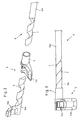
- FIG. 1 shows a side view of a medical instrument 1, the power transmission mechanism of which can be used in a variety of ways, such as stamping, scissors, needle holders, drum instruments and the like.
- the medical instrument 1 essentially consists of a hollow shaft 2, on the proximal end of which a handle 3 a, consisting of a rigid grip part 3 a and a handle part 3 b pivotable about a pivot axis 4, is disposed.
- a tool 5 is arranged, which consists in the illustrated embodiment (Fig. 2 and 3) of a pivotable jaw part 5a and a rigidly connected to the shaft 2 jaw part 5b.
- FIGS. 2 to 6 show that the jaw parts 5a, 5b of the tool 5 are bent laterally with respect to the longitudinal axis of the shaft 2.
- the jaws 5a, 5b are each aligned at right angles to the longitudinal axis of the instrument shaft. Other angular positions between 0 ° and 90 ° and beyond, however, are also practicable.
- the pivotable jaw part 5a is mounted at the distal end of a pull / push rod 6 which is mounted in the hollow shaft 2 on the proximal side with the pivotable grip part 3b of the handle 3 by the pivoting of the handle part 3b, the pivotable jaw part 5a can be transferred from a closed position to an open position or vice versa.
- the pull / push rods 6 are each constructed in several parts, consisting of individual sections 6a.
- the mutually facing ends of the sections 6a are formed as a helical so that in each case two helical guideways 7 are screwed into one another, as shown in the figures Fig. 3 and 5 can be seen.
- the proximal portion 6a of the pull / push rod 6 can be additionally extended and / or alternatively extended to the illustrated embodiment, depending on the respective handle 3 to be used on the proximal side and shaped
- the distal end of the hollow shaft 2 is closed in order to prevent axial displacement of the section 6a of the pull / push rod 6 provided with the pivotable jaw part 5a.
- this axial displacement of the proximal section 6a of the pull / push rod 6 causes the helical guideways 7 of the two sections 6a to be screwed into one another or one another
- the proximal portion 6a of the pull / push rod 6 is mounted non-rotatably on the pivotable handle part 3b of the handle 3
- the interlocking or disassembling of the helical guideways 7 of the two sections 6a causes the distal, with the pivotable jaw part 5a provided portion 6a of the pull / push rod 6 a rotational movement about his Performs longitudinal axis, whereby the pivotable jaw part 5a is adjustable between an open and a closed position.
- FIGS. 2 and 4 differ from one another in that the two helical guideways 7 of the sections 6a of the pull / push rod 6 have one and a half threads in the embodiment according to FIGS. 2 and 3, while in the embodiment according to FIG 4 and 5, the guideways 7 of each section 6a have only half a thread.
- the helical guideways 7 can be designed as a helical groove in the lateral surface of the pull / push rod 6, as shown in FIG is shown, or form as a helical groove on the inside of the hollow shaft 2, wherein for generating the rotational movement on the inside of the hollow shaft 2 or on the lateral surface of the pull / push rod 6 rigid abutment 8 are arranged, with the respective helical grooves interact.
- the abutment 8 is formed as arranged on the inside of the hollow shaft 2 and engaging in the helical groove bolts.
- the pull / push rod 6 is freely rotatable about its longitudinal axis on the pivotable handle part 3b of the handle 3, so that the pull / push rod 6 when starting against the respective abutment due to the operation of the pivotable handle part 3b can rotate about its longitudinal axis.
- a medical instrument as described above is distinguished by the fact that, with a simple structural design and simple handling, a uniform and reliable conversion of the axial movement transmitted by the pivotable grip part 3b to the pull / push rod 6 into a rotational movement of the pivotable jaw part 5a is largely free of play Power transmission guaranteed.
Landscapes
- Health & Medical Sciences (AREA)
- Surgery (AREA)
- Life Sciences & Earth Sciences (AREA)
- Biomedical Technology (AREA)
- Medical Informatics (AREA)
- Veterinary Medicine (AREA)
- Public Health (AREA)
- Engineering & Computer Science (AREA)
- General Health & Medical Sciences (AREA)
- Heart & Thoracic Surgery (AREA)
- Nuclear Medicine, Radiotherapy & Molecular Imaging (AREA)
- Molecular Biology (AREA)
- Animal Behavior & Ethology (AREA)
- Dentistry (AREA)
- Oral & Maxillofacial Surgery (AREA)
- Orthopedic Medicine & Surgery (AREA)
- Ophthalmology & Optometry (AREA)
- Surgical Instruments (AREA)
Applications Claiming Priority (1)
| Application Number | Priority Date | Filing Date | Title |
|---|---|---|---|
| DE102005021234A DE102005021234A1 (de) | 2005-05-09 | 2005-05-09 | Medizinisches Instrument |
Publications (2)
| Publication Number | Publication Date |
|---|---|
| EP1721577A1 true EP1721577A1 (fr) | 2006-11-15 |
| EP1721577B1 EP1721577B1 (fr) | 2008-04-02 |
Family
ID=36832258
Family Applications (1)
| Application Number | Title | Priority Date | Filing Date |
|---|---|---|---|
| EP06008584A Expired - Lifetime EP1721577B1 (fr) | 2005-05-09 | 2006-04-26 | Instrument endoscopique |
Country Status (3)
| Country | Link |
|---|---|
| US (1) | US8128651B2 (fr) |
| EP (1) | EP1721577B1 (fr) |
| DE (2) | DE102005021234A1 (fr) |
Cited By (2)
| Publication number | Priority date | Publication date | Assignee | Title |
|---|---|---|---|---|
| WO2010099930A1 (fr) * | 2009-03-04 | 2010-09-10 | Karl Storz Gmbh & Co. Kg | Appareil médical |
| EP2769682A1 (fr) * | 2013-02-20 | 2014-08-27 | Karl Storz GmbH & Co. KG | Instrument endoscopique et tige pour un instrument endoscopique |
Families Citing this family (7)
| Publication number | Priority date | Publication date | Assignee | Title |
|---|---|---|---|---|
| US20070123933A1 (en) * | 2005-11-29 | 2007-05-31 | Ethicon Endo-Surgery, Inc. | Manually operable equipment |
| USD698920S1 (en) * | 2011-12-29 | 2014-02-04 | Karl Storz Gmbh & Co. Kg | Medical instrument handle with connector |
| DE102012007651A1 (de) * | 2012-04-18 | 2013-10-24 | Karl Storz Gmbh & Co. Kg | Kupplung zwischen zwei Teilen eines medizinischen Instruments |
| USD804029S1 (en) * | 2015-01-16 | 2017-11-28 | Karl Storz Gmbh & Co. Kg | Scissor |
| GB2553259B (en) | 2016-05-17 | 2021-07-14 | Creo Medical Ltd | Control device for a surgical instrument |
| CN114513981B (zh) * | 2019-08-14 | 2025-09-09 | 凌赛解决方案有限公司 | 用于血管采集的装置 |
| DE102021208391A1 (de) * | 2021-08-03 | 2023-02-09 | Aesculap Ag | Medizinisches Instrument |
Citations (4)
| Publication number | Priority date | Publication date | Assignee | Title |
|---|---|---|---|---|
| US4258716A (en) * | 1978-02-06 | 1981-03-31 | The University Of Melbourne | Microsurgical instruments |
| DE8302716U1 (de) * | 1983-05-26 | Straub, Reinhold, 7230 Schramberg | Mikrochirurgisches Instrument. | |
| WO1991002493A1 (fr) * | 1989-08-16 | 1991-03-07 | Raychem Corporation | Dispositif pour saisir ou pour couper un objet |
| EP0677275A2 (fr) * | 1994-03-17 | 1995-10-18 | Terumo Kabushiki Kaisha | Instrument chirurgical |
Family Cites Families (8)
| Publication number | Priority date | Publication date | Assignee | Title |
|---|---|---|---|---|
| US2894324A (en) * | 1958-08-11 | 1959-07-14 | Carl L Hardin | Wire cutter |
| US3687373A (en) * | 1970-12-08 | 1972-08-29 | Wade & Co R M | Reversing water motor |
| US4499899A (en) * | 1983-01-21 | 1985-02-19 | Brimfield Precision, Inc. | Fiber-optic illuminated microsurgical scissors |
| DE3303349A1 (de) * | 1983-02-02 | 1984-08-02 | Reinhold 7230 Schramberg Straub | Chirurgisches instrument zum schneiden von gewebe insb. knorpel |
| US5052660A (en) * | 1990-09-17 | 1991-10-01 | William Bergman | Electrical wire threading apparatus |
| US5707379A (en) * | 1995-10-20 | 1998-01-13 | Coral Medical | Method and apparatus for intracorporeal suturing |
| DE60134236D1 (de) * | 2000-07-20 | 2008-07-10 | Kinetic Surgical Llc | Manuell gesteuertes chirurgisches werkzeug mit gelenk |
| DE10327655A1 (de) * | 2003-06-20 | 2005-01-27 | Karl Storz Gmbh & Co. Kg | Medizinisches Instrument |
-
2005
- 2005-05-09 DE DE102005021234A patent/DE102005021234A1/de not_active Withdrawn
-
2006
- 2006-04-26 DE DE502006000550T patent/DE502006000550D1/de not_active Expired - Lifetime
- 2006-04-26 EP EP06008584A patent/EP1721577B1/fr not_active Expired - Lifetime
- 2006-05-09 US US11/430,583 patent/US8128651B2/en not_active Expired - Fee Related
Patent Citations (4)
| Publication number | Priority date | Publication date | Assignee | Title |
|---|---|---|---|---|
| DE8302716U1 (de) * | 1983-05-26 | Straub, Reinhold, 7230 Schramberg | Mikrochirurgisches Instrument. | |
| US4258716A (en) * | 1978-02-06 | 1981-03-31 | The University Of Melbourne | Microsurgical instruments |
| WO1991002493A1 (fr) * | 1989-08-16 | 1991-03-07 | Raychem Corporation | Dispositif pour saisir ou pour couper un objet |
| EP0677275A2 (fr) * | 1994-03-17 | 1995-10-18 | Terumo Kabushiki Kaisha | Instrument chirurgical |
Cited By (3)
| Publication number | Priority date | Publication date | Assignee | Title |
|---|---|---|---|---|
| WO2010099930A1 (fr) * | 2009-03-04 | 2010-09-10 | Karl Storz Gmbh & Co. Kg | Appareil médical |
| EP2769682A1 (fr) * | 2013-02-20 | 2014-08-27 | Karl Storz GmbH & Co. KG | Instrument endoscopique et tige pour un instrument endoscopique |
| US10004523B2 (en) | 2013-02-20 | 2018-06-26 | Karl Storz Se & Co. Kg | Endoscopic instrument, and shaft for an endoscopic instrument |
Also Published As
| Publication number | Publication date |
|---|---|
| US20060282117A1 (en) | 2006-12-14 |
| DE102005021234A1 (de) | 2006-11-16 |
| EP1721577B1 (fr) | 2008-04-02 |
| DE502006000550D1 (de) | 2008-05-15 |
| US8128651B2 (en) | 2012-03-06 |
Similar Documents
| Publication | Publication Date | Title |
|---|---|---|
| EP1464289B1 (fr) | Instrument chirurgical, dans lequel les mouvements de la tête et de l'outil sont découplés | |
| EP2874548B1 (fr) | Instrument endoscopique | |
| EP1464290B1 (fr) | Instrument chirurgical | |
| EP1235522B1 (fr) | Instrument chirurgical pour intervention minimale invasive | |
| DE10314828B3 (de) | Chirurgisches Instrument | |
| EP0767625B1 (fr) | Instrument chirurgical | |
| EP1488749B1 (fr) | Dispositif médical | |
| EP1279371B1 (fr) | Instrument chirurgical | |
| EP2601895B1 (fr) | Instrument médical | |
| DE102015015655A1 (de) | Medizinisches Instrument | |
| EP1289434A1 (fr) | Instrument medical | |
| EP1721577B1 (fr) | Instrument endoscopique | |
| DE10060769C2 (de) | Medizinisches Instrument | |
| DE102014117393A1 (de) | Dreh- und abwinkelbares medizinisches Instrument | |
| DE19713067C2 (de) | Arthroskopie-Instrument | |
| EP1365691B1 (fr) | Instrument medical | |
| DE10036108A1 (de) | Chirurgisches Instrument für minimal invasive Eingriffe | |
| EP2403418B1 (fr) | Instrument médical | |
| DE102015215469A1 (de) | Instrument, insbesondere medizinisch-endoskopisches Instrument | |
| DE4319968C1 (de) | Chirugisches Rohrschaftinstrument | |
| DE19703600A1 (de) | Medizinisches Instrument für endoskopische Eingriffe | |
| DE8903111U1 (de) | Chirurgische Zange zur Gewebeentnahme |
Legal Events
| Date | Code | Title | Description |
|---|---|---|---|
| PUAI | Public reference made under article 153(3) epc to a published international application that has entered the european phase |
Free format text: ORIGINAL CODE: 0009012 |
|
| AK | Designated contracting states |
Kind code of ref document: A1 Designated state(s): AT BE BG CH CY CZ DE DK EE ES FI FR GB GR HU IE IS IT LI LT LU LV MC NL PL PT RO SE SI SK TR |
|
| AX | Request for extension of the european patent |
Extension state: AL BA HR MK YU |
|
| 17P | Request for examination filed |
Effective date: 20070509 |
|
| AKX | Designation fees paid |
Designated state(s): DE FR GB IT |
|
| GRAP | Despatch of communication of intention to grant a patent |
Free format text: ORIGINAL CODE: EPIDOSNIGR1 |
|
| GRAS | Grant fee paid |
Free format text: ORIGINAL CODE: EPIDOSNIGR3 |
|
| GRAA | (expected) grant |
Free format text: ORIGINAL CODE: 0009210 |
|
| AK | Designated contracting states |
Kind code of ref document: B1 Designated state(s): DE FR GB IT |
|
| REG | Reference to a national code |
Ref country code: GB Ref legal event code: FG4D Free format text: NOT ENGLISH |
|
| REF | Corresponds to: |
Ref document number: 502006000550 Country of ref document: DE Date of ref document: 20080515 Kind code of ref document: P |
|
| ET | Fr: translation filed | ||
| PLBE | No opposition filed within time limit |
Free format text: ORIGINAL CODE: 0009261 |
|
| STAA | Information on the status of an ep patent application or granted ep patent |
Free format text: STATUS: NO OPPOSITION FILED WITHIN TIME LIMIT |
|
| 26N | No opposition filed |
Effective date: 20090106 |
|
| PGFP | Annual fee paid to national office [announced via postgrant information from national office to epo] |
Ref country code: GB Payment date: 20100329 Year of fee payment: 5 |
|
| PGFP | Annual fee paid to national office [announced via postgrant information from national office to epo] |
Ref country code: FR Payment date: 20100506 Year of fee payment: 5 |
|
| PGFP | Annual fee paid to national office [announced via postgrant information from national office to epo] |
Ref country code: DE Payment date: 20100407 Year of fee payment: 5 Ref country code: IT Payment date: 20100407 Year of fee payment: 5 |
|
| GBPC | Gb: european patent ceased through non-payment of renewal fee |
Effective date: 20110426 |
|
| REG | Reference to a national code |
Ref country code: FR Ref legal event code: ST Effective date: 20111230 |
|
| PG25 | Lapsed in a contracting state [announced via postgrant information from national office to epo] |
Ref country code: FR Free format text: LAPSE BECAUSE OF NON-PAYMENT OF DUE FEES Effective date: 20110502 Ref country code: DE Free format text: LAPSE BECAUSE OF NON-PAYMENT OF DUE FEES Effective date: 20111101 |
|
| REG | Reference to a national code |
Ref country code: DE Ref legal event code: R119 Ref document number: 502006000550 Country of ref document: DE Effective date: 20111101 |
|
| PG25 | Lapsed in a contracting state [announced via postgrant information from national office to epo] |
Ref country code: GB Free format text: LAPSE BECAUSE OF NON-PAYMENT OF DUE FEES Effective date: 20110426 Ref country code: IT Free format text: LAPSE BECAUSE OF NON-PAYMENT OF DUE FEES Effective date: 20110426 |