EP1721835A2 - Verschlusskappe und damit versehener Behälter. - Google Patents
Verschlusskappe und damit versehener Behälter. Download PDFInfo
- Publication number
- EP1721835A2 EP1721835A2 EP06300443A EP06300443A EP1721835A2 EP 1721835 A2 EP1721835 A2 EP 1721835A2 EP 06300443 A EP06300443 A EP 06300443A EP 06300443 A EP06300443 A EP 06300443A EP 1721835 A2 EP1721835 A2 EP 1721835A2
- Authority
- EP
- European Patent Office
- Prior art keywords
- opening control
- container
- control element
- lid
- base portion
- Prior art date
- Legal status (The legal status is an assumption and is not a legal conclusion. Google has not performed a legal analysis and makes no representation as to the accuracy of the status listed.)
- Granted
Links
Images




Classifications
-
- B—PERFORMING OPERATIONS; TRANSPORTING
- B65—CONVEYING; PACKING; STORING; HANDLING THIN OR FILAMENTARY MATERIAL
- B65D—CONTAINERS FOR STORAGE OR TRANSPORT OF ARTICLES OR MATERIALS, e.g. BAGS, BARRELS, BOTTLES, BOXES, CANS, CARTONS, CRATES, DRUMS, JARS, TANKS, HOPPERS, FORWARDING CONTAINERS; ACCESSORIES, CLOSURES, OR FITTINGS THEREFOR; PACKAGING ELEMENTS; PACKAGES
- B65D47/00—Closures with filling and discharging, or with discharging, devices
- B65D47/04—Closures with discharging devices other than pumps
- B65D47/06—Closures with discharging devices other than pumps with pouring spouts or tubes; with discharge nozzles or passages
- B65D47/08—Closures with discharging devices other than pumps with pouring spouts or tubes; with discharge nozzles or passages having articulated or hinged closures
- B65D47/0804—Closures with discharging devices other than pumps with pouring spouts or tubes; with discharge nozzles or passages having articulated or hinged closures integrally formed with the base element provided with the spout or discharge passage
- B65D47/0809—Closures with discharging devices other than pumps with pouring spouts or tubes; with discharge nozzles or passages having articulated or hinged closures integrally formed with the base element provided with the spout or discharge passage and elastically biased towards both the open and the closed positions
-
- B—PERFORMING OPERATIONS; TRANSPORTING
- B65—CONVEYING; PACKING; STORING; HANDLING THIN OR FILAMENTARY MATERIAL
- B65D—CONTAINERS FOR STORAGE OR TRANSPORT OF ARTICLES OR MATERIALS, e.g. BAGS, BARRELS, BOTTLES, BOXES, CANS, CARTONS, CRATES, DRUMS, JARS, TANKS, HOPPERS, FORWARDING CONTAINERS; ACCESSORIES, CLOSURES, OR FITTINGS THEREFOR; PACKAGING ELEMENTS; PACKAGES
- B65D2251/00—Details relating to container closures
- B65D2251/10—Details of hinged closures
- B65D2251/1016—Means for locking the closure in closed position
- B65D2251/1041—The closure having a part penetrating in the dispensing aperture and retained by snapping over integral beads or projections
Definitions
- the present invention relates to containers equipped with closure caps having a base portion provided with at least one dispensing orifice and a lid pivoting relative to the base portion, the capsule having a cover opening control member.
- Japanese JP 1-66355 discloses a closure cap having a base portion comprising an internally threaded skirt, to be screwed onto the neck of the container, surrounded by an outer covering skirt.
- a cover is hinged to this base portion by means of a hinge having a tongue forming a spring, to assist the opening movement of the lid.
- An opening control member is slidable on the base portion to act on the lid and hinge.
- Such a capsule is not entirely satisfactory, particularly from an aesthetic point of view, because at rest, when the lid is closed, the opening control element protrudes forward a significant distance.
- the patent application European EP 0 699 591 discloses a capsule having an outer trim skirt which is interrupted on the side opposite the hinge to receive the opening control member, which comprises a pusher hinged to the base portion and a pusher member slidable in a recess of the basic part.
- the thrust member has ramps for cooperating with reliefs of the cover to cause the lifting thereof and an end for acting on the spring tab of the hinge.
- the thrust member comprises an oblong cut in which is engaged a dispensing nozzle. Such cutting is likely to promote the accumulation of dirt, as well as the recess in which slides the thrust member.
- the patent US 6,834,769 discloses a container having a closure cap in which the opening control member slides within the base portion.
- the opening control member has a projecting portion, on the side opposite the hinge, on which the user must press to open the lid.
- the opening control element shall be in the form of an insert, which has an impact on the manufacturing cost.
- the support surface offered to the user is relatively small, which can affect comfort of use.
- closure cap that can be easily made by plastic molding, which is aesthetically pleasing, easy to use and reduces the risk of accumulation of dirt.
- the object of the invention is, according to one of its aspects, a closure cap comprising a base part provided with at least one dispensing orifice, to be fixed on a container body, a pivoting lid and a control element. opening of the lid, wherein the opening control element comprises a skirt surrounding at least a portion of the base portion and connected thereto by at least one elastically deformable connecting element.
- the skirt of the opening control member may act as a pusher to allow the user to control the opening while concealing the upper body of the container on which the capsule is mounted.
- the skirt can provide a relatively large support surface to the user, which increases comfort in use.
- the one or more elastically deformable connecting elements can act in an exemplary implementation of the invention as an elastic return means for returning the skirt to its initial position after the actuation by the user.
- the capsule can be made in such a way as to reduce the risk of accumulation of dirt, thanks for example to the absence of cutouts surrounding the dispensing orifice externally and to the possibility of absence of an external guide recess of the opening control element similar to those of the prior art.
- the capsule is molded entirely in one piece, thanks to the presence of or elastically deformable connecting elements.
- the deformable connecting element or elements allow the different parts of the capsule to be arranged in a configuration that facilitates the molding and can then deform when the capsule is mounted on the body of the container in order to take their final configuration.
- the opening control element is not monolithic with the base part.
- the opening control element and the base part can be made separately and then assembled.
- the base portion and the opening control element may be made in the same mold so as to allow their assembly during demolding of the capsule.
- the capsule comprises two elastically deformable connecting elements connecting the pusher skirt to the base portion.
- the elastically deformable connecting elements may for example be connected at one end to the skirt of the opening control element and at the other end to a portion of the base portion for mounting it on a collar. of the container.
- the deformable connecting elements are for example each in the form of an arm having a non-rectilinear shape, particularly corrugated.
- the elastically deformable connecting elements come into contact with the base part while being able to slide in contact with it when the user presses on the opening control element.
- the connecting members may each be connected at two opposite ends to a portion of the opening control member.
- the connecting members may comprise two curved portions having concavities directed toward each other, these curved portions being configured to engage the base portion when the opening control member is at rest.
- the connecting elements can deform elastically in contact with the base portion and thus ensure the return of the control element to its initial position when the user releases it.
- the skirt of the opening control element may have any shape, preferably adapted to that of the upper part of the body of the container and for example a circular or oblong cross section.
- the skirt may have on the face supporting the user an extension extending downwards, engaged in a recess of corresponding shape of the body of the container.
- the elastically deformable connecting elements can be connected to the skirt of the opening control element at locations located substantially opposite each other in a plane parallel to the axis of rotation of the lid and can also be connected to the base portion at substantially opposite locations in this plane.
- the opening control element may comprise at least one relief arranged to cooperate with the body of the container so that the body of the container at least partially guides the displacement of the opening control element when it is operated by the user.
- the upper wall of the body of the container may in particular have a shouldered shape defining at least one guide surface and better two opposite guide surfaces, along which the opening control element can move.
- the two aforementioned guide surfaces can be made on either side of the neck while being oriented in a direction substantially perpendicular to this large one. axis.
- the neck of the container may comprise at least one angular positioning relief of the base portion of the capsule relative to the body of the container.
- This relief may for example be in the form of a rib extending at least partially along the neck, for example substantially symmetrically relative to a median plane perpendicular to the axis of rotation of the lid.
- the base portion of the capsule may comprise for example at least one notch in which the aforementioned rib can engage during assembly of the base portion on the body of the container.
- the base portion may comprise, on its radially inner surface, at least one relief intended to snap on a corresponding relief made on the neck, near its base, for example.
- the base portion may include an annular sealing lip for application to the radially inner surface of the neck.
- the skirt of the opening control element can be extended, especially in the upper part, by a return to the inside.
- the connecting elements are connected at their ends to this return and extend for example substantially in the same plane.
- the base portion comprises, in an exemplary implementation of the invention, a plate that covers at least partially this return when the closure cap is in place on the container.
- the plate and the return can be molded apart from each other, for example by a distance greater than or equal to 4 mm, this can make it possible to improve the mechanical strength of the mold, even to 5 mm, thanks to the presence of the deformable connecting element or elements and this or these latter then allow an axial movement of the plate relative to the control element of the mold. opening when fastened to the body of the container.
- the plate may have only a clearance of the order of 0.2 mm to 0.5 mm with the return, so as to maintain the skirt axially in place while allowing it to move towards the hinge when the user pushes on it.
- the elastically deformable connecting element or elements are for example in the form of arms having a corrugated shape, as indicated above, and these arms can extend for example in a plane substantially perpendicular to the axis of the portion of the base portion for mounting on the container.
- these arms can deform and extend obliquely to the body of the container once the base portion attached to the neck.
- the deformable connecting elements are rectilinear.
- the clearance between the plate and the return during molding is lower, being chosen for example according to the modulus of elasticity of the material in which the connecting elements are molded.
- the connecting elements are molded so as to be able to be snapped onto the base portion during demolding of the capsule.
- the lid may be molded with or attached to the base portion.
- the lid can be molded with the base part or attached to the base part and fixed on it for example by snapping.
- the lid can be molded in one piece with the base part.
- the hinge connecting the lid to the base portion advantageously comprises at least one spring tongue, which can assist the opening movement of the lid.
- This tongue can be bent, and go through a state of maximum stress when the lid is in an intermediate position between the closed position and the open position.
- the opening control element is advantageously arranged to act on the spring tongue, when actuated by the user, by pushing this tongue to the trigger point of the spring effect.
- the opening control member may comprise, on the hinge side, a tab for pressing the spring tongue.
- This tab may have a square shape so as to press the spring tongue at a location elevated relative to the axis of rotation of the lid.
- the opening control element is also advantageously arranged to act directly on the lid when actuated by the user, for example to facilitate the disengagement of a closure pin carried by the cover, the orifice distribution of the basic part.
- the opening control element is thus arranged to act on a relief carried by the cover in a region thereof located substantially opposite the hinge.
- the cover may for example have a tooth on its underside, near its edge opposite the hinge, and the base portion of the tray may include an opening for this tooth to cooperate with the opening control element. when the user presses on it to move it towards the hinge.
- the aforementioned return of the opening control element may for example comprise a notch in which engages the tooth of the cover and the bottom of this notch may come to bear on an inclined face of the tooth at the beginning of the displacement of the opening control element, so as to cause a beginning of pivoting of the lid.
- the cover may be arranged to extend, in the closed position and when the opening control member is at rest, away from the opening control member, the side opposite the hinge, or the opposite protrude forward of the opening control element.
- the opening control element may be configured to be movable from a non-zero stroke before acting on the lid. This may allow the edge of the lid to protrude forward of the opening control member before it has begun to act on the lid.
- the dispensing orifice may be defined by an annular surface extended inferiorly by at least one elastically deformable tab, arranged to snap onto a sealing pin carried by the cover.
- the annular surface may for example be extended by a plurality of tabs arranged to snap onto the sealing pin elsewhere than the opposite side to the face of the control element on which the user presses to cause the lid to open. This can help not to hinder the opening of the lid.
- the invention further relates to a container having a body and a closure cap as defined above, fixed on the body.
- the body of the container may be arranged to have a stepped top wall, so as to guide the movement of the opening control member.
- the invention further relates, in another of its aspects, a container having a closure cap and a body on which is fixed the closure cap, the closure cap having a base portion attached to the body and a lid pivotable relative to the base portion, and an opening control member movable relative to the base portion to act on the lid and cause it to open.
- the body of the container is advantageously arranged to guide the opening control element in displacement.
- the base portion of the capsule may comprise a plate and the opening control element may be retained axially on the container body by means of this plate, with nevertheless a possibility of sliding to act on the lid. The realization of the closure cap can then be facilitated.
- the container may be filled, before or after mounting the closure cap, a fluid or powder, for example a cosmetic product, including care.
- the first piece is for example the base portion of the closure cap defined above and the second piece the opening control member.
- the first piece may be molded in a first material and the second piece in a second material, different from the first, for example of different color.
- the base part can be molded in one piece with the cover.
- At least one drawer may be provided in the mold, at least partially delimiting the cavities used for molding the two parts. This drawer can be moved to allow the extraction pusher to act.
- the aforementioned surface may be extended by one or more elastically deformable tabs arranged to snap into an annular groove formed on the closure pin.
- This surface may be devoid of extension cooperating with the sealing pin on the opposite side to the face of the opening control element on which the user presses to open the lid.
- the opening of the lid is not embarrassed by a pinch hook on the base portion that would tend to increase while the user would support.
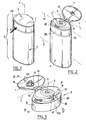
- the container shown in FIGS. 1 and 2, comprises a body 2 on which is fixed a closure cap 3.
- the container 1 has an elongate shape along a longitudinal axis X and the body 2 has an oblong shape in cross section, elongated along a major axis Z.
- the closure cap 3 which has been shown separately in FIGS. 3 to 6, comprises a base portion 5 provided with a dispensing orifice 6, a cover 7 articulated on the base part 5 about an axis Y substantially parallel to the major axis Z and an opening control member 8 movable relative to the base portion in a direction generally perpendicular to the hinge axis Y.
- the lid 7 is connected to the base portion by a film hinge 10 having two parts disposed on either side of a tongue 12 forming a spring, sometimes called knee, passing through a state of maximum stress in an intermediate position between the closed position and the open position, so as to assist the opening movement of the cover 7 and ensure that the latter, once opened, maintains its position.
- a film hinge 10 having two parts disposed on either side of a tongue 12 forming a spring, sometimes called knee, passing through a state of maximum stress in an intermediate position between the closed position and the open position, so as to assist the opening movement of the cover 7 and ensure that the latter, once opened, maintains its position.
- the lid 7 comprises a pin 14 for closing the orifice 6, provided with at least one relief 15 configured to snap onto the lower edge 16 of the orifice 6 when the lid 7 is completely closed.
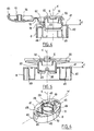
- the base portion 5 comprises on the one hand an elongate plate 20 along a major axis W and on the upper face of which opens the orifice 6 and on the other hand a portion 22, extending under the plate 20, used for the fixing on a neck 24 of the container, which is apparent in FIG.
- the portion 22 is in the form of a tubular mounting skirt of axis K, provided inferiorly on its radially inner face with an annular bead 23 intended to snap onto a corresponding bead 26 of the neck 24.
- the portion 22 further comprises in the example considered two notches 28 arranged to receive ribs 30 of the neck 24, so that the major axis W of the plate 20 is substantially parallel to the major axis Z of the body 2.
- An annular sealing lip 33 intended to be applied on the radially inner surface of the neck 24 is connected to the lower face of the plate 20.
- the opening control element 8 comprises a tubular skirt 40 which extends all around the neck 24, and which has, in the example in question, in cross section, a substantially homothetic shape of that of the body 2, as can be seen in FIG. see it in Figures 1 and 2.
- the skirt 40 is extended in the upper part by a return 41 directed inwards.
- This return 41 is partially covered by the plate 20 when the capsule 3 is fixed on the neck of the container 2, as can be seen in FIG.
- the skirt 40 of the opening control element 8 is connected to the portion 22 of the base portion 5 via the example in the example of two arms 45. elastically deformable, each having substantially the shape of a sinusoidal period.
- the arms 45 join the skirt 40 and the portion 22 at locations substantially in a plane containing the major axis W of the capsule 3. When the latter is molded, the arms 45 extend substantially in the extension of the return 41, perpendicularly to the axis K of the portion 22.
- the distance d between the plate 20 and the return 41 is then for example of the order of 5 mm, which facilitates the realization of the capsule by molding a thermoplastic material, for example a polyolefin.
- the arms 45 can deform obliquely downward to allow the portion 22 to snap on the neck 24, as shown in Figure 10.
- the opening control element 8 comprises uprights 49 extending substantially parallel to the axis K on either side of the portion 22 and intended to cooperate with guide surfaces 50 formed by shoulders of the wall upper transverse 52 of the body 2, which is connected below the neck 24. These guide surfaces 50 are oriented substantially perpendicular to the major axis Z of the container. The cooperation of the uprights 49 and the surfaces 50, by supporting the uprights 49 on the latter, ensures the translational guidance of the skirt 40 in a direction perpendicular to the major axis W.
- the plate 20 When thrust is exerted on the cover 7 in the direction of the body 2, the plate 20 approaches the return 41 and the portion 22 is fixed by snapping on the neck 24, as can be seen in Figures 10 and 11.
- the final clearance between the plate 20 and the return 41 is 0.2 to 0.5 mm, for example.
- the opening control element 8 comprises, on the opposite side to the surface 100 on which the user presses to control the opening, a tab 60 intended to act on the spring tongue 12, in order to push the latter up to at the trigger point causing the lid to open.
- the opening control element 8 is also arranged to act on a relief 63 of the cover 7 in order to cause the lid to begin to rise and in particular to disengage the closure pin 14, as illustrated in FIG. 12.
- the relief 63 is in the form of a tooth made near the edge of the lid which is opposite the hinge 10.
- the plate 20 comprises, on its edge opposite the hinge 10, an opening 66 for the passage of the tooth 63.
- the return 41 has a notch 70 whose bottom 71 can bear against an inclined face of the tooth 63, so as to cause the lifting of the lid during the displacement of the skirt 40, as can be seen in FIG. 12.
- the tab 60 has, in the example illustrated, a square shape and its free end 72 is located, when the closure cap 3 is in place on the container, at a level slightly greater than that of the axis of rotation Y of the lid.
- bracket-shaped tab 60 bears at its end 72 on the spring tab 12 until the latter passes through its state of maximum stress, the end of the opening movement of the cover being ensured by the return of the energy accumulated in the spring tongue 12.
- the arms 45 When moving the opening control member 8 to open the lid, the arms 45 have elastically deformed. Once the user stops pressing the skirt 40 and releases it, the arms 45 can bring it substantially back to its initial position, as illustrated in FIG. 14.
- FIGS. 15 and 16 show a container 1 comprising a closure cap 3 and a body 2 which is in the form of a flexible tube.
- the body 2 has in the upper part a substantially circular cross section and the skirt 40 also has, in cross section, a substantially circular shape.
- This example differs from that of FIGS. 1 to 14 in particular by the way in which the opening control element 8 is connected to the base part 5.
- each arm 110 has a curved portion 114 adapted to substantially match the shape of the portion 22 of the base portion for its attachment to the neck 24 of the container, when the user does not exert any pressure on the control element.
- the portion 22 comprises, in the example considered, a mounting skirt arranged to snap on the neck 24.
- the curved portions 114 are connected to the edge 111 by portions 120 parallel to each other and both perpendicular to the major axis W.
- the curved portions 114 are connected to the edge 112 by rectilinear portions 122 which diverge slightly towards the edge 112.
- each elbow 126 formed at the junction of the curved and rectilinear portions 114 remains, at the end of the displacement of the skirt 40, on the same side of the half-plane containing the axis of the dispensing orifice 6 and the major axis W, so that when the user releases the opening control element 8, the arm 110 tend to bring the latter back to its initial position, represented in FIG.
- the body 2 of the container may comprise a recess 140, as shown in Figure 17, and the skirt 40 may have the side where the user supports an extension 141 conforming to the shape of the recess 140, as shown in Figures 18 and 19.
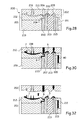
- closure cap 3 can be manufactured in the same mold, as will now be described with reference to Figures 28 to 39.
- the mold 200 used has a first portion 201 and a second portion 202 which define a first cavity 203 for molding the base portion and the lid and a second cavity 204 which can be without communication with the cavity 203, for the molding of the opening control element 8.
- the material is injected into the cavities 203 and 204, in the example under consideration, by respective injection channels 205 and 206.
- the cavity 203 is defined between on the one hand parts 210 and 218 belonging to the second part 202 of the mold, and secondly side drawers 211 and 212 and parts 213 and 215 belonging to the first part 201 of the mold.
- the cavity 204 is defined between, on the one hand, the part 210 and, on the other hand, the part 215, the drawers 211 and 212, a part 220 and an extraction pusher 219.
- thermoplastic material may be the same thermoplastic material with different colors and / or different chemical materials.
- the injection can take place simultaneously in the cavities 204 and 203, as illustrated in FIG. 30.
- the second part of the mold 202 is moved away from the first, as illustrated in FIGS. 32 and 33.
- the drawers 211 and 212 can be spaced apart as illustrated in FIG.
- the pusher 219 can be raised to cause the arms 110 to snap behind the teeth 148 of the portion 22 of the base portion 5.
- the complete extraction of the closure cap can then take place by extending the upward stroke of the pusher 219, as illustrated in FIGS. 38 and 39.
- the skirt 40 of the opening control element 8 can be made, as illustrated in FIG. 40, so as to its driving stroke is carried out before the tooth 63 comes to bear against the edge of the return 41, over a distance M greater than the distance m from which the skirt 40 may project forward with respect to at the free edge 170 of the lid 7.
- edge 170 can oppose accidental depression of the skirt 40 during transport of the container for example, coming directly above the skirt 40 before it bears by the return 41 against the tooth 63, as shown in Figures 41 and 42.
- the dispensing orifice 6 can be defined by an annular surface 180, for example cylindrical, extended below by tabs 181 which may comprise teeth 182 intended for snap into a corresponding groove 183 of the sealing pin 14, as shown in Figures 42 to 44.
- the surface 180 may not be extended, on the hinge side of the lid, by a tab 181 provided with a tooth 182, so as to facilitate the opening of the lid.
- sealing pin and the dispensing orifice may be made in accordance with the teaching of the patent application. US 2005/0173366 .
- the capsule can be fixed on the neck otherwise than by snapping, for example by clamping.
- the cooperation of the body of the container and the opening control member can be performed even differently, other reliefs that the shoulders being for example made on the upper transverse wall of the container.
Landscapes
- Engineering & Computer Science (AREA)
- Mechanical Engineering (AREA)
- Closures For Containers (AREA)
- Containers And Packaging Bodies Having A Special Means To Remove Contents (AREA)
- Medical Preparation Storing Or Oral Administration Devices (AREA)
- Finger-Pressure Massage (AREA)
Priority Applications (1)
| Application Number | Priority Date | Filing Date | Title |
|---|---|---|---|
| EP07000781A EP1770022B1 (de) | 2005-05-09 | 2006-05-05 | Verschlusskappe |
Applications Claiming Priority (1)
| Application Number | Priority Date | Filing Date | Title |
|---|---|---|---|
| FR0504619A FR2885355B1 (fr) | 2005-05-09 | 2005-05-09 | Capsule de fermeture et recipient ainsi equipe |
Related Child Applications (2)
| Application Number | Title | Priority Date | Filing Date |
|---|---|---|---|
| EP07000781A Division EP1770022B1 (de) | 2005-05-09 | 2006-05-05 | Verschlusskappe |
| EP07000781.0 Division-Into | 2007-01-16 |
Publications (3)
| Publication Number | Publication Date |
|---|---|
| EP1721835A2 true EP1721835A2 (de) | 2006-11-15 |
| EP1721835A3 EP1721835A3 (de) | 2007-01-03 |
| EP1721835B1 EP1721835B1 (de) | 2010-05-26 |
Family
ID=35560654
Family Applications (2)
| Application Number | Title | Priority Date | Filing Date |
|---|---|---|---|
| EP06300443A Expired - Lifetime EP1721835B1 (de) | 2005-05-09 | 2006-05-05 | Verschlusskappe und damit versehener Behälter. |
| EP07000781A Expired - Lifetime EP1770022B1 (de) | 2005-05-09 | 2006-05-05 | Verschlusskappe |
Family Applications After (1)
| Application Number | Title | Priority Date | Filing Date |
|---|---|---|---|
| EP07000781A Expired - Lifetime EP1770022B1 (de) | 2005-05-09 | 2006-05-05 | Verschlusskappe |
Country Status (6)
| Country | Link |
|---|---|
| EP (2) | EP1721835B1 (de) |
| AT (2) | ATE469047T1 (de) |
| BR (1) | BRPI0601620B1 (de) |
| DE (2) | DE602006014467D1 (de) |
| ES (2) | ES2346464T3 (de) |
| FR (1) | FR2885355B1 (de) |
Cited By (3)
| Publication number | Priority date | Publication date | Assignee | Title |
|---|---|---|---|---|
| EP2110332A1 (de) * | 2008-04-17 | 2009-10-21 | Tai-Her Yang | Aufbewahrungsbehälter mit Drucköffner mit zum Öffnen vorgespanntem Verschluss |
| CN103640747A (zh) * | 2013-11-22 | 2014-03-19 | 中山环亚塑料包装有限公司 | 一种柔性防漏手感包装瓶 |
| CN114096471A (zh) * | 2019-05-31 | 2022-02-25 | 萨克米伊莫拉机械合作社合作公司 | 具有铰接部的用于容器的盖 |
Citations (1)
| Publication number | Priority date | Publication date | Assignee | Title |
|---|---|---|---|---|
| EP1281628A2 (de) | 2001-07-30 | 2003-02-05 | Farmaplas S.A. | Automatisch öffnender Behälterverschluss |
Family Cites Families (7)
| Publication number | Priority date | Publication date | Assignee | Title |
|---|---|---|---|---|
| US3059816A (en) * | 1957-02-19 | 1962-10-23 | Schenley Ind Inc | Combination container closure and pouring device |
| US4209100A (en) * | 1979-06-01 | 1980-06-24 | Owens-Illinois, Inc. | Safety closure |
| GB8625169D0 (en) * | 1986-10-21 | 1986-11-26 | Duma Packaging As | Closure assembly |
| FR2685294B1 (fr) * | 1991-12-19 | 1994-02-11 | Oreal | Capsule de distribution pour un produit fluide ou visqueux et recipient equipe d'une telle capsule. |
| JP3276532B2 (ja) * | 1995-05-16 | 2002-04-22 | 株式会社ニフコ | 容器用キャップ |
| US5868265A (en) * | 1995-09-16 | 1999-02-09 | Nifco, Inc. | Container cap including a primary cap and a secondary cap joined by a hinge |
| JP4159235B2 (ja) * | 2000-09-04 | 2008-10-01 | エム・エフ・ヴィ株式会社 | ヒンジキャップ |
-
2005
- 2005-05-09 FR FR0504619A patent/FR2885355B1/fr not_active Expired - Fee Related
-
2006
- 2006-05-05 ES ES06300443T patent/ES2346464T3/es not_active Expired - Lifetime
- 2006-05-05 ES ES07000781T patent/ES2321659T3/es not_active Expired - Lifetime
- 2006-05-05 DE DE602006014467T patent/DE602006014467D1/de not_active Expired - Lifetime
- 2006-05-05 AT AT06300443T patent/ATE469047T1/de not_active IP Right Cessation
- 2006-05-05 EP EP06300443A patent/EP1721835B1/de not_active Expired - Lifetime
- 2006-05-05 AT AT07000781T patent/ATE422471T1/de not_active IP Right Cessation
- 2006-05-05 DE DE602006005118T patent/DE602006005118D1/de not_active Expired - Lifetime
- 2006-05-05 EP EP07000781A patent/EP1770022B1/de not_active Expired - Lifetime
- 2006-05-08 BR BRPI0601620-0A patent/BRPI0601620B1/pt not_active IP Right Cessation
Patent Citations (1)
| Publication number | Priority date | Publication date | Assignee | Title |
|---|---|---|---|---|
| EP1281628A2 (de) | 2001-07-30 | 2003-02-05 | Farmaplas S.A. | Automatisch öffnender Behälterverschluss |
Cited By (5)
| Publication number | Priority date | Publication date | Assignee | Title |
|---|---|---|---|---|
| EP2110332A1 (de) * | 2008-04-17 | 2009-10-21 | Tai-Her Yang | Aufbewahrungsbehälter mit Drucköffner mit zum Öffnen vorgespanntem Verschluss |
| CN101570256B (zh) * | 2008-04-17 | 2013-01-23 | 杨泰和 | 封盖具掀开预力的套置压开型储存装置 |
| CN103640747A (zh) * | 2013-11-22 | 2014-03-19 | 中山环亚塑料包装有限公司 | 一种柔性防漏手感包装瓶 |
| CN114096471A (zh) * | 2019-05-31 | 2022-02-25 | 萨克米伊莫拉机械合作社合作公司 | 具有铰接部的用于容器的盖 |
| CN114096471B (zh) * | 2019-05-31 | 2023-10-31 | 萨克米伊莫拉机械合作社合作公司 | 具有铰接部的用于容器的盖 |
Also Published As
| Publication number | Publication date |
|---|---|
| ATE422471T1 (de) | 2009-02-15 |
| ES2321659T3 (es) | 2009-06-09 |
| EP1770022B1 (de) | 2009-02-11 |
| EP1721835B1 (de) | 2010-05-26 |
| EP1721835A3 (de) | 2007-01-03 |
| DE602006005118D1 (de) | 2009-03-26 |
| DE602006014467D1 (de) | 2010-07-08 |
| EP1770022A1 (de) | 2007-04-04 |
| FR2885355A1 (fr) | 2006-11-10 |
| FR2885355B1 (fr) | 2007-07-06 |
| BRPI0601620B1 (pt) | 2018-04-03 |
| ES2346464T3 (es) | 2010-10-15 |
| ATE469047T1 (de) | 2010-06-15 |
| BRPI0601620A (pt) | 2006-12-26 |
Similar Documents
| Publication | Publication Date | Title |
|---|---|---|
| EP0744360B1 (de) | Müllsammelbehälter und Verfahren zu seiner Verwendung | |
| EP2060507A2 (de) | Verteilerkopf vom Typ Auslösung durch Triggern der Steuerelektrode | |
| EP2060508A1 (de) | Mit einer Sicherheitsvorrichtung ausgestatteter Behälter | |
| EP3527104B1 (de) | Mechanismus für einen behälter eines kosmetikprodukts, insbesondere einer stift eines lippenstift, und behälter, der einen solchen mechanismus umfasst | |
| EP1260451B1 (de) | Spenderkappe mit einer Anordnung zum Sichern gegen unbeabsichtigte Öffnung | |
| EP3177175B1 (de) | Flasche für ein flüssiges oder pastöses kosmetikprodukt mit einem einziehbaren applikatorelement | |
| EP2935037B1 (de) | Zurückziehbares deckelsystem und mit einem solchen system ausgestattete verpackungseinheit zum aufbewahren und auftragen eines produktes | |
| FR2968517A1 (fr) | Dispositif de conditionnement d'un produit cosmetique | |
| EP2667744B1 (de) | Produktapplikatorvorrichtung und verwendung davon | |
| EP1050231A1 (de) | Vorrichtung zum Aufbewahren und Auftragen von kosmetischen Produkten | |
| CH651270A5 (fr) | Capot de distribution pour recipient pressurise. | |
| EP1174190A1 (de) | Aufbewahrungs- und Spendevorrichtung zur Abgabe einer einstellbaren Dosierung | |
| FR2947997A1 (fr) | Boitier de support d'un article cosmetique et procede de fabrication associe. | |
| EP1600078A1 (de) | Vorrichtung zum Aufbewahren und zum Auftragen eines Produktes | |
| FR2544970A1 (fr) | Boite a poudre de maquillage et son pinceau applicateur | |
| EP1500347A1 (de) | Schminkdose mit ausstossbarer Schublade | |
| EP1721835B1 (de) | Verschlusskappe und damit versehener Behälter. | |
| FR2845875A1 (fr) | Dispositif comportant un mecanisme d'entrainement d'un stick ou d'un piston mobile dans une partie de base | |
| FR3025074A1 (fr) | Dispositif de conditionnement a ouverture amelioree | |
| EP1702531B1 (de) | Vorrichtung zum Aufbewahren und Auftragen eines Kosmetikproduktes | |
| FR2517639A1 (fr) | Capot de distribution pour recipient pressurise et ensemble correspondant | |
| EP2013101B1 (de) | Abgabesystem mit nachlaufschutz für fluid-produkte sowie zugehörige verpackung | |
| EP1614635A1 (de) | Vorrichtung zum Aufbewahren mit einem durch Rastverbindung festgelegten Ausgabekopf | |
| FR3154334A1 (fr) | Recharge de produit fluide | |
| FR3159085A1 (fr) | Dispositif de conditionnement et d’application d’un produit cosmétique muni d’un mécanisme de maintien |
Legal Events
| Date | Code | Title | Description |
|---|---|---|---|
| PUAI | Public reference made under article 153(3) epc to a published international application that has entered the european phase |
Free format text: ORIGINAL CODE: 0009012 |
|
| 17P | Request for examination filed |
Effective date: 20060630 |
|
| AK | Designated contracting states |
Kind code of ref document: A2 Designated state(s): AT BE BG CH CY CZ DE DK EE ES FI FR GB GR HU IE IS IT LI LT LU LV MC NL PL PT RO SE SI SK TR |
|
| AX | Request for extension of the european patent |
Extension state: AL BA HR MK YU |
|
| PUAL | Search report despatched |
Free format text: ORIGINAL CODE: 0009013 |
|
| AK | Designated contracting states |
Kind code of ref document: A3 Designated state(s): AT BE BG CH CY CZ DE DK EE ES FI FR GB GR HU IE IS IT LI LT LU LV MC NL PL PT RO SE SI SK TR |
|
| AX | Request for extension of the european patent |
Extension state: AL BA HR MK YU |
|
| AKX | Designation fees paid |
Designated state(s): AT BE BG CH CY CZ DE DK EE ES FI FR GB GR HU IE IS IT LI LT LU LV MC NL PL PT RO SE SI SK TR |
|
| 17Q | First examination report despatched |
Effective date: 20071217 |
|
| GRAP | Despatch of communication of intention to grant a patent |
Free format text: ORIGINAL CODE: EPIDOSNIGR1 |
|
| GRAS | Grant fee paid |
Free format text: ORIGINAL CODE: EPIDOSNIGR3 |
|
| GRAA | (expected) grant |
Free format text: ORIGINAL CODE: 0009210 |
|
| AK | Designated contracting states |
Kind code of ref document: B1 Designated state(s): AT BE BG CH CY CZ DE DK EE ES FI FR GB GR HU IE IS IT LI LT LU LV MC NL PL PT RO SE SI SK TR |
|
| REG | Reference to a national code |
Ref country code: GB Ref legal event code: FG4D Free format text: NOT ENGLISH |
|
| REG | Reference to a national code |
Ref country code: CH Ref legal event code: EP |
|
| REG | Reference to a national code |
Ref country code: IE Ref legal event code: FG4D Free format text: LANGUAGE OF EP DOCUMENT: FRENCH |
|
| REF | Corresponds to: |
Ref document number: 602006014467 Country of ref document: DE Date of ref document: 20100708 Kind code of ref document: P |
|
| REG | Reference to a national code |
Ref country code: NL Ref legal event code: VDEP Effective date: 20100526 |
|
| REG | Reference to a national code |
Ref country code: ES Ref legal event code: FG2A Ref document number: 2346464 Country of ref document: ES Kind code of ref document: T3 |
|
| LTIE | Lt: invalidation of european patent or patent extension |
Effective date: 20100526 |
|
| PG25 | Lapsed in a contracting state [announced via postgrant information from national office to epo] |
Ref country code: SE Free format text: LAPSE BECAUSE OF FAILURE TO SUBMIT A TRANSLATION OF THE DESCRIPTION OR TO PAY THE FEE WITHIN THE PRESCRIBED TIME-LIMIT Effective date: 20100526 Ref country code: LT Free format text: LAPSE BECAUSE OF FAILURE TO SUBMIT A TRANSLATION OF THE DESCRIPTION OR TO PAY THE FEE WITHIN THE PRESCRIBED TIME-LIMIT Effective date: 20100526 |
|
| PG25 | Lapsed in a contracting state [announced via postgrant information from national office to epo] |
Ref country code: SI Free format text: LAPSE BECAUSE OF FAILURE TO SUBMIT A TRANSLATION OF THE DESCRIPTION OR TO PAY THE FEE WITHIN THE PRESCRIBED TIME-LIMIT Effective date: 20100526 Ref country code: LV Free format text: LAPSE BECAUSE OF FAILURE TO SUBMIT A TRANSLATION OF THE DESCRIPTION OR TO PAY THE FEE WITHIN THE PRESCRIBED TIME-LIMIT Effective date: 20100526 Ref country code: IS Free format text: LAPSE BECAUSE OF FAILURE TO SUBMIT A TRANSLATION OF THE DESCRIPTION OR TO PAY THE FEE WITHIN THE PRESCRIBED TIME-LIMIT Effective date: 20100926 Ref country code: FI Free format text: LAPSE BECAUSE OF FAILURE TO SUBMIT A TRANSLATION OF THE DESCRIPTION OR TO PAY THE FEE WITHIN THE PRESCRIBED TIME-LIMIT Effective date: 20100526 Ref country code: AT Free format text: LAPSE BECAUSE OF FAILURE TO SUBMIT A TRANSLATION OF THE DESCRIPTION OR TO PAY THE FEE WITHIN THE PRESCRIBED TIME-LIMIT Effective date: 20100526 |
|
| PG25 | Lapsed in a contracting state [announced via postgrant information from national office to epo] |
Ref country code: PL Free format text: LAPSE BECAUSE OF FAILURE TO SUBMIT A TRANSLATION OF THE DESCRIPTION OR TO PAY THE FEE WITHIN THE PRESCRIBED TIME-LIMIT Effective date: 20100526 Ref country code: GR Free format text: LAPSE BECAUSE OF FAILURE TO SUBMIT A TRANSLATION OF THE DESCRIPTION OR TO PAY THE FEE WITHIN THE PRESCRIBED TIME-LIMIT Effective date: 20100827 Ref country code: CY Free format text: LAPSE BECAUSE OF FAILURE TO SUBMIT A TRANSLATION OF THE DESCRIPTION OR TO PAY THE FEE WITHIN THE PRESCRIBED TIME-LIMIT Effective date: 20100526 |
|
| REG | Reference to a national code |
Ref country code: IE Ref legal event code: FD4D |
|
| PG25 | Lapsed in a contracting state [announced via postgrant information from national office to epo] |
Ref country code: PT Free format text: LAPSE BECAUSE OF FAILURE TO SUBMIT A TRANSLATION OF THE DESCRIPTION OR TO PAY THE FEE WITHIN THE PRESCRIBED TIME-LIMIT Effective date: 20100927 Ref country code: NL Free format text: LAPSE BECAUSE OF FAILURE TO SUBMIT A TRANSLATION OF THE DESCRIPTION OR TO PAY THE FEE WITHIN THE PRESCRIBED TIME-LIMIT Effective date: 20100526 Ref country code: IE Free format text: LAPSE BECAUSE OF FAILURE TO SUBMIT A TRANSLATION OF THE DESCRIPTION OR TO PAY THE FEE WITHIN THE PRESCRIBED TIME-LIMIT Effective date: 20100526 Ref country code: EE Free format text: LAPSE BECAUSE OF FAILURE TO SUBMIT A TRANSLATION OF THE DESCRIPTION OR TO PAY THE FEE WITHIN THE PRESCRIBED TIME-LIMIT Effective date: 20100526 Ref country code: DK Free format text: LAPSE BECAUSE OF FAILURE TO SUBMIT A TRANSLATION OF THE DESCRIPTION OR TO PAY THE FEE WITHIN THE PRESCRIBED TIME-LIMIT Effective date: 20100526 |
|
| PG25 | Lapsed in a contracting state [announced via postgrant information from national office to epo] |
Ref country code: SK Free format text: LAPSE BECAUSE OF FAILURE TO SUBMIT A TRANSLATION OF THE DESCRIPTION OR TO PAY THE FEE WITHIN THE PRESCRIBED TIME-LIMIT Effective date: 20100526 Ref country code: RO Free format text: LAPSE BECAUSE OF FAILURE TO SUBMIT A TRANSLATION OF THE DESCRIPTION OR TO PAY THE FEE WITHIN THE PRESCRIBED TIME-LIMIT Effective date: 20100526 Ref country code: CZ Free format text: LAPSE BECAUSE OF FAILURE TO SUBMIT A TRANSLATION OF THE DESCRIPTION OR TO PAY THE FEE WITHIN THE PRESCRIBED TIME-LIMIT Effective date: 20100526 |
|
| PLBE | No opposition filed within time limit |
Free format text: ORIGINAL CODE: 0009261 |
|
| STAA | Information on the status of an ep patent application or granted ep patent |
Free format text: STATUS: NO OPPOSITION FILED WITHIN TIME LIMIT |
|
| 26N | No opposition filed |
Effective date: 20110301 |
|
| REG | Reference to a national code |
Ref country code: DE Ref legal event code: R097 Ref document number: 602006014467 Country of ref document: DE Effective date: 20110228 |
|
| BERE | Be: lapsed |
Owner name: L'OREAL Effective date: 20110531 |
|
| PG25 | Lapsed in a contracting state [announced via postgrant information from national office to epo] |
Ref country code: MC Free format text: LAPSE BECAUSE OF NON-PAYMENT OF DUE FEES Effective date: 20110531 |
|
| REG | Reference to a national code |
Ref country code: CH Ref legal event code: PL |
|
| PG25 | Lapsed in a contracting state [announced via postgrant information from national office to epo] |
Ref country code: LI Free format text: LAPSE BECAUSE OF NON-PAYMENT OF DUE FEES Effective date: 20110531 Ref country code: CH Free format text: LAPSE BECAUSE OF NON-PAYMENT OF DUE FEES Effective date: 20110531 |
|
| PG25 | Lapsed in a contracting state [announced via postgrant information from national office to epo] |
Ref country code: BE Free format text: LAPSE BECAUSE OF NON-PAYMENT OF DUE FEES Effective date: 20110531 |
|
| PG25 | Lapsed in a contracting state [announced via postgrant information from national office to epo] |
Ref country code: LU Free format text: LAPSE BECAUSE OF NON-PAYMENT OF DUE FEES Effective date: 20110505 |
|
| PG25 | Lapsed in a contracting state [announced via postgrant information from national office to epo] |
Ref country code: BG Free format text: LAPSE BECAUSE OF FAILURE TO SUBMIT A TRANSLATION OF THE DESCRIPTION OR TO PAY THE FEE WITHIN THE PRESCRIBED TIME-LIMIT Effective date: 20100826 Ref country code: TR Free format text: LAPSE BECAUSE OF FAILURE TO SUBMIT A TRANSLATION OF THE DESCRIPTION OR TO PAY THE FEE WITHIN THE PRESCRIBED TIME-LIMIT Effective date: 20100526 |
|
| PG25 | Lapsed in a contracting state [announced via postgrant information from national office to epo] |
Ref country code: HU Free format text: LAPSE BECAUSE OF FAILURE TO SUBMIT A TRANSLATION OF THE DESCRIPTION OR TO PAY THE FEE WITHIN THE PRESCRIBED TIME-LIMIT Effective date: 20100526 |
|
| REG | Reference to a national code |
Ref country code: FR Ref legal event code: PLFP Year of fee payment: 11 |
|
| REG | Reference to a national code |
Ref country code: FR Ref legal event code: PLFP Year of fee payment: 12 |
|
| REG | Reference to a national code |
Ref country code: FR Ref legal event code: PLFP Year of fee payment: 13 |
|
| PGFP | Annual fee paid to national office [announced via postgrant information from national office to epo] |
Ref country code: BE Payment date: 20190617 Year of fee payment: 5 Ref country code: DE Payment date: 20190423 Year of fee payment: 14 |
|
| PGFP | Annual fee paid to national office [announced via postgrant information from national office to epo] |
Ref country code: GB Payment date: 20190501 Year of fee payment: 14 |
|
| PGFP | Annual fee paid to national office [announced via postgrant information from national office to epo] |
Ref country code: FR Payment date: 20200414 Year of fee payment: 15 |
|
| PGFP | Annual fee paid to national office [announced via postgrant information from national office to epo] |
Ref country code: IT Payment date: 20200414 Year of fee payment: 15 |
|
| REG | Reference to a national code |
Ref country code: DE Ref legal event code: R119 Ref document number: 602006014467 Country of ref document: DE |
|
| GBPC | Gb: european patent ceased through non-payment of renewal fee |
Effective date: 20200505 |
|
| PG25 | Lapsed in a contracting state [announced via postgrant information from national office to epo] |
Ref country code: GB Free format text: LAPSE BECAUSE OF NON-PAYMENT OF DUE FEES Effective date: 20200505 |
|
| PG25 | Lapsed in a contracting state [announced via postgrant information from national office to epo] |
Ref country code: DE Free format text: LAPSE BECAUSE OF NON-PAYMENT OF DUE FEES Effective date: 20201201 |
|
| REG | Reference to a national code |
Ref country code: ES Ref legal event code: FD2A Effective date: 20210927 |
|
| PG25 | Lapsed in a contracting state [announced via postgrant information from national office to epo] |
Ref country code: ES Free format text: LAPSE BECAUSE OF NON-PAYMENT OF DUE FEES Effective date: 20200506 |
|
| PG25 | Lapsed in a contracting state [announced via postgrant information from national office to epo] |
Ref country code: FR Free format text: LAPSE BECAUSE OF NON-PAYMENT OF DUE FEES Effective date: 20210531 |
|
| PG25 | Lapsed in a contracting state [announced via postgrant information from national office to epo] |
Ref country code: IT Free format text: LAPSE BECAUSE OF NON-PAYMENT OF DUE FEES Effective date: 20210531 |