EP1733863B1 - Spritzgiessvorrichtung - Google Patents
Spritzgiessvorrichtung Download PDFInfo
- Publication number
- EP1733863B1 EP1733863B1 EP05727115A EP05727115A EP1733863B1 EP 1733863 B1 EP1733863 B1 EP 1733863B1 EP 05727115 A EP05727115 A EP 05727115A EP 05727115 A EP05727115 A EP 05727115A EP 1733863 B1 EP1733863 B1 EP 1733863B1
- Authority
- EP
- European Patent Office
- Prior art keywords
- die plate
- injection
- scroll
- plasticizing
- plunger
- Prior art date
- Legal status (The legal status is an assumption and is not a legal conclusion. Google has not performed a legal analysis and makes no representation as to the accuracy of the status listed.)
- Expired - Lifetime
Links
- 238000001746 injection moulding Methods 0.000 title claims abstract description 40
- 239000000463 material Substances 0.000 claims abstract description 95
- 238000002347 injection Methods 0.000 claims abstract description 88
- 239000007924 injection Substances 0.000 claims abstract description 88
- 230000007246 mechanism Effects 0.000 claims abstract description 59
- 238000005303 weighing Methods 0.000 claims abstract description 37
- 238000004898 kneading Methods 0.000 claims abstract description 15
- 238000001125 extrusion Methods 0.000 claims description 14
- 238000007790 scraping Methods 0.000 claims description 13
- 238000005520 cutting process Methods 0.000 claims description 11
- 238000003780 insertion Methods 0.000 claims description 7
- 230000037431 insertion Effects 0.000 claims description 7
- 238000004891 communication Methods 0.000 claims description 3
- 238000010276 construction Methods 0.000 description 20
- 230000009467 reduction Effects 0.000 description 16
- 239000000498 cooling water Substances 0.000 description 9
- 210000000078 claw Anatomy 0.000 description 7
- 239000012212 insulator Substances 0.000 description 5
- 238000000034 method Methods 0.000 description 5
- 238000000465 moulding Methods 0.000 description 5
- 230000002093 peripheral effect Effects 0.000 description 5
- 230000000694 effects Effects 0.000 description 4
- 238000010438 heat treatment Methods 0.000 description 4
- 229920000642 polymer Polymers 0.000 description 4
- XEEYBQQBJWHFJM-UHFFFAOYSA-N Iron Chemical compound [Fe] XEEYBQQBJWHFJM-UHFFFAOYSA-N 0.000 description 3
- 239000011796 hollow space material Substances 0.000 description 3
- 238000004519 manufacturing process Methods 0.000 description 3
- 238000005147 X-ray Weissenberg Methods 0.000 description 2
- 230000009471 action Effects 0.000 description 2
- 230000008901 benefit Effects 0.000 description 2
- 239000011230 binding agent Substances 0.000 description 2
- 239000000919 ceramic Substances 0.000 description 2
- 239000003638 chemical reducing agent Substances 0.000 description 2
- 238000009826 distribution Methods 0.000 description 2
- 238000002844 melting Methods 0.000 description 2
- 230000008018 melting Effects 0.000 description 2
- 229920005992 thermoplastic resin Polymers 0.000 description 2
- 239000004634 thermosetting polymer Substances 0.000 description 2
- 238000012546 transfer Methods 0.000 description 2
- 239000001993 wax Substances 0.000 description 2
- 229910001369 Brass Inorganic materials 0.000 description 1
- 239000004677 Nylon Substances 0.000 description 1
- 239000000853 adhesive Substances 0.000 description 1
- 230000001070 adhesive effect Effects 0.000 description 1
- 230000015572 biosynthetic process Effects 0.000 description 1
- 239000010951 brass Substances 0.000 description 1
- 230000008859 change Effects 0.000 description 1
- 230000008878 coupling Effects 0.000 description 1
- 238000010168 coupling process Methods 0.000 description 1
- 238000005859 coupling reaction Methods 0.000 description 1
- 230000003247 decreasing effect Effects 0.000 description 1
- 238000011161 development Methods 0.000 description 1
- 238000009792 diffusion process Methods 0.000 description 1
- 238000006073 displacement reaction Methods 0.000 description 1
- 230000002708 enhancing effect Effects 0.000 description 1
- 238000002474 experimental method Methods 0.000 description 1
- 239000006247 magnetic powder Substances 0.000 description 1
- 230000003340 mental effect Effects 0.000 description 1
- 238000002156 mixing Methods 0.000 description 1
- 239000012768 molten material Substances 0.000 description 1
- 229920001778 nylon Polymers 0.000 description 1
- 239000008188 pellet Substances 0.000 description 1
- 239000004033 plastic Substances 0.000 description 1
- 239000002952 polymeric resin Substances 0.000 description 1
- -1 polytetrafluoroethylene Polymers 0.000 description 1
- 229920001343 polytetrafluoroethylene Polymers 0.000 description 1
- 239000004810 polytetrafluoroethylene Substances 0.000 description 1
- 238000011160 research Methods 0.000 description 1
- 229920005989 resin Polymers 0.000 description 1
- 239000011347 resin Substances 0.000 description 1
- 229920003002 synthetic resin Polymers 0.000 description 1
- 238000012360 testing method Methods 0.000 description 1
Images


Classifications
-
- B—PERFORMING OPERATIONS; TRANSPORTING
- B29—WORKING OF PLASTICS; WORKING OF SUBSTANCES IN A PLASTIC STATE IN GENERAL
- B29C—SHAPING OR JOINING OF PLASTICS; SHAPING OF MATERIAL IN A PLASTIC STATE, NOT OTHERWISE PROVIDED FOR; AFTER-TREATMENT OF THE SHAPED PRODUCTS, e.g. REPAIRING
- B29C45/00—Injection moulding, i.e. forcing the required volume of moulding material through a nozzle into a closed mould; Apparatus therefor
- B29C45/17—Component parts, details or accessories; Auxiliary operations
- B29C45/46—Means for plasticising or homogenising the moulding material or forcing it into the mould
- B29C45/464—Means for plasticising or homogenising the moulding material or forcing it into the mould using a rotating plasticising or injection disc
-
- B—PERFORMING OPERATIONS; TRANSPORTING
- B29—WORKING OF PLASTICS; WORKING OF SUBSTANCES IN A PLASTIC STATE IN GENERAL
- B29C—SHAPING OR JOINING OF PLASTICS; SHAPING OF MATERIAL IN A PLASTIC STATE, NOT OTHERWISE PROVIDED FOR; AFTER-TREATMENT OF THE SHAPED PRODUCTS, e.g. REPAIRING
- B29C45/00—Injection moulding, i.e. forcing the required volume of moulding material through a nozzle into a closed mould; Apparatus therefor
- B29C45/17—Component parts, details or accessories; Auxiliary operations
- B29C45/46—Means for plasticising or homogenising the moulding material or forcing it into the mould
- B29C45/53—Means for plasticising or homogenising the moulding material or forcing it into the mould using injection ram or piston
Definitions
- the present invention relates to a compact motor-driven type injection molding apparatus which does not need a base stand.
- An injection molding apparatus has a clamping device which clamps a mold so that a cavity in the mold becomes a closed space, an injection unit which injects a plasticized material into the cavity, and a plasticizing unit which plasticizes the material as basic components.
- Patent Document 1 Japanese Utility Model Publication No. 7-36729
- Patent Document 2 Japanese Patent Application Laid-open No. 11-207744
- Patent Document 3 Japanese Patent Publication No. 8-1740
- Patent Document 4 Japanese Patent Publication No. 7-164494
- each of the components is independently reduced in size and weight, reduction in size and weight cannot be effected in liaison with one another. Thus, a so-called dead space tends to occur, and a load which can be essentially supported by a plurality of components tends to be designed to be supported by each component. Therefore, there arises the problem of being incapable of achieving sufficient reduction in size and weight.
- US-A-3355764 discloses an injection moulding apparatus having a spiral extruder for feeling molten polymer into the axial bore of a stationary plate of the extruder and from which it is expelled by a ram arranged axially of the rotatable plate of the extruder.
- the ram being movable endwise into the axial bore of the stationary plate and having a screw on the leading end thereof, which screw acts to receive the molten polymer from the spiral extruder when the ram is advanced and thereby seals the exit of the extruder and from which screw the molten polymer is ejected by the relative motion between the stationary screw and the surrounding portion of the rotatable plate.
- US-A-3605186 discloses a plate extruder having a stator and a rotor mounted for rotational movement about a common axis and in spaced parallel relation with the stator to provide a gap in between with a feed inlet communicating with a peripheral portion of the stator and rotor and an extrusion die opening through an axial portion of the rotor.
- the extruder also has one or more teeth extending radially outwardly from the periphery of the rotor for positive displacement of plastic or rubber-like material from the feed opening into and through the gap between the plates to the extrusion die opening.
- the present invention is made in view of such a problem, and has an object to provide an injection molding apparatus which achieves reduction in size and weight and simplification by suppressing occurrence of a dead space and reducing the number of components while satisfying assembly easiness without reducing the performance of the injection molding apparatus by generally considering reduction in size and weight as the entire injection molding apparatus. Means for solving the Problem.
- the present invention provides an injection molding apparatus which injection-molds a product by injecting a plasticized material into a cavity of a mold, including: a plasticizing block that includes therein a plasticizing and force-feeding mechanism which heats and plasticizes a material and force-feeds the material while kneading it, said plasticizing and force-feeding mechanism having an injection cylinder; a weighing block that is connected to the plasticizing block in close contact with it, and includes therein a weighing and feeding mechanism which weighs and feeds out the material force-fed by said plasticizing and force-feeding mechanism, said weighing and feeding mechanism having an injection plunger that is inserted through said injection cylinder; a fixed die plate that includes therein an injection mechanism which injects the material weighed and fed out by said weighing and feeding mechanism into a cavity; a moveable die plate that advances to and retreats from the fixed die plate and makes said cavity a substantially closed space when abutting on the fixed die plate; and a clamping housing that includes therein a
- the plasticizing and fonce-feeding mechanism has a barrel that heats and plasticizises the material, a scroll of a substantially short columnar rotary body that has a spiral groove for transferring the material formed therein, promotes plasticizing and the material in said spiral groove by rotating while contacting in place with said barrel, and force-feeds the material into the injection cylinder formed in its center of rotation, and a scroll drive part which rotates the scroll.
- the respective abutting surfaces of the aforesaid scroll and the aforesaid barrel are formed into concave conical shapes.
- the respective abutting surfaces of the aforesaid scroll and the aforesaid barrel are formed into concave conical shapes recessed to the scroll side.
- the spiral groove in the aforesaid scroll is constituted of a scraping groove that is formed by cutting with an end mill applied to a side surface of a rotary body in parallel with a rotational axis of the scroll and takes charge of scraping the material, and a feeding groove that is formed by cutting a front surface of the rotary body into a spiral shape continuously from the scraping groove to reduce toward a center of rotation, and takes charge of transferring, plasticizing, kneading and force-feeding the scraped material.
- the aforesaid scroll drive part has a worm gear obtaining rotational power from a motor, and a worm wheel that is meshed with the worm gear to reduce rotational frequency of the aforesaid motor, and attachably and detachably engages with the aforesaid scroll via a heat insulating plate to rotate the scroll at a reduced rotational frequency.
- the aforesaid weighing and feeding mechanism has an injection plunger that is inserted through the aforesaid injection cylinder, a ball screw for plunger that is attachably and detachably engaged with the injection plunger by a dovetail groove, and a plunger drive part that drives the ball screw for plunger to cause the aforesaid injection plunger to perform piston movement in the aforesaid injection cylinder, and thereby applies a feeding force for the force-fed material to the injection plunger.
- the aforesaid injection mechanism includes a hot runner in which the material fed out by the aforesaid injection plunger flows, a nozzle that injects the material into the aforesaid cavity by being selected in accordance with a product to be injection-molded and mounted to a tip end of the aforesaid hot runner, and a hot runner hole that accommodates the hot runner and the nozzle to be capable of being inserted in and extracted from it.
- the aforesaid plunger drive part has a worm gear obtaining rotational power from a motor, and a worm wheel that is meshed with the worm gear to reduce rotational frequency of the aforesaid motor and transmit it to the aforesaid ball screw for plunger, and thereby causes the aforesaid injection plunger attachably and detachably engaged with the ball screw for plunger to perform piston movement.
- the aforesaid movable die plate drive mechanism has a clamping ball screw that is threadedly fitted to a ball screw nut mounted to the aforesaid movable die plate, a worm gear obtaining rotational power from a motor, and a worm wheel that is meshed with the worm gear to reduce the rotational frequency of the aforesaid motor to transmit it to the aforesaid clamping ball screw, and thereby advances and retreats the aforesaid movable die plate.
- a mold which forms the aforesaid cavity has a fixed mold piece that is mounted to the aforesaid fixed die plate, a movable mold piece that is mounted to the aforesaid, movable die plate and forms a cavity of a substantially closed space when the movable die plate abuts on the aforesaid fixed die plate, a taper pin formed at either one of the movable mold piece or the aforesaid fixed mold piece, and a taper hole that is formed in the other mold piece and performs positioning with the aforesaid taper pin inserted through it when the aforesaid movable mold piece abuts on the aforesaid fixed mold piece.
- the invention further includes an extruding part to which a plurality of extrusion pins provided to penetrate through the aforesaid movable mold piece to be inserted through the aforesaid cavity are fixed, a spring that biases the aforesaid extruding part so that head portions of the aforesaid extrusion pins form a wall surface of the cavity in normal times, and an insertion hole which is formed in the aforesaid movable die plate, and allows a head portion of the aforesaid clamping ball screw to penetrate through it to abut on the aforesaid extruding part to press the extruding part to the cavity side against the aforesaid spring to thereby make it possible to extrude an injection molded product in the cavity, when the movable die plate retreats to the aforesaid clamping housing side by a predetermined amount or more.
- a plurality of plasticizing units each constituted of one of the aforesaid plasticizing block and one of the aforesaid weighing block are provided, one clamping unit constituted of one of the aforesaid fixed die plate, one of the aforesaid movable die plate and one of the aforesaid clamping housing is provided, and a clamping unit moving part that moves the aforesaid clamping unit correspondingly to each of the plasticizing units so that different materials can be injected into one cavity is provided.
- a plasticizing block that includes therein a plasticizing and force-feeding mechanism which heats and plasticizes a material and force-feeds the material while kneading it, a weighing block that is connected to the plasticizing block in close contact with it, and includes therein a weighing and feeding mechanism which weighs and feeds out the material force-fed by the plasticizing and force-feeding mechanism, a fixed die plate that includes therein an injection mechanism which injects the material weighed and fed out by the weighing and feeding mechanism into a cavity, a movable die plate that advances to and retreats from the fixed die plate and makes the cavity a substantially closed space when abutting on the fixed die plate, and a clamping housing that includes therein a movable die plate drive mechanism which is fixedly provided at a predetermined distance from the fixed die plate by a plurality of tie bars for guiding the movable die plate, advances and retreats the movable die plate to and from the fixed die plate, and generates a predetermined
- the scroll has a spiral groove constituted of a scraping groove that is formed by cutting with an end mill applied to a side surface of a rotary body in parallel with a rotational axis of the scroll and takes charge of scraping the material, and a feeding groove that is formed by cutting a front surface of the rotary body into a spiral shape continuously from the scraping groove to reduce toward a center of rotation, and takes charge of transferring, plasticizing, kneading and force-feeding the scraped material. Therefore, it is possible to efficiently perform transfer, plasticizing, kneading and force-feeding with a small size.
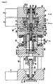
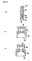
- Fig. 1 is a perspective view
- Fig. 2 is a sectional view.
- a thermoplastic resin is injection-molded
- the present invention is similarly applicable to the case where a thermoset resin, wax, and binder-treated ceramics and iron powder are injection-molded.
- the injection molding apparatus includes a plasticizing part 1 including a plasticizing block (body) 11 including, therein, a plasticizing and force-feeding mechanism which heats and plasticizes a material and force-feeds the material while kneading it, and a weighing and injecting part 3 including a weighing block (body) 31 connected to the plasticizing block 11 in close contact with it, and including, therein, a weighing and feeding mechanism which weighs and feeds out the material force-fed by the plasticizing and force-feeding mechanism.
- a plasticizing part 1 including a plasticizing block (body) 11 including, therein, a plasticizing and force-feeding mechanism which heats and plasticizes a material and force-feeds the material while kneading it
- a weighing and injecting part 3 including a weighing block (body) 31 connected to the plasticizing block 11 in close contact with it, and including, therein, a weighing and feeding mechanism which weighs and feeds out the material force-fed by the plasticizing
- the injection molding apparatus includes a mold part 2 including a fixed die plate (fixed side member) 211 including, therein, an injection mechanism which injects in a cavity, the material weighed and fed out by the weighing and feeding mechanism and is also used as a mother die of the mold, a movable die plate (movable side member) 213 which advances to and retreats from the fixed die plate 211, makes a cavity a substantially closed space when abutting on the fixed die plate 211 and is also used as the mother die of the mold, and a clamping housing (fixed side member) 212 including, therein, a movable die plate drive mechanism which is fixedly provided at a predetermined distance from the fixed die plate 211 by a plurality of tie bars 40 loosely fitted to the movable die plate 213 to guide the movable die plate 213, advances and retreats the movable die plate 213 relative to the fixed die plate 211, and generates a predetermined clamping force when the movable die plate 213 abuts on the fixed die plate
- a material input hole 13 through which a material such as pellet is inputted is formed in one side surface (the surface which is at the upper side when installed) of the plasticizing block 11.
- the plasticizing and force-feeding mechanism (kneading mechanism) is provided inside the plasticizing block 11, and the plasticizing and force-feeding mechanism includes a barrel 121 which heats the material inputted from the material input hole 13, a scroll 12 that has a spiral groove 43, which transfers the material, formed thereon and rotates while abutting on the barrel 121, thereby transferring, agitating, plasticizing, and kneading the material while the material is heated, and with the Weissenberg effect after plasticizing the material, force-feeds the material to a scroll shaft hole 44 formed in its canter of rotation.
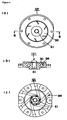
- the scroll 12 is a rotary body forming a substantially short columnar shape as shown in Fig. 3 and the like, and the spiral groove 43 is formed from a side surface of the rotary body to a surface on a fixed die plate 211 side.
- the spiral groove 43 is formed to reduce along a rotational direction of the scroll 12 to a portion near the scroll shaft hole 44 through which the injection plunger 32 formed at a rotary shaft is inserted, and a drive part engaging groove 49 formed into a concave shape is formed on its back surface.
- the scroll shaft hole 44 is also used as an injection cylinder 41.
- the surface on the fixed die plate 211 side is called a scroll working surface 47, and its side surface is called a scroll side surface 48.
- the spiral groove 43 which is formed on the scroll working surface 47 is called a feeding groove (kneading groove) 45, and the spiral groove 43 which is formed on the scroll side surface 48 is called a scraping groove (guide groove) 46. Accordingly, the spiral groove 43 is constructed by the scraping groove 46 and the feeding groove 45.
- Fig. 3(a) is a perspective view overlooking the scroll working surface 47
- Fig. 3(b) is a sectional view seen along arrows A to A in Fig. 3(a)
- Fig. 3(c) is a back view of the scroll 12.
- the scroll working surface 47 and the barrel 121 are constructed to be in close contact with each other so that the material plasticized by heat from the barrel 121 does not run out of the feeding groove 45, and the material is force-fed toward the scroll shaft hole 44 along the feeding groove 45.
- Formation of the scroll working surface 47 into the concave conical shape means that as the feeding groove 45 is closer to the scroll shaft hole 44, its groove depth becomes shallower. Accordingly, as the feeding grove 45 is closer to the scroll shaft hole 44, the direct compressive force (N) becomes larger, and reliable force-feeding becomes possible.
- Fig. 3(b) shows the case where the scroll working surface 47 is formed into the concave conical shape, but it may be formed into a convex conical shape.
- the quality of the scroll 12 is not limited to an iron metal, but the scroll 12 may be formed using, for example, brass, or a polymer resin with high heat resistance such as polytetrafluoroethylene, and polypyromellit imde as the material.
- Such a spiral groove 43 is formed by cutting with an end mill having an arc-shaped tip end vertically applied to the scroll working surface 47 (parallel with the rotary shaft of the scroll 12).
- the scraping groove 46 is formed by performing cutting with a side blade of the end mill applied to the scroll side surface 48, and while the feed amount of the end mill is gradually decreased in this state (the end mill is moved in the direction away from the scroll 12), cutting is performed along the peripheral surface of the scroll side surface 48.
- the tip end of the end mill reaches the scroll working surface 47, the feed amount of the end mill is fixed, and the scroll working surfaces 47 is cut in a spiral form up to the scroll shaft hole 44. Thereafter, the scroll working surface 47 is formed into the conical shape by cutting.
- the spiral groove 43 can be formed by a single stroke of the end mill without changing the direction of the rotary shaft of the end mill, which facilitates cutting work, and makes it possible to reduce manufacturing cost.
- the scroll 12 is not limited to one cut product, but may be produced by pouring a resin or a mental into a mold.
- the scroll drive part 42 has a worm wheel 14 with a boss attachably and detachably engaging with the drive part engaging groove 49 via a heat insulator, a worm gear 15 meshed with the worm wheel 14, a motor 4 which rotates the worm gear 15, the worm wheel 14, a thrust bearing 50 and the like, and the worm wheel 14 and the worm gear 15 constitute a speed reducing mechanism.
- the motor 4 rotates, and its rotational frequency is transmitted to the scroll 12 while reduced by the worm wheel 14 and the worm gear 15, and rotates the scroll 12.
- the barrel 121 is in a substantially disc shape with the injection cylinder 41 formed in its center, and is an internally heating type of a cartridge heater in which heater holes 84 are formed radially in the directions of the tangential lines in contact with a circle in the vicinity of the injection cylinder 41 and bar-shaped electric heaters not shown are accommodated in the heater holes 84.
- a thermometer of thermocouple or the like not shown is mountable.
- Fig. 4(a) is a view showing a surface on which the scroll working surface 47 abuts as a top view
- Fig. 4(b) is a sectional view seen along the arrows B to B in Fig. 4(a)
- Fig. 4(c) is a back view.
- the heater holes 84 are shown by the phantom lines.
- a surface 30 of the barrel 121 is formed into a conical shape in a convex form to the scroll 12 side so as to contact the scroll working surface 47, so that the surface 30 abuts on the scroll working surface 47 to thereby close the groove space of the feeding groove 45.
- the injection cylinder 41 which communicates with the scroll shaft hole 44 is formed in the center of the barrel 121, and the injection plunger 32 which will be described later is inserted into the injection cylinder 41 and performs piston movement.
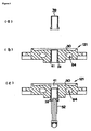
- a sleeve-shaped injection cylinder 39 as shown in Fig. 5 is capable of being inserted in accordance with the outside diameter.
- Fig. 5(a) is a sectional view of the injection cylinder 39
- Fig. 5(b) is a sectional view when the injection cylinder 39 is fitted in the injection cylinder 41
- Fig. 5(c) is a sectional view showing a state halfway through the insertion of the injection plunger 32.
- Such a barrel 121 is accommodated in and fixed to a barrel pocket 52 formed in the fixed die plate 211 and the plasticizing block 11.
- the thermal capacity and volumetric capacity of the heater can be made small, and the temperature gradient is realized at the outer peripheral portion and the center portion.
- Reduction in the thermal capacity of the heater means that the temperature controller including its power supply can be made compact in corporation with adoption of the internal heating type, and brings about the effect of being capable of suppressing excessive heat supply without using a heater of a large capacity.
- the temperature of the center portion of the barrel 121 is a melting temperature
- the temperature of the outer peripheral portion is a material melting point or lower
- the temperature of the material becomes higher toward the injection cylinder 41 from the material input hole 13 side, and therefore, the problem that the material immediately after being inputted is fused and adhesive to be in a doughboy state can be prevented. Since the material is gradually softened and compressed from the grain form, discharge of air naturally occurs, and entrainment of air by the plasticized material can be prevented.
- the cartridge heaters are used, and the construction in which the cartridge heaters are arranged in the directions of the tangential lines in contact with the circle in the vicinity of the injection cylinder 41 as shown in Fig. 7 is adopted.
- the conventional screw Since the conventional screw is formed into a columnar rod shape or a conical rod shape as described above, it has the construction in which the thermal capacities of the screw and the barrel 121 become large, a large amount of heat is required, and a long time is taken before standby with a large amount of heat release. Further, the conventional screw is externally heated and the heat release amount into the atmosphere is large, but the scroll 12 according to the present invention is of an internal heating type, and therefore, has the advantages that such heat loss is very small, and the temperature raising time is short.
- the plasticizing block 11 accommodates a heat insulator 54, and a cooling water passage 55 in which cooling water flows is formed adjacently to or in contact with the heat insulator 54.
- These heat insulator 54 and the cooling water passage 55 are each formed into a ring shape to surround the periphery of the barrel 121 to act to suppress diffusion of heat from the barrel 121 to the plasticizing block 11.
- the barrel pocket 52 in the fixed die plate 211 is properly formed to be larger than the barrel 121, so that the back surface (the mold part 2 side) of the barrel 121 forms a hollow space.
- a cooling water passage 53 in which the cooling water flows is formed in the fixed die plate 211.
- the hollow space in the barrel pocket 52 performs heat insulating action to prevent the heat of the barrel 121 from being transmitted to the mold part 2 and a hot runner 57 which will be described later via the fixed die plate 211, and the cooling water passage 53 covers a shortfall of the heat insulating action by the hollow space by allowing the cooling water to flow therein.
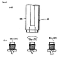
- the injection plunger 32 is inserted through the injection cylinders 39 and 41, and the hot runner 57 is provided at a tip thereof to protrude to the mold part 2 side.
- the hot runner 57 is constructed by a runner tube 58 of a hollow body, and a nozzle 59 threadedly fitted to a tip end of the runner tube 58.
- the nozzles 59 (59a to 59c) differing in the tip end shape as shown in, for example, Fig. 6 are prepared, and the nozzle 59 is used by being selected from them in accordance with the size such as a thickness of the product to be injection-molded. Accordingly, injection molding of various kinds of products is made possible by only replacing the nozzle 59, and the advantage of enhancing versatility is provided.
- the weighing block 31 in the weighing and injecting part 3 is provided with the weighing and feeding mechanism which weighs a material and feed it to the mold part 2 via the hot runner 57.
- the weighing and feeding mechanism has the injection plunger 32 which penetrates through the scroll shaft hole 44 and the like of the scroll 12, a ball screw 33 for plunger, which attachably and detachably engages with the injection plunger 32, and a plunger drive part 61 which weighs and feeds out the material force-fed to the injection plunger 32 by causing the injection plunger 32 to perform piston movement by driving the ball screw 33 for plunger.
- Fig. 7 is a view of the weighing block 31 seen from the injection plunger 32 side
- Fig. 8(a) is a sectional view showing a main part of the weighing and feeding mechanism
- Fig. 8(b) is a perspective view of the injection plunger 32.
- the injection plunger 32 forms a rod-shaped body in appearance, and has a tip end hole 69 bored from its tip end to the inside, an introduction hole 65 which is formed by being trenched in the side surface in the longitudinal direction so that a groove end at the tip end side communicates with the tip end hole 69, a feeding notch 64 which is formed by being notched along the tip end hole 69 to inject the material in the tip end hole 69, and a valve body 66 which is locked to the tip end hole 69 while being loosely fitted in the tip end hole 69 to function as a check valve which prevents backflow of the material.
- the valve body 66 is not limited to the sphere, but may be in a truncated cone shape and the like.
- Fig. 9 is a view showing a detailed construction of the injection plunger 32 when a spherical ball is used as the valve body 66
- Fig. 10 is a view of the detailed construction when the valve body 66 in a truncated con shape is used. Note that the arrows in Figs. 9 and 10 show the flow of the material, and Figs. 9(b) and 10(b) show the case where the valve body 66 moves upward, while Figs. 9(c) and 10(c) show the case where the valve body 66 moves downward.
- the injection plunger 32 is inserted through the scroll shaft hole 44 forming the injection cylinder and the injection cylinder 41, and when the pressure at the feeding notch 64 side becomes higher than the pressure at the introduction hole 65 side, the valve body 66 moves upward to shut off the communication of the feeding notch 64 and the introduction hole 65. Thereby, injection of the material is stopped.
- the valve body 66 When the pressure at the feeding notch 64 side becomes lower than the pressure at the introduction hole 65 side on the other hand, the valve body 66 is moved downward to allow the feeding notch 64 and the introduction hole 65 to communicate with each other. Thereby, injection of the material is performed.
- check valve for preventing backflow of a material
- the check valve of the conventional construction is designed to prevent the valve body form falling off by mounting a non-return ring to a tip end of a plunger with a screw with an arrow, and the problem of the screw with the arrow breaking by fatigue in several months has been pointed out.
- the check valve according to the present invention does not have the requirement of a screw structure, and therefore, does not break by fatigue, and includes the characteristic which does not causes such a problem.
- the introduction hole 65 and the like form a torpedo which reduces viscosity of a plasticized molten material and stabilizes the viscosity at the same time.
- the present invention includes such an important element indispensable for plasticization without providing a special space, and therefore, it achieves reduction in size.
- the plunger drive part 61 has a motor 6, a worm gear 37 which obtains a rotational power from the motor 6, and a worm wheel 36 which is meshed with the worm gear 37 to reduce the rotational frequency of the motor 6 to transmit it to the ball screw 33 for plunger, and thereby causes the injection plunger attachably and detachably engaged with the ball screw 33 for plunger to perform piston movement.
- the ball screw 33 for plunger has the ball screw structure, and a ball screw nut 35 is fixed to the weighing block 31. Therefore, when the ball screw 33 for plunger rotates, the ball screw 33 for plunger advances and retreats in accordance with the rotational direction.
- the injection plunger 32 is connected to the ball screw 33 for plunger, and receives the drive force from the plunger drive part 61 via the ball screw 33 for plunger to perform piston movement inside the injection cylinder.
- the construction in which the injection plunger 32 and the ball screw 33 for plunger are connected by a dovetail groove 34 as shown in Fig. 7 instead of coupling, is adopted.
- the rotational power of the ball screw 33 for plunger is transmitted from the motor 6 to the ball screw 33 for plunger via the worm gear 37 and the worm wheel 36, and on that occasion, a load is applied on the worm wheel 36 in the axial direction of the ball screw 33 for plunger. Therefore, thrust bearings 68 which bear such a load are provided to sandwich the worm wheel 36.
- the injection plunger 32 in the construction in which a ball screw and a motor of a large capacity are directly connected as conventionally adopted, and in the construction in which the injection plunger 32 is driven by hydraulic pressure or pneumatic pressure, in the control of the injection plunger 32 at the pressure hold time (injection molding time) and at the plasticizing and weighing time, the injection plunger 32 can freely retreat and release pressure in accordance with the set pressure hold value.
- a nut biasing spring 100 which abuts on the ball screw nut 35 to bias it to the injection plunger 32 side, and a load cell 101 which abuts on the nut biasing spring 100 to control a load applied to the injection plunger 32 are provided at the weighing block 31, as shown in Fig. 2 .
- the load cell 101 is controlled so that the ball screw nut 35 can slide within a stroke of, for example, 1 mm or less by the nut biasing spring 100 so as to release pressure when the valve body 66 abuts on the runner tube 58 to be able to inject the material.
- the mold is a cassette mold 22 constituted of a movable mold piece (movable side member) 222 mounted to the movable die plate 213, and a fixed mold piece (fixed side member) 221 mounted to the fixed die plate 211.
- Fig. 11 is a view showing the construction of such a cassette mold 22
- Fig. 11(a) is a front view of the fixed mold piece 221 seen from the injection plunger 32 side
- Figs. 11(b) and 11(c) are sectional views of the fixed mold piece 221 and the movable mold piece 222 seen in the arrows C to C in Fig. 11(a) .
- One mold piece 221 (222) is provided with a plurality of positioning pins 74, and the opposing mold piece 222 (221) is provided with pin receiving holes 75 in which the positioning pins 74 are fitted. Further, in the fixed mold piece 221 mounted to the fixed die plate 211, a runner receiving hole 76 in which the hot runner is inserted is formed.
- the movable mold piece 222 is provided with a molded product extruding mechanism.
- the molded product extruding mechanism includes a support plate 93 to which a plurality of extrusion pins 92 provided to penetrate through the movable mold piece 222 to be inserted through the cavity are fixed, a support rod 95 which is fixed to the support plate 93 and is inserted into the movable mold piece 222, a spring 97 which is inserted into the support rod 95 to bias the support plate 93 in normal times so that a head portion 99 of the extrusion pin 92 forms a wall surface of the cavity, an extrusion plate 94 fixed to the support plate 93, a thrust bearing 98 mounted to the extrusion plate 94, and an insertion hole 106 formed in the movable die plate 213.
- the support plate 93, the extrusion plate 94 and the support rod 95 constitute an extruding part 91.
- the thrust bearing 98 is provided so that the head portion 105 of the clamping ball screw 23 does not damage the extrusion plate 94, and it may be a thrust slide bearing or the like.
- a device that is an element of an air cylinder/piston or a mold opening and closing drive mechanism, which is reduced to about 1/5, may be included in the movable die plate though the entire length of the injection molding apparatus becomes slightly long,.
- the cassette mold 22 is a one-side opening type constituted of the fixed mold piece 221 and the movable mold piece 222 as described above, the fixed mold piece 221 is clamped to the fixed die plate 211 with a clamper 78, and the movable mold piece 222 is clamped to the movable die plate 213 with the clamper 78.
- the clampers 78 include clump claws 80 which are engaged with clamp grooves 79 respectively provided at the fixed mold piece 221 and the movable mold piece 222, clamp bolts 81 holding down the clamp claws 80, and springs not shown which bias the clamp claws 80 to open.
- the clamp bolts 81 have the tip ends each formed into a semispherical shape, or have valve bodies 66 mounted to the tip ends, and hexagonal wrench grooves are formed at rear ends, so that they are threadedly fitted to the fixed die plate 211 and the movable die plate 213.
- the clamp claws 80 are swingably mounted to the fixed die plate 211 and the movable die plate 213, and when the clamp bolts 81 are fastened, the clamp claws 80 abut on the clamp grooves 79, and press the fixed mold piece 221 and the movable mold piece 222 respectively to the fixed die plate 211 side and the movable die plate 213 side to clamp them thereto.
- the springs bias the clamp claws 80 to be away from the fixed mold piece 221 and the movable mold piece 222 to release the clamp.
- a plurality of positioning pins 74 are provided, while in the other one, a plurality of pin receiving holes 75 in which the positioning pins 74 are fitted are formed, and they form a positioning mechanism of the cassette mold 22.
- the positioning pins 74 and the pin receiving holes 75 are provided with very small tapers.
- the cassette mold 22 is a one-side opening type constituted of the fixed mold piece 221 and the movable mold piece 222, and the movable mold piece 222 abuts on the fixed mold piece 221 to constitute the cavity.
- the movable mold piece 222 and the fixed mold piece 221 are of the structure clamped to the fixed die plate 211 and the movable die plate 213, and the movable die plate 213 has the construction in which it moves by being loosely fitted to the tie bar 40. Therefore, in order to enhance the combination accuracy of the movable mold piece 222 and the fixed mold piece 221, it is necessary to enhance the clamp accuracy and loose fit accuracy.
- the movable mold piece 222 abuts on the fixed mold piece 221 and the positioning pins 74 are guided by the pin receiving holes 75 and are combined, whereby the combination accuracy of the cassette mold 22 can be ensured without requiring clamp accuracy and loose fit accuracy.
- the movable die plate drive mechanism in the clamping housing 212 has the clamping ball screw 23 which is threadedly fitted in a ball screw nut 24 mounted to the movable die plate 213, and a movable die plate drive part 27 which advances and retreats the movable die plate 213 by rotating the clamping ball screw 23 and generates a predetermined clamping force when the movable die plate 213 abuts on the fixed die plate 211.
- the movable die plate drive part 27 has a motor 5, a worm gear 26 which obtains rotational power from the motor 5, and a worm wheel 25 which is meshed with the worm gear 26 to reduce the rotational frequency of the motor 5 to transmit it to the clamping ball screw 23, and thereby advances and retreats the movable die plate 213 in which the clamping ball screw 23 is threadedly fitted.
- the speed reducing mechanism with a large speed reduction ratio constructed by the worm gears 15, 26 and 37 and the worm wheels 14, 25 and 36 are driven respectively by the motors 4, 5 and 6 with small drive capacities in the scroll drive part 42, the plunger drive part 61 and the movable die plate drive part 27, the above described problems do not occur, and reduction in size and power consumption are made possible.
- the present invention is not limited to this, and the present invention is also applicable to the case where a product made of two kinds of materials is injection-molded like two-color molding.
- a plasticizing unit is formed by one plasticizing block 11 and one weighing block, and a plurality of plasticizing units are provided to be able to inject different materials, and a clamping unit moving part not shown which moves the clamping unit constituted of one fixed die plate 211, one movable die plate 213 and one clamping housing 212 so that the materials from the plurality of plasticizing units can be injected into a cavity of one mold.
- the clamping unit is moved by the clamping unit moving part correspondingly to injection of the material of each of the plasticizing units, and thereby, multicolor molding and the like can be facilitated.
- the injection molding apparatus according to the present invention can be applied to the apparatuses which manufacture products by injection-molding a thermoplastic resin, a thermoset resin, wax, and magnetic powder, iron powder and ceramics coated with binder.
- the injection molding apparatus according to the present invention can be also used as a component manufacture and supply apparatus of an assembly line, and as a test apparatus which can be placed on a table in research and experiment.
- a molding machine of the capacity of a clamping force of 1 tf, and injection pressure of 3,000 kgf/cm 2 can be constructed with outside dimensions of a machine width of 12 cm, a machine height of 12 cm and a machine length of 36 cm.
Landscapes
- Engineering & Computer Science (AREA)
- Manufacturing & Machinery (AREA)
- Mechanical Engineering (AREA)
- Injection Moulding Of Plastics Or The Like (AREA)
- Moulds For Moulding Plastics Or The Like (AREA)
Claims (13)
- Spritzgusseinrichtung, die eine Ware durch Einspritzen eines plastifizierten Materials in das Formnest einer Form spritzt, umfassend:einen Plastifizierungsblock (11); der einen Plastifizierungs- und Zwangsfördermechanismus umfasst, der das Material erhitzt und plastifiziert und das Material zwangsfördert und gleichzeitig formt, wobei dieser Plastifizierungs- und Zwangsfördermechanismus einen Einspritzzylinder (41) aufweist;einen mit dem Plastifizierungsblock (11) in engem Kontakt verbundenen Wiegeblock (31) der einen Wiege- und Fördermechanismus umfasst, der das durch den Plastifizierungs-und Zwangsfördermechanismus zwangsgeförderte Material wiegt und weiterfördert, wobei der Wiege- und Fördermechanismus einen Einspritzkolben (32) aufweist, der durch den Einspritzzylinder (41) eingeführt ist;eine feste Düsenkopfplatte (211), die einen Einspritzmechanismus umfasst, der das durch den Wiege- und Förderungsmechanismus gewogene und weitergeförderte Material in ein Formnest einspritzt;eine bewegliche Düsenkopfplatte (213), die an die feste Düsenkopfplatte (211) heranfährt bzw. zurückfährt und aus dem Formnest einen im Wesentlichen geschlossenen Raum bildet, wenn sie gegen die feste Düsenkopfplatte anstösst; undein Klemmgehäuse (212), das einen Antriebsmechanismus der beweglichen Düsenkopfplatte umfasst, der starr in einer vorgegebenen Entfernung von der festen Düsenkopfplatte (211) durch eine Vielzahl von Führungsstangen zur Führung der beweglichen Düsenkopfplatte (213) vorgesehen ist, die bewegliche Düsenkopfplatte (213) an die feste Düsenkopfplatte (211) heran bzw. zurückfährt, und eine vorgegebene Klemmkraft erzeugt, wenn die bewegliche Düsenkopfplatte (213) gegen die feste Düsenkopfplatte (211) anstösst,dadurch gekennzeichnet, dass der Einspritzkolben (32),ein Loch (69) in seinem spitzen Ende aufweist, das durch eine Bohrung in der Oberfläche des spitzen Endes ausgebildet ist,ein Einführungsloch (65) aufweist, das durch eine längslaufende Einkerbung in der Seitenfläche ausgebildet ist und derart ausgebildet ist, dass ein Nutenende auf der Seite des spitzen Endes mit dem Loch (69) in dem spitzen Ende in Verbindung steht,eine Zufuhrkerbe (64) aufweist, die durch eine längslaufende Einkerbung des Lochs (69) im spitzen Ende ausgebildet ist und das Material aus dem Loch (69) im spitzen Ende hinausbefördert, undeinen Ventilkörper (66) aufweist, der an dem Loch (69) im spitzen Ende fixiert ist und gleichzeitig locker in dem Loch (69) im spitzen Ende sitzt, der das Einspritzen des Materials durch Abschliessen der Verbindung zwischen der Zufuhrkerbe (63) und dem Einführungsloch (65) dann abbricht, wenn der Druck auf der Seite der Zufuhrkerbe (64) höher wird als der Druck auf der Seite des Einführungslochs (65) und der wenn der Druck auf der Seite der Zufuhrkerbe (64) niedriger wird als der Druck auf der Seite des Einführungslochs (65), das Einspritzen des Materials dadurch erlaubt, dass er eine Verbindung zwischen der Zufuhrkerbe (64) und dem Einführungsloch (65) erstellt.
- Spritzgusseinrichtung nach Anspruch 1,
wobei der Plastifizierungs- und Zwangsfördermechanismus,
einen Zylinder (121) aufweist, der das Material erhitzt und plastifiziert,
eine Schnecke (12) eines im Wesentlichen kurzen säulenförmigen drehbaren Körpers aufweist, die eine Spiralnut (43) zum Weiterleiten des darin geformten Materials aufweist, die Plastifizierung und das Formen des Materials in der Spiralnut (43) durch Drehung begünstigt während sie auf gleicher Ebene mit dem Zylinder in Kontakt steht, und das Material in den um deren Drehpunkt ausgebildeten Einspritzzylinder zwangsbefördert und
einen Schneckenantriebsteil (42) aufweist, der die Schnecke dreht (12). - Spritzgusseinrichtung nach Anspruch 2,
wobei jeweilige aneinandergrenzende Flächen der Schnecke (12) und des Zylinders (121) kegelförmig ausgebildet sind. - Spritzgusseinrichtung nach Anspruch 3,
wobei jeweilige aneinandergrenzende Flächen der Schnecke (12) und des Zylinders (121) konkav kegelförmig mit einer Aussparung auf der Seite der Schnecke (12) ausgebildet sind. - Spritzgusseinrichtung nach einem der Ansprüche 2, 3 oder 4,
wobei die Spiralnut (43) in der Schnecke (12)
eine Kratznut (46) aufweist, die durch Schneiden mit einem an einer Seitenfläche eines drehbaren Körpers parallel zur Drehachse der Schnecke (12) angesetzten Schaftfräser ausgebildet wird und das Schaben des Materials übernimmt, und
eine Zufuhrnut (45) aufweist, die von der Kratznut (46) ausgehend durch fortlaufendes Schneiden einer Stirnfläche des drehbaren Körpers in eine in Richtung auf den Drehpunkt abnehmende Spiralform ausgebildet ist und das Weiterleiten, die Plastifizierung, das Formen und die Zwangsförderung des gekratzten Materials übernimmt. - Spritzgusseinrichtung nach Anspruch 5,
wobei der Schneckenantriebsteil (42),
ein Schneckengetriebe (15) aufweist, das seine Rotationsantriebskraft von einem Motor (4) gewinnt, und
ein Schneckenrad (14) aufweist, das mit dem Schneckengetriebe (15) in Eingriff steht, um die Drehzahl des Motors (4) zu reduzieren und sowohl verbindbar als auch abtrennbar über eine Wärmeisolationsplatte mit der Schnecke (12) eingreift, um die Schnecke (12) mit einer reduzierten Drehzahl zu drehen. - Spritzgusseinrichtung nach einem der vorhergehenden Ansprüche,
wobei der Wiege- und Fördermechanismus,
einen Kugelgewindetrieb (33) für einen Kolben aufweist, der durch eine Schwalbenschwanznut (34) sowohl verbindbar als auch abtrennbar mit dem Einspritzkolben (32) eingreift, und
ein Kolbenantriebsteil (61) aufweist, das den Kugelgewindetrieb (33) für einen Kolben antreibt, damit der Einspritzkolben (32) eine Kolbenbewegung in dem Einspritzzylinder (41) durchführt, und dabei eine Förderkraft für das zwangsgeförderte Material auf den Einspritzkolben (32) ausübt. - Spritzgusseinrichtung nach einem der vorhergehenden Ansprüche,
wobei der Einspritzmechanismus,
einen Heisskanal (57) umfasst, in dem das durch den Einspritzkolben (32) geförderte Material fliesst,
eine Düse (59) umfasst, die das Material in das Formnest einspritzt, in dem sie gemäss dem zu spritzenden Produkt ausgewählt wird und an einem spitzen Ende des Heisskanals (57) befestigt wird, und
ein Loch in dem Heisskanal umfasst, das den Heisskanal (57) und die Düse (59) derart beherbergt, dass sie in das Loch eingefügt bzw. aus dem Loch entnommen werden können. - Spritzgusseinrichtung nach Anspruch 8,
wobei das Kolbenantriebtsteil (61)
ein Schneckengetriebe (37) aufweist, das seine Rotationsantriebskraft von einem Motor (6) gewinnt, und
ein Schneckenrad (36) aufweist, das mit dem Schneckengetriebe (37) in Eingriff steht, um die Drehzahl des Motors (6) zu reduzieren und einem Kugelgewindetrieb (33) für einen Kolben zu übermitteln und dabei eine Kolbenbewegung des sowohl verbindbar als auch abtrennbar mit dem Kugelgewindetrieb (33) für einen Kolben eingreifenden Einspritzkolbens (32) zu bewirken - Spritzgusseinrichtung nach Anspruch 9,
wobei der Antriebsmechanismus der beweglichen Düsenkopfplatte,
einen klemmenden Kugelgewindetrieb (23) aufweist, der über ein Gewinde an einer Nut (24) des Kugelgewindetriebs angebracht ist, die an der beweglichen Düsenkopfplatte (213) befestigt ist,
ein Schneckengetriebe (26) aufweist, das seine Rotationsantriebskraft von einem Motor (5) gewinnt, und
ein Schneckenrad (25), das mit dem Schneckengetriebe (26) in Eingriff steht, um die Drehzahl des Motors (5) zu reduzieren und dem klemmenden Kugelgewindetrieb (23) zu übermitteln und dabei die bewegliche Düsenkopfplatte (213) heranfährt und zurückfährt. - Spritzgusseinrichtung nach einem der vorhergehenden Ansprüche,
wobei eine Form, die das Formnest bildet,
ein festes Formteil (221) aufweist, das an der festen Düsenkopfplatte (211) befestigt ist,
ein bewegliches Formteil (222) aufweist, das an der beweglichen Düsenkopfplatte (213) befestigt ist und aus einem im Wesentlichen geschlossenen Raum ein Formnest dann bildet, wenn die bewegliche Düsenkopfplatte (213) an der festen Düsenkopfplatte (211) anstösst,
einen Kegelstift aufweist, der entweder in dem beweglichen Formteil (222) oder an dem festen Formteil (221) ausgebildet ist,
ein kegelförmiges Loch aufweist, das in dem anderen Formteil ausgebildet ist und mittels des in das Loch eingeführten Kegelstifts eine Positionierung durchführt, wenn das bewegliche Formteil (222) an dem festen Formteil (221) anstösst. - Spritzgusseinrichtung nach Anspruch 11, ferner umfassend:ein Extrusionsteil (91), an dem eine Vielzahl von Extrusionsdornen (92) befestigt sind, die dazu vorgesehen sind, in das bewegliche Formteil (22), das durch das Formnest eingeführt werden soll, vorzudringen;eine Feder (97), die das Extrusionsteil (91) derart beeinflusst, dass Kopfteile (99) der Extrusionsdorne (92) normalerweise eine Wandung des Formnests bilden; undein Einführungsloch (106), das in der beweglichen Düsenkopfplatte (213) ausgebildet ist und einem Kopfteil (105) des klemmenden Kugelgewindetriebs (23) ermöglicht, durch die bewegliche Düsenkopfplatte zu dringen, gegen das Extrusionsteil (91) zu stossen, das Extrusionsteil (91) zur Seite des Formnests gegen die Feder (97) zu drücken, und dabei ein gespritztes Produkt in dem Formnest dann zu extrudieren, wenn die bewegliche Düsenkopfplatte (213) um einen vorgegebenen Abstand oder mehr in Richtung Klemmgehäuse (212) zurückfährt.
- Spritzgusseinrichtung nach einem der vorhergehenden Ansprüche,
in der eine Vielzahl von Plastifiziereinheiten vorgesehen ist, die alle aus einem Plastifizierungsblock (11) und einem Wiegeblock (31) bestehen, eine Klemmeinheit vorgesehen ist, die aus einer festen Düsenkopfplatte (211), einer beweglichen Düsenkopfplatte (213) und einem Klemmgehäuse besteht, und ein Teil zum Bewegen der Klemmeinheit vorgesehen ist, das die Klemmeinheit ensprechend zu jeder der Plastifiziereinheiten bewegt, so dass verschiedene Materialien in ein Formnest eingespritzt werden können.
Applications Claiming Priority (2)
| Application Number | Priority Date | Filing Date | Title |
|---|---|---|---|
| JP2004087482 | 2004-03-24 | ||
| PCT/JP2005/005335 WO2005090050A1 (ja) | 2004-03-24 | 2005-03-24 | 射出成形装置及び射出成形装置用スクロール |
Publications (3)
| Publication Number | Publication Date |
|---|---|
| EP1733863A1 EP1733863A1 (de) | 2006-12-20 |
| EP1733863A4 EP1733863A4 (de) | 2010-01-13 |
| EP1733863B1 true EP1733863B1 (de) | 2011-11-02 |
Family
ID=34993528
Family Applications (1)
| Application Number | Title | Priority Date | Filing Date |
|---|---|---|---|
| EP05727115A Expired - Lifetime EP1733863B1 (de) | 2004-03-24 | 2005-03-24 | Spritzgiessvorrichtung |
Country Status (6)
| Country | Link |
|---|---|
| US (1) | US7520739B2 (de) |
| EP (1) | EP1733863B1 (de) |
| KR (1) | KR101172550B1 (de) |
| CN (1) | CN100566972C (de) |
| AT (1) | ATE531503T1 (de) |
| WO (1) | WO2005090050A1 (de) |
Families Citing this family (26)
| Publication number | Priority date | Publication date | Assignee | Title |
|---|---|---|---|---|
| WO2007119533A1 (ja) * | 2006-04-10 | 2007-10-25 | Shinko Sellbic Co., Ltd. | スクロール、バレル及び射出成形機 |
| JP2009143008A (ja) * | 2007-12-11 | 2009-07-02 | Denso Corp | 金型装置 |
| JP5547905B2 (ja) * | 2009-04-06 | 2014-07-16 | 株式会社東洋精機製作所 | 樹脂押出し加工装置 |
| JP2012158127A (ja) * | 2011-02-02 | 2012-08-23 | Shin-Etsu Chemical Co Ltd | 液状付加硬化型シリコーンゴム組成物の射出成形方法及びその成形品 |
| CN102490309B (zh) * | 2011-12-13 | 2013-11-20 | 北京化工大学 | 一种全电动微型精密注射成型机 |
| CA2957123C (en) * | 2014-08-05 | 2022-10-18 | Starfort Des Stubenruss Moritz | Printer head with a granule/liquid flow adjusting device supplied with granules and/or liquids |
| CN105415568B (zh) * | 2015-11-17 | 2018-04-17 | 苏州康尼格电子科技股份有限公司 | 低压注胶装置、低压封胶系统及低压封胶方法 |
| CN107415181A (zh) * | 2017-05-31 | 2017-12-01 | 杨海波 | 微型注塑机 |
| DE102017005903A1 (de) * | 2017-06-22 | 2018-12-27 | Stack Mold Plus UG (haftungsbeschränkt) | Vorrichtung zum Festsetzen und/oder Lösen von Spritzgussformen, Mittel und Verfahren |
| JP7147324B2 (ja) * | 2018-07-25 | 2022-10-05 | セイコーエプソン株式会社 | 材料可塑化装置 |
| JP7238428B2 (ja) * | 2019-01-28 | 2023-03-14 | セイコーエプソン株式会社 | 可塑化装置、可塑化方法および三次元造形装置 |
| CN109702971A (zh) * | 2019-03-07 | 2019-05-03 | 无锡模达科技有限公司 | 一种油箱阀的阀体及其模具 |
| JP7218646B2 (ja) * | 2019-03-27 | 2023-02-07 | セイコーエプソン株式会社 | 材料供給装置、射出成形装置及び三次元造形装置 |
| JP7272091B2 (ja) * | 2019-04-24 | 2023-05-12 | セイコーエプソン株式会社 | 三次元造形装置 |
| JP7375494B2 (ja) * | 2019-11-25 | 2023-11-08 | セイコーエプソン株式会社 | 可塑化装置、射出成形機及び三次元造形装置 |
| JP7400410B2 (ja) * | 2019-11-29 | 2023-12-19 | セイコーエプソン株式会社 | 可塑化装置 |
| JP7434890B2 (ja) * | 2019-12-26 | 2024-02-21 | セイコーエプソン株式会社 | 射出成形機、および、射出成形機の制御方法 |
| JP7494569B2 (ja) * | 2020-05-27 | 2024-06-04 | セイコーエプソン株式会社 | 可塑化装置、射出成形装置および三次元造形装置 |
| JP7516869B2 (ja) | 2020-05-28 | 2024-07-17 | セイコーエプソン株式会社 | 可塑化装置、射出成形装置、及び、三次元造形装置 |
| JP7487574B2 (ja) | 2020-06-15 | 2024-05-21 | セイコーエプソン株式会社 | 射出成形装置および方法 |
| JP7533006B2 (ja) | 2020-08-19 | 2024-08-14 | セイコーエプソン株式会社 | 射出成形システム |
| JP7683334B2 (ja) | 2021-06-07 | 2025-05-27 | セイコーエプソン株式会社 | 可塑化装置、射出成形装置、および三次元造形装置 |
| JP7697304B2 (ja) * | 2021-07-28 | 2025-06-24 | セイコーエプソン株式会社 | 可塑化装置、三次元造形装置および射出成形装置 |
| CN116238091A (zh) * | 2023-03-09 | 2023-06-09 | 浙江钜裕机械设备有限公司 | 双色注射橡胶机 |
| CN116748488B (zh) * | 2023-08-17 | 2023-11-24 | 宁波爱柯迪半固态成型技术有限公司 | 一种高固相半固态前模转向局部挤压机构及其装配方法 |
| KR102706500B1 (ko) | 2024-07-17 | 2024-09-13 | 에버그린텍(주) | 정밀주조용 세라믹 코어 사출장치 |
Family Cites Families (28)
| Publication number | Priority date | Publication date | Assignee | Title |
|---|---|---|---|---|
| US2873478A (en) * | 1957-02-18 | 1959-02-17 | Nat Ind Products Company | Injection molding machine with weighfeeder and plunger position control |
| FR1262650A (fr) * | 1960-04-20 | 1961-06-05 | Etablissements Andouart Soc D | Machine à extruder |
| NL132736C (de) * | 1963-12-06 | 1900-01-01 | ||
| US3346683A (en) * | 1964-06-01 | 1967-10-10 | Owens Illinois Inc | Method and apparatus for extruding thermoplastic material |
| US3355764A (en) * | 1965-07-08 | 1967-12-05 | Hercules Inc | Injection molding apparatus |
| US3405210A (en) * | 1966-03-18 | 1968-10-08 | Owens Illinois Inc | Method and apparatus for extruding plastic material |
| BE682755A (de) * | 1966-06-17 | 1966-12-01 | ||
| DE1803258A1 (de) * | 1968-10-16 | 1970-05-21 | Basf Ag | Plastifizier- und Foerdervorrichtung zum Extrudieren und Spritzgiessen thermoplastischer Massen |
| FR1596699A (de) * | 1968-11-28 | 1970-06-22 | ||
| FR2038661A5 (de) * | 1969-03-21 | 1971-01-08 | Sidel Sa | |
| FR2131901A1 (en) * | 1971-04-02 | 1972-11-17 | Tesse Alain | Centrepetal plasticization unit - having a diminishing spiral groove to generate a high output pressure |
| JPS61209541A (ja) * | 1985-03-12 | 1986-09-17 | レオン自動機株式会社 | 寸法および流量の一定した生地帯の連続生産装置 |
| JPS61262107A (ja) * | 1985-05-16 | 1986-11-20 | Seiko Epson Corp | 樹脂可塑化機構 |
| DE3782058T2 (de) * | 1986-07-12 | 1993-04-15 | Fly Fishing Techn Ltd | Verfahren und vorrichtung zur herstellung von angelschnueren. |
| GB2202783B (en) * | 1987-03-10 | 1991-06-19 | Warburton Pitt Steven Ronald F | Extruder |
| JPH0653039B2 (ja) * | 1987-04-01 | 1994-07-20 | レオン自動機株式会社 | パン生地等の均一な連続生地の供給方法及び装置 |
| US4867665A (en) * | 1988-07-07 | 1989-09-19 | Nakatani Kikai Kabushiki Kaisha | Plastic material molding apparatus |
| JP2691035B2 (ja) * | 1989-11-10 | 1997-12-17 | 三菱重工業株式会社 | 可塑化装置 |
| JP2507148B2 (ja) * | 1990-03-05 | 1996-06-12 | 株式会社小松製作所 | 射出成形機の樹脂特性検出方法および射出制御方法 |
| JPH0736729Y2 (ja) | 1991-07-26 | 1995-08-23 | 株式会社新興セルビック | カセット式の樹脂成形用金型 |
| JPH07164494A (ja) | 1993-12-14 | 1995-06-27 | Tsuoisu Kk | 射出成形機の可塑化・射出装置 |
| JPH07223248A (ja) | 1994-02-10 | 1995-08-22 | Shinko Sellbick:Kk | 混練装置の加熱構造 |
| JPH09141688A (ja) * | 1995-11-20 | 1997-06-03 | Towa Kk | 電子部品の射出成形方法及び装置 |
| FI960768A0 (fi) * | 1996-02-20 | 1996-02-20 | Conenor Oy | Foerfarande och anordning foer att pressa plast i en form och en plastprodukt framstaelld med hjaelp av en form |
| JPH10272656A (ja) | 1997-03-28 | 1998-10-13 | Aisin Seiki Co Ltd | 中空製品の成形法およびそのための装置 |
| JP2000094485A (ja) | 1998-09-17 | 2000-04-04 | Ge Toshiba Silicones Co Ltd | 射出成形機用スクリュー |
| JP4787396B2 (ja) | 2000-06-13 | 2011-10-05 | 勝治 庄司 | セルフロック機能を有する減速装置、及びそれを用いた巻上機 |
| JP3910803B2 (ja) | 2001-04-02 | 2007-04-25 | 東芝機械株式会社 | 射出成形機における金型保護方法 |
-
2005
- 2005-03-24 KR KR1020067019442A patent/KR101172550B1/ko not_active Expired - Lifetime
- 2005-03-24 AT AT05727115T patent/ATE531503T1/de active
- 2005-03-24 US US10/592,889 patent/US7520739B2/en not_active Expired - Lifetime
- 2005-03-24 CN CNB2005800095443A patent/CN100566972C/zh not_active Expired - Lifetime
- 2005-03-24 WO PCT/JP2005/005335 patent/WO2005090050A1/ja not_active Ceased
- 2005-03-24 EP EP05727115A patent/EP1733863B1/de not_active Expired - Lifetime
Also Published As
| Publication number | Publication date |
|---|---|
| US20070184146A1 (en) | 2007-08-09 |
| CN1933955A (zh) | 2007-03-21 |
| ATE531503T1 (de) | 2011-11-15 |
| KR20070012800A (ko) | 2007-01-29 |
| EP1733863A4 (de) | 2010-01-13 |
| WO2005090050A1 (ja) | 2005-09-29 |
| KR101172550B1 (ko) | 2012-08-08 |
| EP1733863A1 (de) | 2006-12-20 |
| US7520739B2 (en) | 2009-04-21 |
| CN100566972C (zh) | 2009-12-09 |
Similar Documents
| Publication | Publication Date | Title |
|---|---|---|
| EP1733863B1 (de) | Spritzgiessvorrichtung | |
| JP4444147B2 (ja) | 射出成形装置及び射出成形装置用スクロール | |
| JP6758312B2 (ja) | 射出成形システムおよび部品製造方法 | |
| JP6250128B1 (ja) | 射出成形機 | |
| EP2767383B1 (de) | Spritzgießmaschine | |
| CN110103401B (zh) | 超声塑化微注射成型机主体及成型方法 | |
| JP6281999B1 (ja) | 射出成形機 | |
| JP2020044845A (ja) | 成形機および部品成形方法 | |
| CN104608344B (zh) | 注塑成型机 | |
| CN110653990A (zh) | 一种射出成型机及注塑成型工艺 | |
| JP2007001268A (ja) | プリプラ式射出成形装置 | |
| CN115091695B (zh) | 一种pp瓶坯单级微保压电动塑化倒置式注射装置 | |
| CN209888024U (zh) | 一种射出成型机 | |
| CN106626286A (zh) | 注射与塑化同轴线的微型注塑机 | |
| EP2774742A1 (de) | Spritzgießmaschine | |
| JP2007030390A (ja) | 射出成形機 | |
| CN110653991A (zh) | 一种用于射出成型机的转模台 | |
| CN105751455B (zh) | 螺盘与柱塞组合式注射成型装置 | |
| KR20120086933A (ko) | 분리형 가소화 스크류를 구비하는 사출성형기 | |
| CN209971342U (zh) | 超声塑化微注射成型机主体 | |
| CN207747321U (zh) | 一种注塑机射出机构 | |
| KR20180081159A (ko) | 부품 몰딩 방법 | |
| CN109476060B (zh) | 模具用注射装置安装板以及模具 | |
| JP3459214B2 (ja) | 予備可塑化式射出装置 | |
| CN209832394U (zh) | 一种用于射出成型机的熔胶部件 |
Legal Events
| Date | Code | Title | Description |
|---|---|---|---|
| PUAI | Public reference made under article 153(3) epc to a published international application that has entered the european phase |
Free format text: ORIGINAL CODE: 0009012 |
|
| 17P | Request for examination filed |
Effective date: 20061023 |
|
| AK | Designated contracting states |
Kind code of ref document: A1 Designated state(s): AT BE BG CH CY CZ DE DK EE ES FI FR GB GR HU IE IS IT LI LT LU MC NL PL PT RO SE SI SK TR |
|
| DAX | Request for extension of the european patent (deleted) | ||
| A4 | Supplementary search report drawn up and despatched |
Effective date: 20091216 |
|
| 17Q | First examination report despatched |
Effective date: 20100329 |
|
| RIC1 | Information provided on ipc code assigned before grant |
Ipc: B29C 45/17 20060101AFI20110309BHEP Ipc: B29C 45/46 20060101ALI20110309BHEP |
|
| RTI1 | Title (correction) |
Free format text: INJECTION MOLDING APPARATUS |
|
| GRAP | Despatch of communication of intention to grant a patent |
Free format text: ORIGINAL CODE: EPIDOSNIGR1 |
|
| GRAS | Grant fee paid |
Free format text: ORIGINAL CODE: EPIDOSNIGR3 |
|
| GRAA | (expected) grant |
Free format text: ORIGINAL CODE: 0009210 |
|
| AK | Designated contracting states |
Kind code of ref document: B1 Designated state(s): AT BE BG CH CY CZ DE DK EE ES FI FR GB GR HU IE IS IT LI LT LU MC NL PL PT RO SE SI SK TR |
|
| REG | Reference to a national code |
Ref country code: GB Ref legal event code: FG4D |
|
| REG | Reference to a national code |
Ref country code: CH Ref legal event code: EP |
|
| REG | Reference to a national code |
Ref country code: IE Ref legal event code: FG4D |
|
| REG | Reference to a national code |
Ref country code: CH Ref legal event code: NV Representative=s name: RENTSCH PARTNER AG |
|
| REG | Reference to a national code |
Ref country code: DE Ref legal event code: R096 Ref document number: 602005030958 Country of ref document: DE Effective date: 20111229 |
|
| REG | Reference to a national code |
Ref country code: NL Ref legal event code: VDEP Effective date: 20111102 |
|
| LTIE | Lt: invalidation of european patent or patent extension |
Effective date: 20111102 |
|
| PG25 | Lapsed in a contracting state [announced via postgrant information from national office to epo] |
Ref country code: LT Free format text: LAPSE BECAUSE OF FAILURE TO SUBMIT A TRANSLATION OF THE DESCRIPTION OR TO PAY THE FEE WITHIN THE PRESCRIBED TIME-LIMIT Effective date: 20111102 Ref country code: IS Free format text: LAPSE BECAUSE OF FAILURE TO SUBMIT A TRANSLATION OF THE DESCRIPTION OR TO PAY THE FEE WITHIN THE PRESCRIBED TIME-LIMIT Effective date: 20120302 |
|
| PG25 | Lapsed in a contracting state [announced via postgrant information from national office to epo] |
Ref country code: PL Free format text: LAPSE BECAUSE OF FAILURE TO SUBMIT A TRANSLATION OF THE DESCRIPTION OR TO PAY THE FEE WITHIN THE PRESCRIBED TIME-LIMIT Effective date: 20111102 Ref country code: BE Free format text: LAPSE BECAUSE OF FAILURE TO SUBMIT A TRANSLATION OF THE DESCRIPTION OR TO PAY THE FEE WITHIN THE PRESCRIBED TIME-LIMIT Effective date: 20111102 Ref country code: GR Free format text: LAPSE BECAUSE OF FAILURE TO SUBMIT A TRANSLATION OF THE DESCRIPTION OR TO PAY THE FEE WITHIN THE PRESCRIBED TIME-LIMIT Effective date: 20120203 Ref country code: PT Free format text: LAPSE BECAUSE OF FAILURE TO SUBMIT A TRANSLATION OF THE DESCRIPTION OR TO PAY THE FEE WITHIN THE PRESCRIBED TIME-LIMIT Effective date: 20120302 Ref country code: NL Free format text: LAPSE BECAUSE OF FAILURE TO SUBMIT A TRANSLATION OF THE DESCRIPTION OR TO PAY THE FEE WITHIN THE PRESCRIBED TIME-LIMIT Effective date: 20111102 Ref country code: SI Free format text: LAPSE BECAUSE OF FAILURE TO SUBMIT A TRANSLATION OF THE DESCRIPTION OR TO PAY THE FEE WITHIN THE PRESCRIBED TIME-LIMIT Effective date: 20111102 Ref country code: SE Free format text: LAPSE BECAUSE OF FAILURE TO SUBMIT A TRANSLATION OF THE DESCRIPTION OR TO PAY THE FEE WITHIN THE PRESCRIBED TIME-LIMIT Effective date: 20111102 |
|
| PG25 | Lapsed in a contracting state [announced via postgrant information from national office to epo] |
Ref country code: CY Free format text: LAPSE BECAUSE OF FAILURE TO SUBMIT A TRANSLATION OF THE DESCRIPTION OR TO PAY THE FEE WITHIN THE PRESCRIBED TIME-LIMIT Effective date: 20111102 |
|
| PG25 | Lapsed in a contracting state [announced via postgrant information from national office to epo] |
Ref country code: SK Free format text: LAPSE BECAUSE OF FAILURE TO SUBMIT A TRANSLATION OF THE DESCRIPTION OR TO PAY THE FEE WITHIN THE PRESCRIBED TIME-LIMIT Effective date: 20111102 Ref country code: BG Free format text: LAPSE BECAUSE OF FAILURE TO SUBMIT A TRANSLATION OF THE DESCRIPTION OR TO PAY THE FEE WITHIN THE PRESCRIBED TIME-LIMIT Effective date: 20120202 Ref country code: CZ Free format text: LAPSE BECAUSE OF FAILURE TO SUBMIT A TRANSLATION OF THE DESCRIPTION OR TO PAY THE FEE WITHIN THE PRESCRIBED TIME-LIMIT Effective date: 20111102 Ref country code: EE Free format text: LAPSE BECAUSE OF FAILURE TO SUBMIT A TRANSLATION OF THE DESCRIPTION OR TO PAY THE FEE WITHIN THE PRESCRIBED TIME-LIMIT Effective date: 20111102 Ref country code: DK Free format text: LAPSE BECAUSE OF FAILURE TO SUBMIT A TRANSLATION OF THE DESCRIPTION OR TO PAY THE FEE WITHIN THE PRESCRIBED TIME-LIMIT Effective date: 20111102 |
|
| PG25 | Lapsed in a contracting state [announced via postgrant information from national office to epo] |
Ref country code: RO Free format text: LAPSE BECAUSE OF FAILURE TO SUBMIT A TRANSLATION OF THE DESCRIPTION OR TO PAY THE FEE WITHIN THE PRESCRIBED TIME-LIMIT Effective date: 20111102 |
|
| PLBE | No opposition filed within time limit |
Free format text: ORIGINAL CODE: 0009261 |
|
| STAA | Information on the status of an ep patent application or granted ep patent |
Free format text: STATUS: NO OPPOSITION FILED WITHIN TIME LIMIT |
|
| REG | Reference to a national code |
Ref country code: AT Ref legal event code: MK05 Ref document number: 531503 Country of ref document: AT Kind code of ref document: T Effective date: 20111102 |
|
| 26N | No opposition filed |
Effective date: 20120803 |
|
| PG25 | Lapsed in a contracting state [announced via postgrant information from national office to epo] |
Ref country code: MC Free format text: LAPSE BECAUSE OF NON-PAYMENT OF DUE FEES Effective date: 20120331 |
|
| REG | Reference to a national code |
Ref country code: DE Ref legal event code: R097 Ref document number: 602005030958 Country of ref document: DE Effective date: 20120803 |
|
| REG | Reference to a national code |
Ref country code: IE Ref legal event code: MM4A |
|
| PG25 | Lapsed in a contracting state [announced via postgrant information from national office to epo] |
Ref country code: IE Free format text: LAPSE BECAUSE OF NON-PAYMENT OF DUE FEES Effective date: 20120324 Ref country code: AT Free format text: LAPSE BECAUSE OF FAILURE TO SUBMIT A TRANSLATION OF THE DESCRIPTION OR TO PAY THE FEE WITHIN THE PRESCRIBED TIME-LIMIT Effective date: 20111102 |
|
| PG25 | Lapsed in a contracting state [announced via postgrant information from national office to epo] |
Ref country code: ES Free format text: LAPSE BECAUSE OF FAILURE TO SUBMIT A TRANSLATION OF THE DESCRIPTION OR TO PAY THE FEE WITHIN THE PRESCRIBED TIME-LIMIT Effective date: 20120213 |
|
| PG25 | Lapsed in a contracting state [announced via postgrant information from national office to epo] |
Ref country code: FI Free format text: LAPSE BECAUSE OF FAILURE TO SUBMIT A TRANSLATION OF THE DESCRIPTION OR TO PAY THE FEE WITHIN THE PRESCRIBED TIME-LIMIT Effective date: 20111102 |
|
| PG25 | Lapsed in a contracting state [announced via postgrant information from national office to epo] |
Ref country code: TR Free format text: LAPSE BECAUSE OF FAILURE TO SUBMIT A TRANSLATION OF THE DESCRIPTION OR TO PAY THE FEE WITHIN THE PRESCRIBED TIME-LIMIT Effective date: 20111102 |
|
| PG25 | Lapsed in a contracting state [announced via postgrant information from national office to epo] |
Ref country code: LU Free format text: LAPSE BECAUSE OF NON-PAYMENT OF DUE FEES Effective date: 20120324 |
|
| PG25 | Lapsed in a contracting state [announced via postgrant information from national office to epo] |
Ref country code: HU Free format text: LAPSE BECAUSE OF FAILURE TO SUBMIT A TRANSLATION OF THE DESCRIPTION OR TO PAY THE FEE WITHIN THE PRESCRIBED TIME-LIMIT Effective date: 20050324 |
|
| REG | Reference to a national code |
Ref country code: FR Ref legal event code: PLFP Year of fee payment: 11 |
|
| REG | Reference to a national code |
Ref country code: FR Ref legal event code: PLFP Year of fee payment: 12 |
|
| REG | Reference to a national code |
Ref country code: FR Ref legal event code: PLFP Year of fee payment: 13 |
|
| REG | Reference to a national code |
Ref country code: CH Ref legal event code: PCAR Free format text: NEW ADDRESS: BELLERIVESTRASSE 203 POSTFACH, 8034 ZUERICH (CH) |
|
| REG | Reference to a national code |
Ref country code: FR Ref legal event code: PLFP Year of fee payment: 14 |
|
| REG | Reference to a national code |
Ref country code: GB Ref legal event code: 732E Free format text: REGISTERED BETWEEN 20221208 AND 20221215 |
|
| REG | Reference to a national code |
Ref country code: DE Ref legal event code: R081 Ref document number: 602005030958 Country of ref document: DE Owner name: SEIKO EPSON CORP., JP Free format text: FORMER OWNER: SHINKO SELLBIC CO., LTD., TOKIO/TOKYO, JP |
|
| REG | Reference to a national code |
Ref country code: DE Ref legal event code: R082 Ref document number: 602005030958 Country of ref document: DE Representative=s name: MATHYS & SQUIRE EUROPE PATENTANWAELTE PARTNERS, DE |
|
| PGFP | Annual fee paid to national office [announced via postgrant information from national office to epo] |
Ref country code: DE Payment date: 20240130 Year of fee payment: 20 Ref country code: GB Payment date: 20240201 Year of fee payment: 20 |
|
| PGFP | Annual fee paid to national office [announced via postgrant information from national office to epo] |
Ref country code: IT Payment date: 20240212 Year of fee payment: 20 Ref country code: FR Payment date: 20240213 Year of fee payment: 20 |
|
| PGFP | Annual fee paid to national office [announced via postgrant information from national office to epo] |
Ref country code: CH Payment date: 20240401 Year of fee payment: 20 |
|
| REG | Reference to a national code |
Ref country code: DE Ref legal event code: R071 Ref document number: 602005030958 Country of ref document: DE |
|
| REG | Reference to a national code |
Ref country code: CH Ref legal event code: PL |
|
| REG | Reference to a national code |
Ref country code: GB Ref legal event code: PE20 Expiry date: 20250323 |
|
| PG25 | Lapsed in a contracting state [announced via postgrant information from national office to epo] |
Ref country code: GB Free format text: LAPSE BECAUSE OF EXPIRATION OF PROTECTION Effective date: 20250323 |