EP1738450B1 - Moteur electrique a commutation electronique et son procede de production - Google Patents
Moteur electrique a commutation electronique et son procede de production Download PDFInfo
- Publication number
- EP1738450B1 EP1738450B1 EP06723762A EP06723762A EP1738450B1 EP 1738450 B1 EP1738450 B1 EP 1738450B1 EP 06723762 A EP06723762 A EP 06723762A EP 06723762 A EP06723762 A EP 06723762A EP 1738450 B1 EP1738450 B1 EP 1738450B1
- Authority
- EP
- European Patent Office
- Prior art keywords
- laminated core
- plastic
- insulating layer
- circuit board
- fixing part
- Prior art date
- Legal status (The legal status is an assumption and is not a legal conclusion. Google has not performed a legal analysis and makes no representation as to the accuracy of the status listed.)
- Expired - Lifetime
Links
Images



Classifications
-
- H—ELECTRICITY
- H02—GENERATION; CONVERSION OR DISTRIBUTION OF ELECTRIC POWER
- H02K—DYNAMO-ELECTRIC MACHINES
- H02K3/00—Details of windings
- H02K3/46—Fastening of windings on the stator or rotor structure
- H02K3/52—Fastening salient pole windings or connections thereto
- H02K3/521—Fastening salient pole windings or connections thereto applicable to stators only
- H02K3/522—Fastening salient pole windings or connections thereto applicable to stators only for generally annular cores with salient poles
-
- H—ELECTRICITY
- H02—GENERATION; CONVERSION OR DISTRIBUTION OF ELECTRIC POWER
- H02K—DYNAMO-ELECTRIC MACHINES
- H02K11/00—Structural association of dynamo-electric machines with electric components or with devices for shielding, monitoring or protection
- H02K11/30—Structural association with control circuits or drive circuits
-
- H—ELECTRICITY
- H02—GENERATION; CONVERSION OR DISTRIBUTION OF ELECTRIC POWER
- H02K—DYNAMO-ELECTRIC MACHINES
- H02K29/00—Motors or generators having non-mechanical commutating devices, e.g. discharge tubes or semiconductor devices
- H02K29/06—Motors or generators having non-mechanical commutating devices, e.g. discharge tubes or semiconductor devices with position sensing devices
- H02K29/08—Motors or generators having non-mechanical commutating devices, e.g. discharge tubes or semiconductor devices with position sensing devices using magnetic effect devices, e.g. Hall-plates, magneto-resistors
-
- H—ELECTRICITY
- H02—GENERATION; CONVERSION OR DISTRIBUTION OF ELECTRIC POWER
- H02K—DYNAMO-ELECTRIC MACHINES
- H02K2211/00—Specific aspects not provided for in the other groups of this subclass relating to measuring or protective devices or electric components
- H02K2211/03—Machines characterised by circuit boards, e.g. pcb
-
- Y—GENERAL TAGGING OF NEW TECHNOLOGICAL DEVELOPMENTS; GENERAL TAGGING OF CROSS-SECTIONAL TECHNOLOGIES SPANNING OVER SEVERAL SECTIONS OF THE IPC; TECHNICAL SUBJECTS COVERED BY FORMER USPC CROSS-REFERENCE ART COLLECTIONS [XRACs] AND DIGESTS
- Y10—TECHNICAL SUBJECTS COVERED BY FORMER USPC
- Y10T—TECHNICAL SUBJECTS COVERED BY FORMER US CLASSIFICATION
- Y10T29/00—Metal working
- Y10T29/49—Method of mechanical manufacture
- Y10T29/49002—Electrical device making
- Y10T29/49009—Dynamoelectric machine
Definitions
- the invention relates to an electronically commutated electric motor, in particular a micromotor, and a method for its production.
- the power consumption of such fans is 0.2 ... 0.6 W for the 250 series, 0.6 ... 0.9 W for the 400F series and 0.4 mm for the 400 and 600 series. .3.0 W.
- the weight is eg
- the Series 250 is about 5 (five) grams
- the Series 400 / 400F is 17 to 27 grams
- the Series 600 is about 85 grams.
- micromotors In such micromotors is aggravating added that their components, quite comparable to those of a mechanical movement, are very delicate and therefore not very robust.
- the rotor shaft has e.g. often just the thickness of a knitting needle and can therefore be easily bent when carefree, making the engine unusable. This danger exists especially during assembly.
- Such a metal pin is wrapped with a wire end of the winding assembly of the motor, inserted through a recess in the circuit board, and then soldered to this.
- this method has its limits with a maximum wire diameter of about 0.24 mm, because with thicker wires, such a pin bends, or the hole is expanded and destroyed in the insulating material of the over-molded laminated core.
- solder the copper wire by hand on solder pads of the circuit board.
- insulation displacement contacts are used, but for the wire diameter must be greater than about 0.17 mm.
- JP 2003 180047 discloses an electric motor having the features of the preamble of claim 1.
- this object is achieved by a method according to claim 1.
- one does not need metal pins, which must be pressed into the insulation layer before, but instead a made of plastic during the injection molding fastening part is used, on which a wire portion of the winding in an appropriate manner is fastened, and the combination of plastic fastener and wire section is then inserted through an associated recess of the circuit board and then soldered to it.
- a wire section may be connected to the associated plastic fastener, e.g. be connected by being wound up on this.
- the wire section in the associated plastic fastener may be at least temporarily mechanically fastened, e.g. by pressing into a groove which is provided in this plastic fastening part, by gluing, or in any other way.
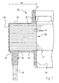
- Fig. 1 shows in a very greatly enlarged scale, with a plastic layer 20 over-molded stator lamination stack 22 of an inner stator 18 for an external rotor micro motor, the rotor magnet ring 24 in Fig. 3 indicated by dash-dotted lines. This is separated by an air gap 23 from the laminated core 22.
- the length of 1 cm indicated, ie the illustrated laminated core 22 may for example have the height of about one centimeter. A large magnification is necessary to be able to present details.
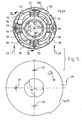
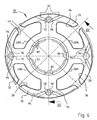
- the shape of the laminated core 22 exemplified results from Fig. 5A , This shape has four salient poles 26, 28, 30, 32, between which grooves 34, 36, 38 and 40 are located. The poles are formed on their periphery so that they generate a so-called reluctance torque during operation.
- the rotor 24 (not shown) rotates clockwise 41.
- the rotor magnet ring 24 is magnetized four-pole.
- stator 22 and rotor 24 can also use other numbers of poles for stator 22 and rotor 24, eg a version with two stator poles and two rotor poles.
- Fig. 5A shown two-strand winding, for example, a winding with only one strand, or a three-strand winding, possible.
- the laminated core 22 has on its inside a recess 42 which serves for attachment, e.g. on a bearing tube, not shown.
- the laminated core 22 is constructed in the usual way from individual sheets 44, and it is overmolded with the plastic layer 20 on its upper side 46, on its outer periphery 48 and on its underside 50.
- the plastic layer 20 merges into a collar 52, on its underside in a collar 54, and it is provided on its underside with plastic fasteners 56 which in Fig. 1 to 3 protrude down.
- plastic fasteners 56 which in Fig. 1 to 3 protrude down.
- These have approximately the shape of a pin or post and have in the example shown a square cross-section with an edge length d of about 1.5 mm.
- other elongated shapes are possible, such as a cylinder with a diameter of about 1 mm, which may also be slightly conical.
- a high-strength and high-temperature resistant plastic is preferably used, for example, a liquid-crystalline polymer, which are added to increase the strength and to reduce the anisotropy glass fibers.
- a polymer is offered under the brand TICONA, eg type "VECTRA T 135".
- TICONA temperature resistance under load
- HDT (A) temperature resistance under load
- ISO 75-1,2 at 1.8 MPa
- LCP This type of plastic is also called LCP.
- LCPs thermotropic, ie melt-processable, liquid crystalline polymers (LCPs) with very high temperature resistance. Characteristic is their molecular structure. These polymers consist of rigid, rod-shaped macromolecules, which parallelize in the melt and form liquid-crystalline structures. Subjecting this polymer melt a shear or expansion flow, z. As in injection molding, then arrange the rigid macromolecules to fibers and fibrils. These are “frozen” on cooling. This results in the specific morphology of the liquid crystalline polymers in their solid state, and this is not dissimilar to the morphology of wood. In the matrix of the LCP fibers of the same polymer are incorporated.
- such polymers are also referred to as "self-reinforcing polymers".
- the rigid, rod-shaped polymer structure leads to a considerable improvement in the mechanical properties and a few other unusual properties, namely a continuous service temperature of up to 300 ° C., a melting temperature of up to 370 ° C., a very high Tensile strength and a high modulus in the flow direction, and a high impact resistance.
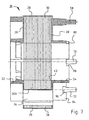
- Fig. 2 shows the laminated core 22 of Fig. 1 on which a winding 60 made of enameled copper wire has been wound, wherein the plastic parts 20, 52, 54 form a wound body.
- the winding 60 has a lead wire 62, and this is wound around the plastic fastener 56 in the form of a small winding 64.
- This small winding 64 may in some cases be tinned by immersion in a tin bath, at the same time burning off the lining of the wire 62
- the plastic fastener 56 is introduced with the winding 64 in a recess 66 of a printed circuit board 68, and then the circuit board 68 is soldered in the usual manner, wherein the winding 64 by the solder with one of the (not shown) traces on the circuit board 68 is electrically connected.
- This operation can be fully automated.
- Fig. 4 shows a section through the fully wound laminated stator core 22 and the circuit board 68, in which a total of three plastic fasteners 56, 70 and 72 protrude.
- the solder is indicated at 74.
- Fig. 5B shows the printed circuit board 68 before being mounted on the wound laminated stator core 22.
- the assembly is symbolically indicated by arrows 69.
- the printed circuit board 68 has three recesses 58 ', 70' and 72 'for receiving the three mounting members 58, 70 and 72. Further they have in their center a recess 76 into which protrude three projections 78, which serve to guide the circuit board 68 at corresponding recesses 80 of the collar 52 and are distributed asymmetrically in order to eliminate errors during assembly.
- a Hall sensor 82 is arranged, which is controlled by the stray field of the rotor magnet 24 and serves to control the electronic commutation.
- Fig. 5A shows the two winding strands 86, 88 of the exemplified engine design. These are wound in the usual way bifilar, ie with two parallel wires, and have a common terminal 90 which is mechanically connected to the plastic fastening part 70. From this, the strand 86 goes in a clockwise direction to its end 86E, which is mechanically connected to the fastening part 58. Also, from terminal 90, strand 88 goes counterclockwise to its end 88E, which is mechanically connected to fastener 72. By soldering to the circuit board 68, the strands 86, 88 are then electrically connected to corresponding, not shown interconnects of the circuit board 68. The currents through the strands 86, 88 are in a known manner, depending on the position of the rotor 24, controlled by the Hall sensor 82. Alternatively, a control according to the so-called sensorless principle is possible.
- Fig. 6 shows that there are also in the three o'clock position, to which in this example no fastening part is necessary, such protective walls 94 are provided. They are, as well as the fastening parts 58, 70, 72, formed from the material of the insulating layer 20.
- FIGS. 8 and 9 show a variant, namely a plastic fastening part 56 ', in which a longitudinal groove 57 is provided, in which a connecting wire 62' is mechanically fixed by clamping.
- a plastic fastening part 56 ' in which a longitudinal groove 57 is provided, in which a connecting wire 62' is mechanically fixed by clamping.
- This allows the attachment of thicker wires, eg with a diameter over 0.6 mm. These then do not have to be wound around the relevant fastening part.
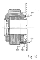
- Fig. 10 shows an attachment of the leads to metal pins 100 according to the prior art. These pins are pressed into holes 102 of an insulating layer 104, but are only suitable for very thin winding wires up to about 0.25 mm in diameter, as they can be easily damaged by excessive mechanical stress.
Landscapes
- Engineering & Computer Science (AREA)
- Power Engineering (AREA)
- Insulation, Fastening Of Motor, Generator Windings (AREA)
Abstract
Claims (22)
- Procédé de fabrication d'un moteur électrique à commutation électronique, lequel présente un stator intérieur (18) et un rotor extérieur (24) qui sont séparés l'un de l'autre par un entrefer (23),lequel stator intérieur (18) présente un empilage ou paquet de tôles (22) qui est pourvu d'un agencement d'enroulements (60 ; 86, 88) dont les connexions (62 ; 62', 86E, 88E, 90) sont formées au moins partiellement de fil métallique,et avec une carte de circuits imprimés (68) associée à l'agencement d'enroulements, laquelle est pourvue d'évidements (58', 70', 72'),lequel procédé présente les étapes suivantes :a) l'empilage ou paquet de tôles (22) du stator intérieur (18) est pourvu au moins en partie d'une couche isolante (20) qui présente une matière plastique thermiquement stable ;b) sur cette couche isolante (20) sont formées des pièces de fixation en matière plastique (56, 70, 72) qui font saillie du stator intérieur (18) en direction de la carte de circuits imprimés (68) ;c) l'empilage ou paquet de tôles (22) muni de la couche isolante (20) est bobiné avec l'agencement d'enroulements (60, 86, 88) ;d) une portion de fil (62 ; 62', 86E, 88E, 90) de l'agencement d'enroulements (60) est appliquée sur une pièce de fixation en matière plastique (58) associée ;e) la portion de fil (62 ; 62', 86E, 88E, 90) est étamée ;f) la pièce de fixation en matière plastique (58) avec la portion de fil étamée (62 ; 62', 86E, 88E, 90) appliquée dessus est introduite dans un évidement associé (58') de la carte de circuits imprimés (68) ;g) la portion de fil (62; 62', 86E, 88E, 90) introduite conjointement avec la pièce de fixation en matière plastique (58) est soudée avec la carte de circuits imprimés (68).
- Procédé selon la revendication 1, dans lequel la portion de fil (62 ; 62', 86E, 88E, 90) est bobinée autour de la pièce de fixation en matière plastique (58) associée.
- Procédé selon l'une des revendications précédentes, dans lequel l'empilage ou paquet de tôles (22) est pourvu d'une couche isolante (20) continue dans sa zone périphérique (48) tournée vers l'entrefer (23).
- Procédé selon l'une des revendications précédentes, dans lequel l'empilage ou paquet de tôles (22) est pourvu dans la zone d'une pièce de fixation en matière plastique (56, 70, 72) d'au moins une paroi (94) qui est formée d'une seule pièce avec la couche isolante (20) de l'empilage ou paquet de tôles (22).
- Procédé selon la revendication 4, dans lequel l'empilage ou paquet de tôles (22) est pourvu dans la zone d'une pièce de fixation en matière plastique (56, 70, 72) de deux parois (94) qui partent d'un renfoncement (96), dans lequel renfoncement cette pièce de fixation en matière plastique (58, 70, 72) est disposée.
- Procédé selon la revendication 4 ou 5, dans lequel la paroi (94) s'étend essentiellement dans la zone comprise entre l'empilage ou paquet de tôles (22) et la carte de circuits imprimés (68).
- Procédé selon l'une des revendications précédentes, dans lequel la couche isolante (20) et ladite au moins une pièce de fixation en matière plastique (58, 70, 72) sont réalisées dans une matière plastique thermiquement stable à laquelle est ajoutée une matière de remplissage, en particulier issue du groupe des fibres de verre et du mica.
- Procédé selon l'une des revendications précédentes, dans lequel on utilise au moins principalement un polymère à cristaux liquides comme matière plastique résistante aux températures élevées.
- Procédé selon la revendication 8, dans lequel des fibres de verre ou analogues sont ajoutées au polymère à cristaux liquides.
- Procédé selon l'une des revendications précédentes, dans lequel l'empilage ou paquet de tôles (22) présente des encoches (34, 36, 38, 40) dont l'intérieur est pourvu d'une couche isolante (20N) composée du polymère à cristaux liquides.
- Moteur électrique à commutation électronique, lequel présente un stator intérieur (18) et un rotor extérieur (24) qui sont séparés l'un de l'autre par un entrefer (23), lequel stator intérieur (18) présente un empilage ou paquet de tôles (22) qui est pourvu au moins en partie d'une couche isolante (20) qui présente une matière plastique thermiquement stable et est bobiné avec un agencement d'enroulements (60, 86, 88) dont les connexions sont réalisées au moins partiellement sous la forme de portions de fil (62 ; 62' ; 86E, 88E, 90),
et avec une carte de circuits imprimés (68) associée à l'agencement d'enroulements (60, 86, 88), laquelle est pourvue d'évidements (58', 70', 72'), des pièces de fixation en matière plastique (56, 70, 72) étant formées sur la couche isolante (20) prévue sur l'empilage ou paquet de tôles (22), lesquelles font saillie du stator intérieur (18) en direction de la carte de circuits imprimés (68) et sur lesquelles sont appliquées les portions de fil (62 ; 62' ; 86E, 88E, 90),
caractérisé en ce que les pièces de fixation (56, 70, 72) avec les portions de fil étamées appliquées dessus sont chaque fois disposées dans un évidement (58', 70', 72') associé de la carte de circuits imprimés (68) et y sont soudées avec la carte de circuits imprimés (68). - Moteur selon la revendication 11, dans lequel une portion de fil (62 ; 86E, 88E, 90) est bobinée autour de la pièce de fixation en matière plastique (58, 70, 72) associée.
- Moteur selon la revendication 11, dans lequel une portion de fil (62') s'étend essentiellement parallèlement à la direction longitudinale d'une pièce de fixation (58) associée et est fixée à cette dernière au moins provisoirement mécaniquement.
- Moteur selon l'une des revendications 11 à 13, dans lequel l'empilage ou paquet de tôles (22) est pourvu d'une couche continue (20) de la matière plastique thermiquement stable dans sa zone périphérique (48) tournée vers l'entrefer (23).
- Moteur selon la revendication 14, dans lequel la couche continue (20) présente une épaisseur de couche moyenne inférieure à 0,5 mm et de préférence d'environ 0,2 mm.
- Moteur selon l'une des revendications 11 à 15, dans lequel l'empilage de tôles (22) présente dans la zone d'une pièce de fixation (56, 70, 72) au moins une paroi (94) qui est formée d'une seule pièce avec la couche isolante (20) de l'empilage de tôles (22) ou paquet et fait saillie dans la direction l'éloignant de ce dernier.
- Moteur selon la revendication 16, dans lequel l'empilage de tôles ou paquet (22) présente dans la zone d'une pièce de fixation (56, 70, 72) deux parois (94) qui partent d'un renfoncement (96) dans lequel au moins une pièce de fixation (58, 70, 72) est disposée.
- Moteur selon la revendication 16 ou 17, dans lequel ladite au moins une paroi (94) s'étend essentiellement dans la zone comprise entre l'empilage ou paquet de tôles (22) et la carte de circuits imprimés (68).
- Moteur selon l'une des revendications 11 à 18, dans lequel la couche isolante (20) et ladite au moins une pièce de fixation (58, 70, 72) sont essentiellement composées d'une matière plastique thermiquement stable à laquelle est ajoutée une matière de remplissage pour augmenter sa résistance ou solidité mécanique.
- Moteur selon l'une des revendications 11 à 19, dans lequel la couche isolante (20) est composée au moins principalement d'un polymère à cristaux liquides.
- Moteur selon la revendication 20, dans lequel des fibres de verre sont ajoutées au polymère à cristaux liquides.
- Moteur selon l'une des revendications 11 à 21, dans lequel l'empilage ou paquet de tôles (22) présente des encoches (34, 36, 38, 40) dont le côté intérieur est pourvu d'une couche isolante (20N) composée du polymère à cristaux liquides (20).
Applications Claiming Priority (2)
| Application Number | Priority Date | Filing Date | Title |
|---|---|---|---|
| DE102005024770 | 2005-05-20 | ||
| PCT/EP2006/002785 WO2006122604A1 (fr) | 2005-05-20 | 2006-03-27 | Moteur electrique a commutation electronique et son procede de production |
Publications (2)
| Publication Number | Publication Date |
|---|---|
| EP1738450A1 EP1738450A1 (fr) | 2007-01-03 |
| EP1738450B1 true EP1738450B1 (fr) | 2009-07-15 |
Family
ID=36582950
Family Applications (1)
| Application Number | Title | Priority Date | Filing Date |
|---|---|---|---|
| EP06723762A Expired - Lifetime EP1738450B1 (fr) | 2005-05-20 | 2006-03-27 | Moteur electrique a commutation electronique et son procede de production |
Country Status (4)
| Country | Link |
|---|---|
| US (1) | US9502941B2 (fr) |
| EP (1) | EP1738450B1 (fr) |
| DE (2) | DE502006004221D1 (fr) |
| WO (1) | WO2006122604A1 (fr) |
Families Citing this family (11)
| Publication number | Priority date | Publication date | Assignee | Title |
|---|---|---|---|---|
| US10677617B2 (en) * | 2007-05-30 | 2020-06-09 | Infineon Technologies Ag | Shaft-integrated angle sensing device |
| DE102007054546A1 (de) * | 2007-11-15 | 2009-05-20 | Schaeffler Kg | Elektromechanisches Verstellsystem |
| DE102010041198A1 (de) | 2010-09-22 | 2012-03-22 | Siemens Aktiengesellschaft | Verfahren zum Herstellen eines Elektroisolationsmaterials, Elektroisolationsmaterial sowie elektrische Maschine |
| CN104115378B (zh) * | 2011-12-26 | 2017-05-03 | 阿塞里克股份有限公司 | 永磁同步电动机 |
| JP5843157B2 (ja) * | 2012-03-06 | 2016-01-13 | 日本電産株式会社 | モータおよびモータの製造方法 |
| JP6038616B2 (ja) | 2012-11-30 | 2016-12-07 | 山洋電気株式会社 | 固定子コイルの配線処理構造 |
| KR101382036B1 (ko) * | 2013-01-04 | 2014-04-21 | 뉴모텍(주) | 팬 모터 |
| WO2015106748A2 (fr) * | 2014-01-17 | 2015-07-23 | Schaeffler Technologies AG & Co. KG | Procédé de mise en contact électrique mutuel d'au moins un fil d'enroulement et d'une carte de circuit imprimé, et actionneur pour véhicule à moteur |
| IT201800020491A1 (it) * | 2018-12-20 | 2020-06-20 | Eldor Corp Spa | Rotore per una macchina elettrica e metodo di realizzazione di detto rotore |
| US11799342B2 (en) | 2020-02-20 | 2023-10-24 | Kohler Co. | Printed circuit board electrical machine |
| DE102021111449A1 (de) * | 2021-05-04 | 2022-11-10 | HELLA GmbH & Co. KGaA | Bürstenloser Elektromotor |
Family Cites Families (13)
| Publication number | Priority date | Publication date | Assignee | Title |
|---|---|---|---|---|
| JPS5583435A (en) * | 1978-12-20 | 1980-06-23 | Hitachi Ltd | Resin mold stator |
| USRE34001E (en) * | 1985-02-14 | 1992-07-21 | Papst-Motoren Gmbh & Co. Kg | Enamelled wire connection for circuit boards |
| US4866324A (en) | 1987-04-28 | 1989-09-12 | Canon Kabushiki Kaisha | Brushless motor |
| FR2648634B1 (fr) * | 1989-06-16 | 1991-11-22 | Salmson Pompes | Circuit magnetique de stator de moteur electrique |
| TW263629B (fr) * | 1992-05-27 | 1995-11-21 | Nihon Densan Kk | |
| JP3428161B2 (ja) | 1994-08-05 | 2003-07-22 | 松下電器産業株式会社 | モータ |
| US5672927A (en) * | 1995-06-15 | 1997-09-30 | Quantum Corporation | Motor with overmold coil support |
| DE19746605A1 (de) | 1996-10-28 | 1998-06-10 | Papst Motoren Gmbh & Co Kg | Verfahren zum Isolieren des Stators eines elektronisch kommutierten Gleichstrommotors |
| DE19747605C2 (de) | 1997-10-28 | 1999-11-18 | Deutsche Telekom Ag | Verfahren und Vorrichtung zum Aufbauen wenigstens einer Verbindung mit niedriger Priorität in einem Telekommunikationsnetz |
| US6072261A (en) * | 1998-02-12 | 2000-06-06 | Delta Electronics, Inc. | Motor construction |
| US6844636B2 (en) * | 1999-12-17 | 2005-01-18 | Encap Motor Corporation | Spindle motor with encapsulated stator and method of making same |
| JP2003180047A (ja) * | 2001-12-07 | 2003-06-27 | Asmo Co Ltd | ブラシレスモータ |
| JP3801132B2 (ja) * | 2002-12-26 | 2006-07-26 | 三菱電機株式会社 | 電動機、冷凍・空調装置、電動機の製造方法 |
-
2006
- 2006-03-27 EP EP06723762A patent/EP1738450B1/fr not_active Expired - Lifetime
- 2006-03-27 DE DE502006004221T patent/DE502006004221D1/de not_active Expired - Lifetime
- 2006-03-27 WO PCT/EP2006/002785 patent/WO2006122604A1/fr not_active Ceased
- 2006-03-27 US US12/282,646 patent/US9502941B2/en active Active
- 2006-03-31 DE DE102006014931A patent/DE102006014931A1/de not_active Withdrawn
Also Published As
| Publication number | Publication date |
|---|---|
| US9502941B2 (en) | 2016-11-22 |
| DE502006004221D1 (de) | 2009-08-27 |
| WO2006122604A1 (fr) | 2006-11-23 |
| EP1738450A1 (fr) | 2007-01-03 |
| US20090096330A1 (en) | 2009-04-16 |
| DE102006014931A1 (de) | 2006-11-23 |
Similar Documents
| Publication | Publication Date | Title |
|---|---|---|
| DE102008023923B4 (de) | Stator, Verfahren zur Herstellung von Statorsegmenten, Verfahren zur Herstellung von einem Stator | |
| EP2356734B1 (fr) | Éléments de stator/rotor segmentés pour moteurs électriques | |
| EP1738450B1 (fr) | Moteur electrique a commutation electronique et son procede de production | |
| DE102007029738A1 (de) | Rotor für einen Elektromotor und Elektrowerkzeugmaschine mit einem Elektromotor und einem Rotor | |
| DE102006036392A1 (de) | Elektromotor mit Rotor, Rotor und Verfahren zur Herstellung eines Rotors für einen Elektromotor | |
| EP1816727A2 (fr) | Moteur électrique | |
| EP2633607B1 (fr) | Moteur électrique à courant continu avec structure de rotor flexible et procédés pour la fabrication dudit moteur électrique à courant continu | |
| EP2153506B1 (fr) | Machine à ondes progressives | |
| EP3619781B1 (fr) | Composant électrique et procédé pour sa fabrication | |
| EP1133012B1 (fr) | Boítier de bornes enfichable | |
| EP3155710A1 (fr) | Stator d'une machine électrique | |
| EP2149970B1 (fr) | Rotor pour machines asynchrones | |
| DE102009059116A1 (de) | Elektromotor | |
| DE102018214081A1 (de) | Stator für eine elektrische Maschine | |
| DE102014223330B4 (de) | Rotor | |
| EP3304704B1 (fr) | Moteur electrique a commutation electrique et entrainement de confort pour vehicule automobile avec un tel moteur electrique | |
| DE102007056206A1 (de) | Rotor für einen Elektromotor | |
| EP2076946B1 (fr) | Commutateur plan | |
| WO2018099632A1 (fr) | Rotor conçu pour un moteur électrique lspm | |
| EP2741419B1 (fr) | Détecteur de proximité inductif | |
| DE102019215717A1 (de) | Aktivteil einer rotierenden elektrischen Maschine | |
| EP1880398B1 (fr) | Composant electronique et procede de fixation | |
| CH673917A5 (fr) | ||
| DE102006017844B4 (de) | Verfahren zur Herstellung eines Permanentmagneten für eine elektrodynamische Maschine | |
| DE102019215714A1 (de) | Leitersegment einer Spulenanordnung einer rotierenden elektrischen Maschine |
Legal Events
| Date | Code | Title | Description |
|---|---|---|---|
| PUAI | Public reference made under article 153(3) epc to a published international application that has entered the european phase |
Free format text: ORIGINAL CODE: 0009012 |
|
| 17P | Request for examination filed |
Effective date: 20061111 |
|
| AK | Designated contracting states |
Kind code of ref document: A1 Designated state(s): AT BE BG CH CY CZ DE DK EE ES FI FR GB GR HU IE IS IT LI LT LU LV MC NL PL PT RO SE SI SK TR |
|
| AX | Request for extension of the european patent |
Extension state: AL BA HR MK YU |
|
| RAP1 | Party data changed (applicant data changed or rights of an application transferred) |
Owner name: EBM-PAPST ST. GEORGEN GMBH & CO. KG |
|
| RIC1 | Information provided on ipc code assigned before grant |
Ipc: H02K 11/00 20060101ALI20061207BHEP Ipc: H02K 3/52 20060101AFI20061207BHEP |
|
| RIN1 | Information on inventor provided before grant (corrected) |
Inventor name: NICKEL-JETTER, MATTHIAS Inventor name: SEIDLER, SIEGFRIED |
|
| DAX | Request for extension of the european patent (deleted) | ||
| GRAP | Despatch of communication of intention to grant a patent |
Free format text: ORIGINAL CODE: EPIDOSNIGR1 |
|
| GRAS | Grant fee paid |
Free format text: ORIGINAL CODE: EPIDOSNIGR3 |
|
| RIN1 | Information on inventor provided before grant (corrected) |
Inventor name: SEIDLER, SIEGFRIED Inventor name: NICKEL-JETTER, MATTHIAS |
|
| GRAA | (expected) grant |
Free format text: ORIGINAL CODE: 0009210 |
|
| AK | Designated contracting states |
Kind code of ref document: B1 Designated state(s): AT BE BG CH CY CZ DE DK EE ES FI FR GB GR HU IE IS IT LI LT LU LV MC NL PL PT RO SE SI SK TR |
|
| REG | Reference to a national code |
Ref country code: CH Ref legal event code: EP Ref country code: GB Ref legal event code: FG4D Free format text: NOT ENGLISH |
|
| REG | Reference to a national code |
Ref country code: IE Ref legal event code: FG4D |
|
| REF | Corresponds to: |
Ref document number: 502006004221 Country of ref document: DE Date of ref document: 20090827 Kind code of ref document: P |
|
| REG | Reference to a national code |
Ref country code: SE Ref legal event code: TRGR |
|
| NLV1 | Nl: lapsed or annulled due to failure to fulfill the requirements of art. 29p and 29m of the patents act | ||
| PG25 | Lapsed in a contracting state [announced via postgrant information from national office to epo] |
Ref country code: LT Free format text: LAPSE BECAUSE OF FAILURE TO SUBMIT A TRANSLATION OF THE DESCRIPTION OR TO PAY THE FEE WITHIN THE PRESCRIBED TIME-LIMIT Effective date: 20090715 Ref country code: ES Free format text: LAPSE BECAUSE OF FAILURE TO SUBMIT A TRANSLATION OF THE DESCRIPTION OR TO PAY THE FEE WITHIN THE PRESCRIBED TIME-LIMIT Effective date: 20091026 Ref country code: IS Free format text: LAPSE BECAUSE OF FAILURE TO SUBMIT A TRANSLATION OF THE DESCRIPTION OR TO PAY THE FEE WITHIN THE PRESCRIBED TIME-LIMIT Effective date: 20091115 |
|
| REG | Reference to a national code |
Ref country code: IE Ref legal event code: FD4D |
|
| PG25 | Lapsed in a contracting state [announced via postgrant information from national office to epo] |
Ref country code: LV Free format text: LAPSE BECAUSE OF FAILURE TO SUBMIT A TRANSLATION OF THE DESCRIPTION OR TO PAY THE FEE WITHIN THE PRESCRIBED TIME-LIMIT Effective date: 20090715 Ref country code: SI Free format text: LAPSE BECAUSE OF FAILURE TO SUBMIT A TRANSLATION OF THE DESCRIPTION OR TO PAY THE FEE WITHIN THE PRESCRIBED TIME-LIMIT Effective date: 20090715 Ref country code: PL Free format text: LAPSE BECAUSE OF FAILURE TO SUBMIT A TRANSLATION OF THE DESCRIPTION OR TO PAY THE FEE WITHIN THE PRESCRIBED TIME-LIMIT Effective date: 20090715 Ref country code: NL Free format text: LAPSE BECAUSE OF FAILURE TO SUBMIT A TRANSLATION OF THE DESCRIPTION OR TO PAY THE FEE WITHIN THE PRESCRIBED TIME-LIMIT Effective date: 20090715 |
|
| PG25 | Lapsed in a contracting state [announced via postgrant information from national office to epo] |
Ref country code: BG Free format text: LAPSE BECAUSE OF FAILURE TO SUBMIT A TRANSLATION OF THE DESCRIPTION OR TO PAY THE FEE WITHIN THE PRESCRIBED TIME-LIMIT Effective date: 20091015 Ref country code: PT Free format text: LAPSE BECAUSE OF FAILURE TO SUBMIT A TRANSLATION OF THE DESCRIPTION OR TO PAY THE FEE WITHIN THE PRESCRIBED TIME-LIMIT Effective date: 20091115 |
|
| PG25 | Lapsed in a contracting state [announced via postgrant information from national office to epo] |
Ref country code: RO Free format text: LAPSE BECAUSE OF FAILURE TO SUBMIT A TRANSLATION OF THE DESCRIPTION OR TO PAY THE FEE WITHIN THE PRESCRIBED TIME-LIMIT Effective date: 20090715 Ref country code: DK Free format text: LAPSE BECAUSE OF FAILURE TO SUBMIT A TRANSLATION OF THE DESCRIPTION OR TO PAY THE FEE WITHIN THE PRESCRIBED TIME-LIMIT Effective date: 20090715 Ref country code: EE Free format text: LAPSE BECAUSE OF FAILURE TO SUBMIT A TRANSLATION OF THE DESCRIPTION OR TO PAY THE FEE WITHIN THE PRESCRIBED TIME-LIMIT Effective date: 20090715 Ref country code: CZ Free format text: LAPSE BECAUSE OF FAILURE TO SUBMIT A TRANSLATION OF THE DESCRIPTION OR TO PAY THE FEE WITHIN THE PRESCRIBED TIME-LIMIT Effective date: 20090715 Ref country code: IE Free format text: LAPSE BECAUSE OF FAILURE TO SUBMIT A TRANSLATION OF THE DESCRIPTION OR TO PAY THE FEE WITHIN THE PRESCRIBED TIME-LIMIT Effective date: 20090715 |
|
| PLBE | No opposition filed within time limit |
Free format text: ORIGINAL CODE: 0009261 |
|
| STAA | Information on the status of an ep patent application or granted ep patent |
Free format text: STATUS: NO OPPOSITION FILED WITHIN TIME LIMIT |
|
| PG25 | Lapsed in a contracting state [announced via postgrant information from national office to epo] |
Ref country code: SK Free format text: LAPSE BECAUSE OF FAILURE TO SUBMIT A TRANSLATION OF THE DESCRIPTION OR TO PAY THE FEE WITHIN THE PRESCRIBED TIME-LIMIT Effective date: 20090715 |
|
| 26N | No opposition filed |
Effective date: 20100416 |
|
| BERE | Be: lapsed |
Owner name: EBM-PAPST ST. GEORGEN G.M.B.H. & CO. KG Effective date: 20100331 |
|
| PG25 | Lapsed in a contracting state [announced via postgrant information from national office to epo] |
Ref country code: GR Free format text: LAPSE BECAUSE OF FAILURE TO SUBMIT A TRANSLATION OF THE DESCRIPTION OR TO PAY THE FEE WITHIN THE PRESCRIBED TIME-LIMIT Effective date: 20091016 Ref country code: MC Free format text: LAPSE BECAUSE OF NON-PAYMENT OF DUE FEES Effective date: 20100331 |
|
| REG | Reference to a national code |
Ref country code: CH Ref legal event code: PL |
|
| PG25 | Lapsed in a contracting state [announced via postgrant information from national office to epo] |
Ref country code: LI Free format text: LAPSE BECAUSE OF NON-PAYMENT OF DUE FEES Effective date: 20100331 Ref country code: CH Free format text: LAPSE BECAUSE OF NON-PAYMENT OF DUE FEES Effective date: 20100331 Ref country code: BE Free format text: LAPSE BECAUSE OF NON-PAYMENT OF DUE FEES Effective date: 20100331 |
|
| PG25 | Lapsed in a contracting state [announced via postgrant information from national office to epo] |
Ref country code: CY Free format text: LAPSE BECAUSE OF FAILURE TO SUBMIT A TRANSLATION OF THE DESCRIPTION OR TO PAY THE FEE WITHIN THE PRESCRIBED TIME-LIMIT Effective date: 20090715 |
|
| PG25 | Lapsed in a contracting state [announced via postgrant information from national office to epo] |
Ref country code: LU Free format text: LAPSE BECAUSE OF NON-PAYMENT OF DUE FEES Effective date: 20100327 Ref country code: HU Free format text: LAPSE BECAUSE OF FAILURE TO SUBMIT A TRANSLATION OF THE DESCRIPTION OR TO PAY THE FEE WITHIN THE PRESCRIBED TIME-LIMIT Effective date: 20100116 |
|
| PG25 | Lapsed in a contracting state [announced via postgrant information from national office to epo] |
Ref country code: TR Free format text: LAPSE BECAUSE OF FAILURE TO SUBMIT A TRANSLATION OF THE DESCRIPTION OR TO PAY THE FEE WITHIN THE PRESCRIBED TIME-LIMIT Effective date: 20090715 |
|
| REG | Reference to a national code |
Ref country code: AT Ref legal event code: MM01 Ref document number: 436785 Country of ref document: AT Kind code of ref document: T Effective date: 20110327 |
|
| PG25 | Lapsed in a contracting state [announced via postgrant information from national office to epo] |
Ref country code: AT Free format text: LAPSE BECAUSE OF NON-PAYMENT OF DUE FEES Effective date: 20110327 |
|
| REG | Reference to a national code |
Ref country code: FR Ref legal event code: PLFP Year of fee payment: 11 |
|
| REG | Reference to a national code |
Ref country code: DE Ref legal event code: R084 Ref document number: 502006004221 Country of ref document: DE |
|
| REG | Reference to a national code |
Ref country code: FR Ref legal event code: PLFP Year of fee payment: 12 |
|
| REG | Reference to a national code |
Ref country code: FR Ref legal event code: PLFP Year of fee payment: 13 |
|
| REG | Reference to a national code |
Ref country code: DE Ref legal event code: R085 Ref document number: 502006004221 Country of ref document: DE |
|
| PGFP | Annual fee paid to national office [announced via postgrant information from national office to epo] |
Ref country code: SE Payment date: 20250311 Year of fee payment: 20 |
|
| PGFP | Annual fee paid to national office [announced via postgrant information from national office to epo] |
Ref country code: DE Payment date: 20250319 Year of fee payment: 20 |
|
| PGFP | Annual fee paid to national office [announced via postgrant information from national office to epo] |
Ref country code: FI Payment date: 20250320 Year of fee payment: 20 |
|
| PGFP | Annual fee paid to national office [announced via postgrant information from national office to epo] |
Ref country code: FR Payment date: 20250324 Year of fee payment: 20 |
|
| PGFP | Annual fee paid to national office [announced via postgrant information from national office to epo] |
Ref country code: GB Payment date: 20250324 Year of fee payment: 20 |
|
| PGFP | Annual fee paid to national office [announced via postgrant information from national office to epo] |
Ref country code: IT Payment date: 20250331 Year of fee payment: 20 |
|
| REG | Reference to a national code |
Ref country code: DE Ref legal event code: R071 Ref document number: 502006004221 Country of ref document: DE |
|
| REG | Reference to a national code |
Ref country code: GB Ref legal event code: PE20 Expiry date: 20260326 |