EP2356734B1 - Éléments de stator/rotor segmentés pour moteurs électriques - Google Patents
Éléments de stator/rotor segmentés pour moteurs électriques Download PDFInfo
- Publication number
- EP2356734B1 EP2356734B1 EP09765015.4A EP09765015A EP2356734B1 EP 2356734 B1 EP2356734 B1 EP 2356734B1 EP 09765015 A EP09765015 A EP 09765015A EP 2356734 B1 EP2356734 B1 EP 2356734B1
- Authority
- EP
- European Patent Office
- Prior art keywords
- segments
- section
- stator
- electric motor
- motor according
- Prior art date
- Legal status (The legal status is an assumption and is not a legal conclusion. Google has not performed a legal analysis and makes no representation as to the accuracy of the status listed.)
- Not-in-force
Links
Images



Classifications
-
- A—HUMAN NECESSITIES
- A61—MEDICAL OR VETERINARY SCIENCE; HYGIENE
- A61M—DEVICES FOR INTRODUCING MEDIA INTO, OR ONTO, THE BODY; DEVICES FOR TRANSDUCING BODY MEDIA OR FOR TAKING MEDIA FROM THE BODY; DEVICES FOR PRODUCING OR ENDING SLEEP OR STUPOR
- A61M5/00—Devices for bringing media into the body in a subcutaneous, intra-vascular or intramuscular way; Accessories therefor, e.g. filling or cleaning devices, arm-rests
- A61M5/178—Syringes
-
- H—ELECTRICITY
- H02—GENERATION; CONVERSION OR DISTRIBUTION OF ELECTRIC POWER
- H02K—DYNAMO-ELECTRIC MACHINES
- H02K1/00—Details of the magnetic circuit
- H02K1/06—Details of the magnetic circuit characterised by the shape, form or construction
- H02K1/12—Stationary parts of the magnetic circuit
- H02K1/14—Stator cores with salient poles
- H02K1/146—Stator cores with salient poles consisting of a generally annular yoke with salient poles
- H02K1/148—Sectional cores
-
- H—ELECTRICITY
- H02—GENERATION; CONVERSION OR DISTRIBUTION OF ELECTRIC POWER
- H02K—DYNAMO-ELECTRIC MACHINES
- H02K3/00—Details of windings
- H02K3/32—Windings characterised by the shape, form or construction of the insulation
- H02K3/325—Windings characterised by the shape, form or construction of the insulation for windings on salient poles, such as claw-shaped poles
-
- H—ELECTRICITY
- H02—GENERATION; CONVERSION OR DISTRIBUTION OF ELECTRIC POWER
- H02K—DYNAMO-ELECTRIC MACHINES
- H02K3/00—Details of windings
- H02K3/46—Fastening of windings on the stator or rotor structure
- H02K3/52—Fastening salient pole windings or connections thereto
- H02K3/521—Fastening salient pole windings or connections thereto applicable to stators only
- H02K3/522—Fastening salient pole windings or connections thereto applicable to stators only for generally annular cores with salient poles
Definitions
- the invention relates to electric motors and in particular to stator and rotor teeth of electric motors, wherein the electric motors may be designed as servomotors.
- stator and rotor teeth are known in various embodiments from the prior art.
- document EP 132 202 2 A1 shows a stator for an electric motor with a plurality of pole legs and a Polschenkel circumferentially surrounding pole ring, in which the pole legs are each formed from at least two prefabricated Polschenkel electroden, each having a plurality of stacked Polbleche.
- document WO 98/32211 discloses a method for mounting a stator in place and document US 2008/0256783 discloses a method of manufacturing a stator assembly.
- document EP 152 865 5 A2 relates to a specially shaped motor assembly having a plurality of insulated teeth for receiving windings.
- stator teeth which are made in one piece and which are covered with insulating paper.
- This insulating paper is needed to provide electrical insulation between the copper windings of the coil and the electrically conductive base body of the tooth.
- this insulating paper in addition to the electrical insulation also causes thermal insulation, whereby the heat dissipation of the motor is hindered.
- a plastic layer is applied to the base body with the aid of an injection mold, which allows a better thermal conductivity with the same electrical insulation.
- the application of the plastic layer to the base body takes place with the aid of injection molds. From segment lengths larger than 100 mm, the result is a difficult or not process-safe injection process, in addition there is an increased technical risk at the required weld lines (electrical breakdown resistance, mechanical stability). Furthermore, an injection molding tool must be used for each segment length, resulting in high costs.
- the present invention is therefore an object of the invention to enable a cost-effective production of electric motors with different Stator leopardin, wherein for the production of electric motors of a motor size with different engine lengths, i. with different segment lengths preferably only one injection mold to be needed.
- the required spray lengths are to be reduced and thereby the demands on the accuracy of the components and the injection process can be lowered.
- An electric motor has at least one stator and one rotor, wherein the stator has at least one stator tooth.
- the at least one stator tooth has at least a first and a second end piece as well as at least one connecting body connecting the end pieces between the first and the second end piece.
- a connecting body has at least one first section as a contact surface for a part of a coil.
- the connecting body is designed in several parts and consists of at least two segments.
- electric motors with 12 or 18 stator teeth are particularly preferred. However, this does not mean that the invention can only be applied to electric motors with this number of stators. Also preferred are electric motors with more or fewer teeth and electric motors with an odd number of stator teeth.
- the end pieces are advantageously made of plastic and therefore have an electrically insulating effect.
- at least a first portion of the connecting body is at least partially plastic-encapsulated, this plastic-encapsulated first portion is electrically insulating and is therefore preferably an electrically insulated portion.
- insulating paper Compared with the prior art in which insulating paper was used, a comparable electrical insulation is obtained by the sprayed-on plastic layer. In this case, an electrical insulation of at least 500 volts and more preferably of over 800 volts is achieved.
- a significantly better thermal conductivity through the plastic layer is given (insulating paper about 0.2 W / K * m, plastic about 1.0 W / K * m).
- the ratio of the thermal conductivity of insulating paper to the plastic used change from 1: 5, to 1: 7.5 or preferably 1:10.
- the plastic layer has a high thermal conductivity, in other embodiments, therefore, plastic layers are sought, whose thermal conductivity is, for example, 1.5 W / K * m or 2 W / K * m or higher.
- a connecting body is also included, which is formed in one piece and in which, according to one of the subclaims, the first portion is at least partially plastic-encapsulated. This embodiment is included with all combinations mentioned in the subclaims.
- a series of electric motors in particular with at least two different stator lengths, comprises, in which - in addition to the features of the preamble of claim 1 - a connecting body is formed from one or more segments, wherein identical within the series for each type Segments, in particular identical or identical, segments are used. Also apply to the series all mentioned in the dependent claims combinations, each with one or more segments, in particular, that the first portion of a segment is at least partially plastic molded.
- the at least two segments are formed substantially the same. This results in the advantage that can be extended by an arbitrary length by a plurality of segments which can be arranged together, the connecting element or the first portion.
- At least two segments of different lengths are used per motor size.
- a variable modular system for each engine size can be created with the help of any desired segment length, by the combination of different lengths segments or segments of equal length, is made possible. This makes it possible to obtain an electrically isolated (preferably over 700 volts) and mechanically stable connection of two or more plastic-encased stator and rotor segments whose overall length can be predetermined by the magnetic division. Ideally, stator and rotor segments of any length can be plugged.
- a further advantage of the segmented connector body results from a reduction in the procedurally required plastic thickness, thereby allowing a higher copper fill factor within the motor, resulting in an increase in the performance of the motor. Furthermore, an increase in the component stability results in shorter punching packages or segments, since the forces and moments which are produced solely by the dead weight and act on the body are smaller and, in addition, better supported.
- Another advantage of the already mentioned objects of the invention is that, as already indicated, lower tooling costs result during encapsulation. Another reason for this is the easier handling of the short parts to look at the encapsulation.
- the above-described reduction of the required plastic thickness can also be achieved by a higher accuracy in the injection process (parallelism and springback force are much better for short segments).
- a smaller number of variants is required instead of a plurality of: "A, B, C, D, E - lengths", since only one basic length of a segment and one end piece is required which increases the number of identical parts, resulting in downstream advantages in the ordering and storage of materials and raw materials.
- the segments are different at least in their length.
- segment As a segment is meant a single body, as two segments are understood two individual bodies, etc.
- Both segments preferably have the same cross section. Further, similarly, they have substantially the same shape, and the size of the individual elements may be different from each other by a factor x. However, at the point of contact in which the individual segments touch, the segments have a substantially continuous transition.
- stator tooth extends in the direction of the axis of rotation of the motor.
- stator teeth extends in the direction of the axis of rotation of the motor.
- the segments are permanently connected to each other.
- An inseparable connection means that the segments are extremely stable and no relative movements between the segments can occur. As a result, quasi one-piece stator teeth are created without the disadvantages of integrally formed stator teeth occur.
- the segments are releasably connected to each other. This results in advantages in terms of disassembly, making modifications, recycling or maintenance easier or possible.
- one end piece is permanently connected to a segment. This in turn leads, as with the indissoluble connection between the individual segments, also for this purpose a stable arrangement.
- a first portion of a stator tooth has a length (L) of at least 10 mm, preferably 50-90 mm, and particularly preferably a length as a function of a multiple of the magnet length.
- stator teeth The longer the stator teeth, the longer the rotor can be designed, resulting in an increase in engine performance.
- the first section has a plastic layer whose thickness is less than 0.5 mm, preferably less than 0.4 mm and particularly preferably less than 0.3 mm. The thinner the layer, the higher the copper fill factor can be, which improves the performance of the motor.
- At least a part of a second section and / or at least a part of a third section is designed to be electrically insulating.
- a region of the Stator leopardfußes is referred to as the second portion, which adjoins the first portion
- the third portion is in this case a region of the Stator leopardkopfes referred to, which also adjoins the first portion.
- the isolated configuration of the second and / or the third region avoids a short circuit between one or both regions and the coil.
- the second and / or the third area may be flat or curved. Further, the first and / or the second portion may be inclined to the first portion or arranged at right angles.
- magnetizable bodies are arranged within the segments.
- iron cores are used as the magnetizable body.
- all other magnetizable materials can also be used.
- end pieces can be used whose cross section are substantially different from the cross section of the segments. It is essential, on the one hand, that the windings of the coil can be arranged at the point intended for them. On the other hand, it is essential that a permanent or continuous electrical insulation is provided between the coil and the stator tooth. This means that contact between the coil and the electrically conductive material of the stator tooth must be avoided so that no short circuit occurs.
- the present invention further relates to a method of manufacturing stator teeth for use in electric motors.
- a stator tooth has a first section, which according to the invention is produced from at least two segments which are arranged in the longitudinal direction of a stator tooth.
- the segments are completed by a first and a second end portion in the longitudinal direction.
- the longitudinal direction also extends, as already described, in the direction of the axis of rotation.
- the end parts are arranged on mutually aligned surfaces and are oriented in opposite directions.
- stator teeth are provided for use in electric motors.
- the stator teeth on a metallic base body.
- at least two segments are arranged in a connecting body of the stator tooth, resulting in a length of the stator tooth of at least 10 mm.
- end pieces are still two end pieces arranged such that on at least two sides of each segment, an end piece or a segment is arranged.
- the base body consists of sheet metal, which is punched out in defined dimensions. In length ranges which are smaller than 100 mm, a thickness of the plastic layer of ⁇ 0.5 mm, as indicated above, can be achieved when applying the plastic to the metal sheet by means of plastic spraying. Further advantages and embodiments will become apparent from the accompanying drawings.
- FIG. 1 shows a perspective view of a stator 24.
- the illustrated stator 24 consists of a plurality of juxtaposed stator teeth 2. Furthermore, from the
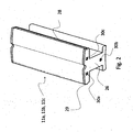
- FIG. 2 shows a perspective view of a stator 11a, 11b, 11c. Furthermore, the illustration shows the contact region 26 on which a further stator segment 11b or one or two end pieces 15a, 15b can be arranged. In the stator head oriented away from the center axis M of the motor, connecting elements 28, 29 are provided for establishing a connection between the stator teeth 2. Furthermore, the coupling elements are shown within the contact region 26.
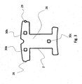
- FIG. 3 shows a front view of a stator tooth segment 11 a, 11 b, 11 c.
- the connecting elements 28, 29 and the coupling elements 30a, 30b, 30c which are used for establishing a connection between two stator tooth segments 11a, 11b, 11c or between stator tooth segments 11a, 11b, 11c and end pieces 15a, 15b, emerge .
- the number of coupling elements 30a, 30b, 30c can be increased or reduced as needed.
- the shape of these coupling elements 30a, 30b, 30c is not limited to the square variant shown but can also be configured in any other conceivable form.
- the connecting elements 28, 29 can be seen, which may be formed as a groove and recess.
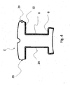
- FIG. 4 is a sectional view of a stator tooth 2 shown.
- the insulating layer 32 covers at least partially the first section 8, the second section 6 and the third section 10. It can be seen that the insulating layer 32 runs continuously and therefore has no gaps.
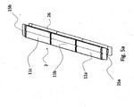
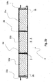
- FIG. 5a a stator tooth 2 composed of several parts can be seen.
- the stator tooth 2 is in this case of the segments 11 a, 11 b, 11 c and the two end pieces 15a, 15b put together. It is possible that only two stator segments 11a, 11b or more than three stator segments are joined together.
- FIG. 5b a side view of the previously described stator tooth 2 is shown.
- the contact region 26 is designed such that, for example, the segment 11 a on the segment 11 b and the segment 11 b can be arranged on the segment 11 c.
- the end pieces 15a and 15b are not configured identically, since the one end piece 15a engages the segment 11 a and the segment 11 c engages in the end piece 15b.
- an arrangement with identically designed end pieces 15a, 15b is also conceivable.
- FIG. 5c shows an enlarged section of the in FIG. 5b marked with X, in which a coupling element 30a is shown.
- coupling element 30a of the segment 11a engages in a depression of the element 11b.
- the point at which the coupling elements 30a, 30b, 30c are provided can be chosen arbitrarily, it is only important that the coupling elements 30a, 30b, 30c of different segments 11a, 11b, 11c and end pieces 15a, 15b are compatible with each other ,
- FIG. 6 shows an exploded view of a stator tooth 2.
- the stator tooth 2 in the variant shown from two end pieces 15a, 15b and three segments 11a, 11 b, 11c.
- the segments 11a, 11b, 11c in this case each have a first section 8, a second section 6 and a third section 10.
- the first portion 8 of all segments 11a, 11b, 11c forms a connection area between the end pieces 15a, 15b.
- a continuous insulation layer 32 is applied to both sections.
- the second portion 6 extends in the direction orthogonal to the longitudinal axis L beyond the Ver Strukturs Scheme.
- the part of the second section 6, which is covered in this transition region with a plastic layer, extends only over a fraction of the depth of the third section 10.
- the transition region of the first Region 8 to the third region 10 may be designed in accordance with the transition region from the first region to the second region.
- the projection of the third section 10 of the segments 11a, 11b, 11c on a plane is greater than the corresponding projection of the second section 6 on the plane.
- the electrically isolated part of the third portion extends in the direction orthogonal to the direction of the longitudinal axis L beyond the coated part of the second portion 6.
- the segments 11 a, 11 b, 11 c have coupling elements which are connected to one another by joining technology. It's from the FIG. 2 shown that the segment 11 b is disposed between the segments 11 a and 11 c and therefore has no contact with one of the end pieces 15 a, 15 b. Further, the cross section of the end pieces 15a, 15b of the segments 11 a, 11 b, 11 c correspond.
- the end pieces 15a, 15b furthermore have a grooved component section 22, which serves to guide the wire during winding of the coil.
- the end pieces 15a, 15b are made of a non-conductive material and the length of an end piece 15a, 15b corresponds to the fraction of the length of a segment 11a, 11b, 11c.
Landscapes
- Health & Medical Sciences (AREA)
- Engineering & Computer Science (AREA)
- Life Sciences & Earth Sciences (AREA)
- Animal Behavior & Ethology (AREA)
- Anesthesiology (AREA)
- Biomedical Technology (AREA)
- Heart & Thoracic Surgery (AREA)
- Hematology (AREA)
- Power Engineering (AREA)
- Vascular Medicine (AREA)
- General Health & Medical Sciences (AREA)
- Public Health (AREA)
- Veterinary Medicine (AREA)
- Iron Core Of Rotating Electric Machines (AREA)
- Insulation, Fastening Of Motor, Generator Windings (AREA)
- Manufacture Of Motors, Generators (AREA)
Claims (9)
- Moteur électrique comprenant au moins un stator et un rotor, le stator présentant au moins une dent de stator (2) et au moins une dent de stator (2) présentant au moins un premier et un deuxième bout (15a, 15b) ainsi qu'au moins un corps de liaison reliant les bouts (15a, 15b) entre le premier et le deuxième bout (15a, 15b), le corps de liaison étant réalisé en plusieurs parties et se composant d'au moins deux segments (11a, 11b), et le corps de liaison présentant au moins une première portion (8) en tant que surface de butée pour une partie d'une bobine,
caractérisé en ce que
des éléments d'accouplement (30a, 30b, 30c) sont prévus à l'intérieur des régions de contact (26) entre deux segments (11a, 11b) et entre un segment (11a, 11b) et un bout (15a, 15b), les bouts (15a, 15b) et la première portion (8) étant réalisés de manière électriquement isolante. - Moteur électrique selon la revendication 1, caractérisé en ce qu'au moins la première portion (8) est au moins en partie surmoulée de plastique.
- Moteur électrique selon au moins l'une quelconque des revendications précédentes, caractérisé en ce que les segments (11a, 11b) sont connectés les uns aux autres de manière indissociable.
- Moteur électrique selon au moins l'une quelconque des revendications précédentes, caractérisé en ce que chaque bout (15a, 15b) est connecté de manière indissociable à un segment (11a, 11b).
- Moteur électrique selon au moins l'une quelconque des revendications précédentes, caractérisé en ce que la première portion (8) présente une longueur (L) d'au moins 10 mm, de préférence de 50-90 mm, de préférence une longueur fonction d'un multiple de la longueur de l'aimant.
- Moteur électrique selon au moins l'une quelconque des revendications précédentes, caractérisé en ce que la première portion (8) présente une couche de plastique dont l'épaisseur est inférieure à 0,5 mm, de préférence inférieure à 0,4 mm, et particulièrement préférablement inférieure à 0,3 mm.
- Moteur électrique selon au moins l'une quelconque des revendications précédentes, caractérisé en ce qu'à l'intérieur des segments sont disposés des corps magnétisables.
- Moteur électrique selon au moins l'une quelconque des revendications précédentes, caractérisé en ce que la section transversale des bouts (15a, 15b) correspond à la section transversale des segments (11a, 11b).
- Procédé de fabrication d'une dent de stator (2) pour un moteur électrique selon l'une quelconque des revendications précédentes, dans lequel la dent de stator (2) présente une première portion (8) en tant que surface de butée pour une partie d'une bobine, dans lequel la première portion (8) est constituée d'au moins deux segments (11a, 11b) qui sont disposés dans la direction longitudinale (L) d'une dent de stator (2), les segments (11a, 11b) étant terminés par un premier (15a) et un deuxième (15b) bout dans la direction longitudinale (L),
caractérisé en ce que
des éléments d'accouplement (30a, 30b, 30c) sont prévus à l'intérieur des régions de contact (26) entre deux segments (11a, 11b) et entre un segment (11a, 11b) et un bout (15a, 15TV), les bouts (15a, 15) et la première portion (8) étant réalisés de manière électriquement isolante.
Applications Claiming Priority (2)
| Application Number | Priority Date | Filing Date | Title |
|---|---|---|---|
| DE102008057390A DE102008057390A1 (de) | 2008-11-14 | 2008-11-14 | Segmentierte Stator-/Rotorelemente von Elektromotoren |
| PCT/EP2009/008082 WO2010054824A1 (fr) | 2008-11-14 | 2009-11-13 | Éléments de stator/rotor segmentés pour moteurs électriques |
Publications (3)
| Publication Number | Publication Date |
|---|---|
| EP2356734A1 EP2356734A1 (fr) | 2011-08-17 |
| EP2356734B1 true EP2356734B1 (fr) | 2015-09-16 |
| EP2356734B2 EP2356734B2 (fr) | 2022-01-12 |
Family
ID=41667367
Family Applications (1)
| Application Number | Title | Priority Date | Filing Date |
|---|---|---|---|
| EP09765015.4A Not-in-force EP2356734B2 (fr) | 2008-11-14 | 2009-11-13 | Éléments de stator/rotor segmentés pour moteurs électriques |
Country Status (5)
| Country | Link |
|---|---|
| EP (1) | EP2356734B2 (fr) |
| JP (1) | JP5979875B2 (fr) |
| CN (1) | CN102224656B (fr) |
| DE (1) | DE102008057390A1 (fr) |
| WO (1) | WO2010054824A1 (fr) |
Cited By (2)
| Publication number | Priority date | Publication date | Assignee | Title |
|---|---|---|---|---|
| DE102021209415A1 (de) | 2021-08-26 | 2023-03-02 | Thyssenkrupp Ag | Rotor für eine elektrische Maschine, sowie Verfahren zu Herstellung eines Rotors |
| DE102022106874A1 (de) | 2022-03-23 | 2023-09-28 | Borgwarner Inc. | Reluktanzmaschine |
Families Citing this family (10)
| Publication number | Priority date | Publication date | Assignee | Title |
|---|---|---|---|---|
| DE102011017456B4 (de) * | 2011-04-18 | 2015-04-30 | Sew-Eurodrive Gmbh & Co Kg | Statorsegment für einen segmentiert ausgeführten Stator eines Elektromotors, Stator aus gleichartigen Statorsegmenten und Verfahren zum Herstellen eines Stators aus Statorsegmenten |
| BR102012016288B1 (pt) * | 2012-06-29 | 2020-12-01 | Embraco Indústria De Compressores E Soluções Em Refrigeração Ltda. | segmento laminar para estator segmentado de motor elétrico |
| GB2493658B (en) * | 2012-10-15 | 2015-05-20 | Protean Electric Ltd | A tooth for an electric motor or generator |
| DE102014000690A1 (de) * | 2014-01-17 | 2015-07-23 | Kienle + Spiess Gmbh | Ringförmiges Lamellenpaket aus Einzelzahnpaketen sowie Verfahren zur Herstellung eines Lamellenpaketes |
| WO2016101983A1 (fr) * | 2014-12-22 | 2016-06-30 | Arcelik Anonim Sirketi | Stator segmenté et son procédé de fabrication |
| DE102017201438A1 (de) | 2017-01-30 | 2018-08-02 | Thyssenkrupp Ag | Blechpaketscheibe mit einer Mehrzahl von Blechpaketscheibensegmenten sowie Rotor |
| DE102018211865A1 (de) | 2018-07-17 | 2020-01-23 | Thyssenkrupp Ag | Rotor für einen Elektromotor, Verfahren zur Herstellung eines Rotors, sowie Elektromotor |
| JP7151438B2 (ja) * | 2018-12-06 | 2022-10-12 | 三菱電機株式会社 | 固定子、この固定子を用いる回転電機、および固定子の製造方法 |
| CA3196541A1 (fr) | 2020-11-03 | 2022-05-12 | Max Meyer LIBEN | Moteur electrique a onduleur integre et systeme de refroidissement partage |
| DE102022120521A1 (de) | 2022-08-15 | 2024-02-15 | Hoffmann Gmbh | Baueinheit für eine elektrische Maschine sowie Verfahren und Werkzeugsystem zur Herstellung einer solchen Baueinheit |
Citations (14)
| Publication number | Priority date | Publication date | Assignee | Title |
|---|---|---|---|---|
| US3122667A (en) * | 1961-05-25 | 1964-02-25 | Gen Electric | Laminated magnetic core for use in an electric inductive device |
| DE3311852A1 (de) | 1983-03-31 | 1984-10-11 | Siemens AG, 1000 Berlin und 8000 München | Verfahren zur herstellung eines paketes aus geschichteten blechlamellen fuer elektrische maschinen und geraete |
| US4893041A (en) | 1988-10-27 | 1990-01-09 | Emerson Electric Co. | Stator end cap insulator assembly including an improved stator liner, stator liner retainer and shading element insulator |
| WO1998032211A1 (fr) | 1997-01-21 | 1998-07-23 | Siemens Westinghouse Power Corporation | Conception modulaire de noyau de stator et fabrication de celui-ci |
| US5918360A (en) * | 1985-11-12 | 1999-07-06 | General Electric Company | Method of fabricating a salient pole electronically commutated motor |
| US6265804B1 (en) * | 1998-09-08 | 2001-07-24 | Kabushiki Kaisha Toshiba | Electric motor with split stator core and method of making the same |
| EP1322022A1 (fr) | 2001-12-23 | 2003-06-25 | Grundfos A/S | Stator à construction modulaire |
| EP1528655A2 (fr) * | 2003-10-31 | 2005-05-04 | Nidec Shibaura Corporation | Moteur moulé |
| US20060028092A1 (en) | 2004-03-23 | 2006-02-09 | Weirong Wang | End cap for segmented stator |
| US20060232143A1 (en) | 2005-04-15 | 2006-10-19 | Delaware Capital Formation | Over molded stator |
| DE102005051506A1 (de) | 2005-10-26 | 2007-05-16 | Sew Eurodrive Gmbh & Co | Elektromotor und Verfahren zum Herstellen eines Elektromotors |
| DE102006009440A1 (de) * | 2006-03-01 | 2007-09-06 | Siemens Ag | Elektrische Maschine mit kunststoffummantelten Polzähnen und entsprechendes Verfahren |
| WO2008075506A2 (fr) * | 2006-12-21 | 2008-06-26 | Toyota Jidosha Kabushiki Kaisha | Stator de moteur et son procédé de fabrication |
| US20080256783A1 (en) | 2007-04-19 | 2008-10-23 | Alfermann Timothy J | Method for producing a stator assembly |
Family Cites Families (10)
| Publication number | Priority date | Publication date | Assignee | Title |
|---|---|---|---|---|
| DE1218599B (de) * | 1965-03-25 | 1966-06-08 | Waasner B | Durch Schweissnaehte zusammengehaltenes Blechpaket mit Pressplatten fuer elektrische Maschinen |
| EP1179881B1 (fr) * | 1997-05-26 | 2004-09-22 | Denso Corporation | Générateur à courant alternatif pour véhicules |
| GB2420231B (en) * | 2003-09-12 | 2006-08-02 | Bosch Gmbh Robert | Armature core for an electric motor |
| US20090026876A1 (en) * | 2003-12-18 | 2009-01-29 | Intelligent Electric Motor Solutions Pty Ltd | Hybrid construction electric machine |
| DE102004004664A1 (de) * | 2004-01-29 | 2005-09-01 | Sew-Eurodrive Gmbh & Co. Kg | Elektromotor |
| JP2005312219A (ja) * | 2004-04-22 | 2005-11-04 | Minebea Co Ltd | 三層絶縁塗膜構造を有するモータコア及びその製造方法 |
| DE102004051462A1 (de) * | 2004-10-22 | 2006-04-27 | Robert Bosch Gmbh | Verfahren zum Umspritzen eines Ankers für elektrische Maschinen |
| JP2007074847A (ja) * | 2005-09-08 | 2007-03-22 | Toyota Motor Corp | ステータコアの製造装置および圧粉磁心の製造装置 |
| JP2008048502A (ja) * | 2006-08-11 | 2008-02-28 | Jtekt Corp | 電動モータ |
| TW200824224A (en) * | 2006-11-17 | 2008-06-01 | Lidashi Industry Co Ltd | A stator structure |
-
2008
- 2008-11-14 DE DE102008057390A patent/DE102008057390A1/de not_active Withdrawn
-
2009
- 2009-11-13 EP EP09765015.4A patent/EP2356734B2/fr not_active Not-in-force
- 2009-11-13 CN CN200980145356.1A patent/CN102224656B/zh not_active Expired - Fee Related
- 2009-11-13 JP JP2011535921A patent/JP5979875B2/ja not_active Expired - Fee Related
- 2009-11-13 WO PCT/EP2009/008082 patent/WO2010054824A1/fr not_active Ceased
Patent Citations (14)
| Publication number | Priority date | Publication date | Assignee | Title |
|---|---|---|---|---|
| US3122667A (en) * | 1961-05-25 | 1964-02-25 | Gen Electric | Laminated magnetic core for use in an electric inductive device |
| DE3311852A1 (de) | 1983-03-31 | 1984-10-11 | Siemens AG, 1000 Berlin und 8000 München | Verfahren zur herstellung eines paketes aus geschichteten blechlamellen fuer elektrische maschinen und geraete |
| US5918360A (en) * | 1985-11-12 | 1999-07-06 | General Electric Company | Method of fabricating a salient pole electronically commutated motor |
| US4893041A (en) | 1988-10-27 | 1990-01-09 | Emerson Electric Co. | Stator end cap insulator assembly including an improved stator liner, stator liner retainer and shading element insulator |
| WO1998032211A1 (fr) | 1997-01-21 | 1998-07-23 | Siemens Westinghouse Power Corporation | Conception modulaire de noyau de stator et fabrication de celui-ci |
| US6265804B1 (en) * | 1998-09-08 | 2001-07-24 | Kabushiki Kaisha Toshiba | Electric motor with split stator core and method of making the same |
| EP1322022A1 (fr) | 2001-12-23 | 2003-06-25 | Grundfos A/S | Stator à construction modulaire |
| EP1528655A2 (fr) * | 2003-10-31 | 2005-05-04 | Nidec Shibaura Corporation | Moteur moulé |
| US20060028092A1 (en) | 2004-03-23 | 2006-02-09 | Weirong Wang | End cap for segmented stator |
| US20060232143A1 (en) | 2005-04-15 | 2006-10-19 | Delaware Capital Formation | Over molded stator |
| DE102005051506A1 (de) | 2005-10-26 | 2007-05-16 | Sew Eurodrive Gmbh & Co | Elektromotor und Verfahren zum Herstellen eines Elektromotors |
| DE102006009440A1 (de) * | 2006-03-01 | 2007-09-06 | Siemens Ag | Elektrische Maschine mit kunststoffummantelten Polzähnen und entsprechendes Verfahren |
| WO2008075506A2 (fr) * | 2006-12-21 | 2008-06-26 | Toyota Jidosha Kabushiki Kaisha | Stator de moteur et son procédé de fabrication |
| US20080256783A1 (en) | 2007-04-19 | 2008-10-23 | Alfermann Timothy J | Method for producing a stator assembly |
Cited By (3)
| Publication number | Priority date | Publication date | Assignee | Title |
|---|---|---|---|---|
| DE102021209415A1 (de) | 2021-08-26 | 2023-03-02 | Thyssenkrupp Ag | Rotor für eine elektrische Maschine, sowie Verfahren zu Herstellung eines Rotors |
| DE102022106874A1 (de) | 2022-03-23 | 2023-09-28 | Borgwarner Inc. | Reluktanzmaschine |
| US12470096B2 (en) | 2022-03-23 | 2025-11-11 | Borg Warner Inc. | Reluctance machine |
Also Published As
| Publication number | Publication date |
|---|---|
| CN102224656B (zh) | 2016-05-18 |
| DE102008057390A1 (de) | 2010-05-20 |
| WO2010054824A1 (fr) | 2010-05-20 |
| EP2356734A1 (fr) | 2011-08-17 |
| JP5979875B2 (ja) | 2016-08-31 |
| JP2012509048A (ja) | 2012-04-12 |
| CN102224656A (zh) | 2011-10-19 |
| EP2356734B2 (fr) | 2022-01-12 |
Similar Documents
| Publication | Publication Date | Title |
|---|---|---|
| EP2356734B1 (fr) | Éléments de stator/rotor segmentés pour moteurs électriques | |
| EP2688183B1 (fr) | Bobine électrique fabriquée selon une technique de coulage | |
| EP2647110B1 (fr) | Procédé de fabrication d'un enroulement de stator d'un moteur électrique, notamment d'un générateur de courant alternatif | |
| DE102008023923B4 (de) | Stator, Verfahren zur Herstellung von Statorsegmenten, Verfahren zur Herstellung von einem Stator | |
| EP2436102B1 (fr) | Procédé pour produire un enroulement de stator d'une machine électrique, notamment pour produire un alternateur | |
| DE102015216840A1 (de) | Stator mit isolierter Stabwicklung für eine elektrische Maschine | |
| DE102023102021A1 (de) | Verfahren zur Herstellung eines Stators und Stator | |
| EP3381107B1 (fr) | Tole electrique dotee d'une ame imprimee | |
| DE112004001898T5 (de) | Kurzschlußteil, Kommutator und Verfahren zur Herstellung eines Kurzschlußteils | |
| EP3357141B1 (fr) | Stator ou rotor, fabriqué selon un procédé de la technique d'insertion, d'une machine électrique avec une longueur de tôle raccourcie | |
| EP1423899A1 (fr) | Machine a ondes progressives | |
| EP3167540B1 (fr) | Procédé de fabrication d'une machine électrique comportant des bobines formées et machine électrique et outil de fabrication | |
| DE102014218224B4 (de) | Wicklungsträger, Elektromotor mit einem Wicklungsträger | |
| DE10059575A1 (de) | Elektrische Maschine und Stator für eine elektrische Maschine und Herstellungsverfahren dafür | |
| DE102017213106B4 (de) | Verfahren zur Herstellung einer elektrotechnischen Spule | |
| EP3772784B1 (fr) | Fiche à double rangée pour un câble plat ou film, procédé de fabrication d'une telle fiche et dispositif de transfert de courant | |
| EP0932241A2 (fr) | Procédé de fabrication de barres conductrices | |
| EP4568080A1 (fr) | Cage de rotor en court-circuit, ensemble rotor et procédé d'assemblage | |
| DE102023103204A1 (de) | Verfahren zum Herstellen eines Läufers und/oder Rotors sowie Läufer und/oder Rotor und elektrische Maschine | |
| DE102014200323A1 (de) | Spulensegmente für einen Elektromotor | |
| DE102020133307A1 (de) | Statoranordnung und Verfahren zu seiner Herstellung | |
| DE202019100406U1 (de) | Elektrische Maschine, vorgeformte Statorwicklungen | |
| DE102019116590A1 (de) | Elektrischer Leiter aus zwei metallischen Werkstoffen, Verfahren zur Herstellung und Verwendung |
Legal Events
| Date | Code | Title | Description |
|---|---|---|---|
| PUAI | Public reference made under article 153(3) epc to a published international application that has entered the european phase |
Free format text: ORIGINAL CODE: 0009012 |
|
| 17P | Request for examination filed |
Effective date: 20110614 |
|
| AK | Designated contracting states |
Kind code of ref document: A1 Designated state(s): AT BE BG CH CY CZ DE DK EE ES FI FR GB GR HR HU IE IS IT LI LT LU LV MC MK MT NL NO PL PT RO SE SI SK SM TR |
|
| RIN1 | Information on inventor provided before grant (corrected) |
Inventor name: HACK, ARNO Inventor name: BORNER, RUDOLF |
|
| DAX | Request for extension of the european patent (deleted) | ||
| 17Q | First examination report despatched |
Effective date: 20140219 |
|
| GRAP | Despatch of communication of intention to grant a patent |
Free format text: ORIGINAL CODE: EPIDOSNIGR1 |
|
| INTG | Intention to grant announced |
Effective date: 20150625 |
|
| GRAS | Grant fee paid |
Free format text: ORIGINAL CODE: EPIDOSNIGR3 |
|
| GRAA | (expected) grant |
Free format text: ORIGINAL CODE: 0009210 |
|
| AK | Designated contracting states |
Kind code of ref document: B1 Designated state(s): AT BE BG CH CY CZ DE DK EE ES FI FR GB GR HR HU IE IS IT LI LT LU LV MC MK MT NL NO PL PT RO SE SI SK SM TR |
|
| REG | Reference to a national code |
Ref country code: GB Ref legal event code: FG4D Free format text: NOT ENGLISH |
|
| REG | Reference to a national code |
Ref country code: CH Ref legal event code: EP |
|
| REG | Reference to a national code |
Ref country code: IE Ref legal event code: FG4D Free format text: LANGUAGE OF EP DOCUMENT: GERMAN |
|
| REG | Reference to a national code |
Ref country code: AT Ref legal event code: REF Ref document number: 750491 Country of ref document: AT Kind code of ref document: T Effective date: 20151015 |
|
| REG | Reference to a national code |
Ref country code: DE Ref legal event code: R096 Ref document number: 502009011597 Country of ref document: DE |
|
| REG | Reference to a national code |
Ref country code: FR Ref legal event code: PLFP Year of fee payment: 7 |
|
| REG | Reference to a national code |
Ref country code: NL Ref legal event code: MP Effective date: 20150916 |
|
| PG25 | Lapsed in a contracting state [announced via postgrant information from national office to epo] |
Ref country code: NO Free format text: LAPSE BECAUSE OF FAILURE TO SUBMIT A TRANSLATION OF THE DESCRIPTION OR TO PAY THE FEE WITHIN THE PRESCRIBED TIME-LIMIT Effective date: 20151216 Ref country code: LT Free format text: LAPSE BECAUSE OF FAILURE TO SUBMIT A TRANSLATION OF THE DESCRIPTION OR TO PAY THE FEE WITHIN THE PRESCRIBED TIME-LIMIT Effective date: 20150916 Ref country code: GR Free format text: LAPSE BECAUSE OF FAILURE TO SUBMIT A TRANSLATION OF THE DESCRIPTION OR TO PAY THE FEE WITHIN THE PRESCRIBED TIME-LIMIT Effective date: 20151217 Ref country code: LV Free format text: LAPSE BECAUSE OF FAILURE TO SUBMIT A TRANSLATION OF THE DESCRIPTION OR TO PAY THE FEE WITHIN THE PRESCRIBED TIME-LIMIT Effective date: 20150916 Ref country code: FI Free format text: LAPSE BECAUSE OF FAILURE TO SUBMIT A TRANSLATION OF THE DESCRIPTION OR TO PAY THE FEE WITHIN THE PRESCRIBED TIME-LIMIT Effective date: 20150916 |
|
| REG | Reference to a national code |
Ref country code: LT Ref legal event code: MG4D |
|
| PG25 | Lapsed in a contracting state [announced via postgrant information from national office to epo] |
Ref country code: SE Free format text: LAPSE BECAUSE OF FAILURE TO SUBMIT A TRANSLATION OF THE DESCRIPTION OR TO PAY THE FEE WITHIN THE PRESCRIBED TIME-LIMIT Effective date: 20150916 Ref country code: HR Free format text: LAPSE BECAUSE OF FAILURE TO SUBMIT A TRANSLATION OF THE DESCRIPTION OR TO PAY THE FEE WITHIN THE PRESCRIBED TIME-LIMIT Effective date: 20150916 |
|
| PG25 | Lapsed in a contracting state [announced via postgrant information from national office to epo] |
Ref country code: NL Free format text: LAPSE BECAUSE OF FAILURE TO SUBMIT A TRANSLATION OF THE DESCRIPTION OR TO PAY THE FEE WITHIN THE PRESCRIBED TIME-LIMIT Effective date: 20150916 |
|
| PG25 | Lapsed in a contracting state [announced via postgrant information from national office to epo] |
Ref country code: CZ Free format text: LAPSE BECAUSE OF FAILURE TO SUBMIT A TRANSLATION OF THE DESCRIPTION OR TO PAY THE FEE WITHIN THE PRESCRIBED TIME-LIMIT Effective date: 20150916 Ref country code: ES Free format text: LAPSE BECAUSE OF FAILURE TO SUBMIT A TRANSLATION OF THE DESCRIPTION OR TO PAY THE FEE WITHIN THE PRESCRIBED TIME-LIMIT Effective date: 20150916 Ref country code: EE Free format text: LAPSE BECAUSE OF FAILURE TO SUBMIT A TRANSLATION OF THE DESCRIPTION OR TO PAY THE FEE WITHIN THE PRESCRIBED TIME-LIMIT Effective date: 20150916 Ref country code: SK Free format text: LAPSE BECAUSE OF FAILURE TO SUBMIT A TRANSLATION OF THE DESCRIPTION OR TO PAY THE FEE WITHIN THE PRESCRIBED TIME-LIMIT Effective date: 20150916 Ref country code: IS Free format text: LAPSE BECAUSE OF FAILURE TO SUBMIT A TRANSLATION OF THE DESCRIPTION OR TO PAY THE FEE WITHIN THE PRESCRIBED TIME-LIMIT Effective date: 20160116 |
|
| PG25 | Lapsed in a contracting state [announced via postgrant information from national office to epo] |
Ref country code: RO Free format text: LAPSE BECAUSE OF FAILURE TO SUBMIT A TRANSLATION OF THE DESCRIPTION OR TO PAY THE FEE WITHIN THE PRESCRIBED TIME-LIMIT Effective date: 20150916 Ref country code: PL Free format text: LAPSE BECAUSE OF FAILURE TO SUBMIT A TRANSLATION OF THE DESCRIPTION OR TO PAY THE FEE WITHIN THE PRESCRIBED TIME-LIMIT Effective date: 20150916 Ref country code: PT Free format text: LAPSE BECAUSE OF FAILURE TO SUBMIT A TRANSLATION OF THE DESCRIPTION OR TO PAY THE FEE WITHIN THE PRESCRIBED TIME-LIMIT Effective date: 20160118 |
|
| REG | Reference to a national code |
Ref country code: DE Ref legal event code: R026 Ref document number: 502009011597 Country of ref document: DE |
|
| PLBI | Opposition filed |
Free format text: ORIGINAL CODE: 0009260 |
|
| PG25 | Lapsed in a contracting state [announced via postgrant information from national office to epo] |
Ref country code: MC Free format text: LAPSE BECAUSE OF FAILURE TO SUBMIT A TRANSLATION OF THE DESCRIPTION OR TO PAY THE FEE WITHIN THE PRESCRIBED TIME-LIMIT Effective date: 20150916 Ref country code: LU Free format text: LAPSE BECAUSE OF FAILURE TO SUBMIT A TRANSLATION OF THE DESCRIPTION OR TO PAY THE FEE WITHIN THE PRESCRIBED TIME-LIMIT Effective date: 20151113 |
|
| REG | Reference to a national code |
Ref country code: CH Ref legal event code: PL |
|
| PLAX | Notice of opposition and request to file observation + time limit sent |
Free format text: ORIGINAL CODE: EPIDOSNOBS2 |
|
| 26 | Opposition filed |
Opponent name: SEW-EURODRIVE GMBH & CO. KG Effective date: 20160610 |
|
| PG25 | Lapsed in a contracting state [announced via postgrant information from national office to epo] |
Ref country code: CH Free format text: LAPSE BECAUSE OF NON-PAYMENT OF DUE FEES Effective date: 20151130 Ref country code: LI Free format text: LAPSE BECAUSE OF NON-PAYMENT OF DUE FEES Effective date: 20151130 |
|
| REG | Reference to a national code |
Ref country code: IE Ref legal event code: MM4A |
|
| PG25 | Lapsed in a contracting state [announced via postgrant information from national office to epo] |
Ref country code: DK Free format text: LAPSE BECAUSE OF FAILURE TO SUBMIT A TRANSLATION OF THE DESCRIPTION OR TO PAY THE FEE WITHIN THE PRESCRIBED TIME-LIMIT Effective date: 20150916 |
|
| PG25 | Lapsed in a contracting state [announced via postgrant information from national office to epo] |
Ref country code: IE Free format text: LAPSE BECAUSE OF NON-PAYMENT OF DUE FEES Effective date: 20151113 |
|
| REG | Reference to a national code |
Ref country code: FR Ref legal event code: PLFP Year of fee payment: 8 |
|
| PLBB | Reply of patent proprietor to notice(s) of opposition received |
Free format text: ORIGINAL CODE: EPIDOSNOBS3 |
|
| PG25 | Lapsed in a contracting state [announced via postgrant information from national office to epo] |
Ref country code: SI Free format text: LAPSE BECAUSE OF FAILURE TO SUBMIT A TRANSLATION OF THE DESCRIPTION OR TO PAY THE FEE WITHIN THE PRESCRIBED TIME-LIMIT Effective date: 20150916 |
|
| REG | Reference to a national code |
Ref country code: AT Ref legal event code: MM01 Ref document number: 750491 Country of ref document: AT Kind code of ref document: T Effective date: 20151113 |
|
| PG25 | Lapsed in a contracting state [announced via postgrant information from national office to epo] |
Ref country code: AT Free format text: LAPSE BECAUSE OF NON-PAYMENT OF DUE FEES Effective date: 20151113 |
|
| PG25 | Lapsed in a contracting state [announced via postgrant information from national office to epo] |
Ref country code: SM Free format text: LAPSE BECAUSE OF FAILURE TO SUBMIT A TRANSLATION OF THE DESCRIPTION OR TO PAY THE FEE WITHIN THE PRESCRIBED TIME-LIMIT Effective date: 20150916 Ref country code: HU Free format text: LAPSE BECAUSE OF FAILURE TO SUBMIT A TRANSLATION OF THE DESCRIPTION OR TO PAY THE FEE WITHIN THE PRESCRIBED TIME-LIMIT; INVALID AB INITIO Effective date: 20091113 Ref country code: BG Free format text: LAPSE BECAUSE OF FAILURE TO SUBMIT A TRANSLATION OF THE DESCRIPTION OR TO PAY THE FEE WITHIN THE PRESCRIBED TIME-LIMIT Effective date: 20150916 |
|
| PG25 | Lapsed in a contracting state [announced via postgrant information from national office to epo] |
Ref country code: CY Free format text: LAPSE BECAUSE OF FAILURE TO SUBMIT A TRANSLATION OF THE DESCRIPTION OR TO PAY THE FEE WITHIN THE PRESCRIBED TIME-LIMIT Effective date: 20150916 |
|
| PG25 | Lapsed in a contracting state [announced via postgrant information from national office to epo] |
Ref country code: BE Free format text: LAPSE BECAUSE OF NON-PAYMENT OF DUE FEES Effective date: 20151130 |
|
| PG25 | Lapsed in a contracting state [announced via postgrant information from national office to epo] |
Ref country code: TR Free format text: LAPSE BECAUSE OF FAILURE TO SUBMIT A TRANSLATION OF THE DESCRIPTION OR TO PAY THE FEE WITHIN THE PRESCRIBED TIME-LIMIT Effective date: 20150916 Ref country code: MT Free format text: LAPSE BECAUSE OF FAILURE TO SUBMIT A TRANSLATION OF THE DESCRIPTION OR TO PAY THE FEE WITHIN THE PRESCRIBED TIME-LIMIT Effective date: 20150916 |
|
| REG | Reference to a national code |
Ref country code: FR Ref legal event code: PLFP Year of fee payment: 9 |
|
| APAH | Appeal reference modified |
Free format text: ORIGINAL CODE: EPIDOSCREFNO |
|
| APBM | Appeal reference recorded |
Free format text: ORIGINAL CODE: EPIDOSNREFNO |
|
| APBP | Date of receipt of notice of appeal recorded |
Free format text: ORIGINAL CODE: EPIDOSNNOA2O |
|
| APBQ | Date of receipt of statement of grounds of appeal recorded |
Free format text: ORIGINAL CODE: EPIDOSNNOA3O |
|
| PG25 | Lapsed in a contracting state [announced via postgrant information from national office to epo] |
Ref country code: MK Free format text: LAPSE BECAUSE OF FAILURE TO SUBMIT A TRANSLATION OF THE DESCRIPTION OR TO PAY THE FEE WITHIN THE PRESCRIBED TIME-LIMIT Effective date: 20150916 |
|
| PGFP | Annual fee paid to national office [announced via postgrant information from national office to epo] |
Ref country code: FR Payment date: 20191121 Year of fee payment: 11 |
|
| RAP2 | Party data changed (patent owner data changed or rights of a patent transferred) |
Owner name: ROBERT BOSCH GMBH |
|
| PGFP | Annual fee paid to national office [announced via postgrant information from national office to epo] |
Ref country code: GB Payment date: 20191126 Year of fee payment: 11 |
|
| APBU | Appeal procedure closed |
Free format text: ORIGINAL CODE: EPIDOSNNOA9O |
|
| GBPC | Gb: european patent ceased through non-payment of renewal fee |
Effective date: 20201113 |
|
| PG25 | Lapsed in a contracting state [announced via postgrant information from national office to epo] |
Ref country code: FR Free format text: LAPSE BECAUSE OF NON-PAYMENT OF DUE FEES Effective date: 20201130 |
|
| PG25 | Lapsed in a contracting state [announced via postgrant information from national office to epo] |
Ref country code: GB Free format text: LAPSE BECAUSE OF NON-PAYMENT OF DUE FEES Effective date: 20201113 |
|
| PUAH | Patent maintained in amended form |
Free format text: ORIGINAL CODE: 0009272 |
|
| STAA | Information on the status of an ep patent application or granted ep patent |
Free format text: STATUS: PATENT MAINTAINED AS AMENDED |
|
| 27A | Patent maintained in amended form |
Effective date: 20220112 |
|
| AK | Designated contracting states |
Kind code of ref document: B2 Designated state(s): AT BE BG CH CY CZ DE DK EE ES FI FR GB GR HR HU IE IS IT LI LT LU LV MC MK MT NL NO PL PT RO SE SI SK SM TR |
|
| REG | Reference to a national code |
Ref country code: DE Ref legal event code: R102 Ref document number: 502009011597 Country of ref document: DE |
|
| PGFP | Annual fee paid to national office [announced via postgrant information from national office to epo] |
Ref country code: IT Payment date: 20221130 Year of fee payment: 14 |
|
| PGFP | Annual fee paid to national office [announced via postgrant information from national office to epo] |
Ref country code: DE Payment date: 20230124 Year of fee payment: 14 |
|
| REG | Reference to a national code |
Ref country code: DE Ref legal event code: R119 Ref document number: 502009011597 Country of ref document: DE |
|
| PG25 | Lapsed in a contracting state [announced via postgrant information from national office to epo] |
Ref country code: DE Free format text: LAPSE BECAUSE OF NON-PAYMENT OF DUE FEES Effective date: 20240601 |
|
| PG25 | Lapsed in a contracting state [announced via postgrant information from national office to epo] |
Ref country code: DE Free format text: LAPSE BECAUSE OF NON-PAYMENT OF DUE FEES Effective date: 20240601 |
|
| PG25 | Lapsed in a contracting state [announced via postgrant information from national office to epo] |
Ref country code: IT Free format text: LAPSE BECAUSE OF NON-PAYMENT OF DUE FEES Effective date: 20231113 |
|
| PG25 | Lapsed in a contracting state [announced via postgrant information from national office to epo] |
Ref country code: IT Free format text: LAPSE BECAUSE OF NON-PAYMENT OF DUE FEES Effective date: 20231113 |