EP1739744A2 - Wärmestrahlungsteil und Herstellungsverfahren - Google Patents
Wärmestrahlungsteil und Herstellungsverfahren Download PDFInfo
- Publication number
- EP1739744A2 EP1739744A2 EP06253356A EP06253356A EP1739744A2 EP 1739744 A2 EP1739744 A2 EP 1739744A2 EP 06253356 A EP06253356 A EP 06253356A EP 06253356 A EP06253356 A EP 06253356A EP 1739744 A2 EP1739744 A2 EP 1739744A2
- Authority
- EP
- European Patent Office
- Prior art keywords
- thermally conductive
- conductive polymer
- polymer layer
- layer
- heat radiation
- Prior art date
- Legal status (The legal status is an assumption and is not a legal conclusion. Google has not performed a legal analysis and makes no representation as to the accuracy of the status listed.)
- Withdrawn
Links
Images

Classifications
-
- H—ELECTRICITY
- H05—ELECTRIC TECHNIQUES NOT OTHERWISE PROVIDED FOR
- H05K—PRINTED CIRCUITS; CASINGS OR CONSTRUCTIONAL DETAILS OF ELECTRIC APPARATUS; MANUFACTURE OF ASSEMBLAGES OF ELECTRICAL COMPONENTS
- H05K7/00—Constructional details common to different types of electric apparatus
- H05K7/20—Modifications to facilitate cooling, ventilating, or heating
-
- H—ELECTRICITY
- H10—SEMICONDUCTOR DEVICES; ELECTRIC SOLID-STATE DEVICES NOT OTHERWISE PROVIDED FOR
- H10W—GENERIC PACKAGES, INTERCONNECTIONS, CONNECTORS OR OTHER CONSTRUCTIONAL DETAILS OF DEVICES COVERED BY CLASS H10
- H10W40/00—Arrangements for thermal protection or thermal control
- H10W40/20—Arrangements for cooling
- H10W40/25—Arrangements for cooling characterised by their materials
- H10W40/257—Arrangements for cooling characterised by their materials having a heterogeneous or anisotropic structure, e.g. powder or fibres in a matrix, wire mesh or porous structures
-
- H—ELECTRICITY
- H10—SEMICONDUCTOR DEVICES; ELECTRIC SOLID-STATE DEVICES NOT OTHERWISE PROVIDED FOR
- H10W—GENERIC PACKAGES, INTERCONNECTIONS, CONNECTORS OR OTHER CONSTRUCTIONAL DETAILS OF DEVICES COVERED BY CLASS H10
- H10W40/00—Arrangements for thermal protection or thermal control
- H10W40/20—Arrangements for cooling
- H10W40/25—Arrangements for cooling characterised by their materials
- H10W40/251—Organics
-
- H—ELECTRICITY
- H10—SEMICONDUCTOR DEVICES; ELECTRIC SOLID-STATE DEVICES NOT OTHERWISE PROVIDED FOR
- H10W—GENERIC PACKAGES, INTERCONNECTIONS, CONNECTORS OR OTHER CONSTRUCTIONAL DETAILS OF DEVICES COVERED BY CLASS H10
- H10W40/00—Arrangements for thermal protection or thermal control
- H10W40/20—Arrangements for cooling
- H10W40/25—Arrangements for cooling characterised by their materials
- H10W40/255—Arrangements for cooling characterised by their materials having a laminate or multilayered structure, e.g. direct bond copper [DBC] ceramic substrates
-
- H—ELECTRICITY
- H10—SEMICONDUCTOR DEVICES; ELECTRIC SOLID-STATE DEVICES NOT OTHERWISE PROVIDED FOR
- H10W—GENERIC PACKAGES, INTERCONNECTIONS, CONNECTORS OR OTHER CONSTRUCTIONAL DETAILS OF DEVICES COVERED BY CLASS H10
- H10W72/00—Interconnections or connectors in packages
- H10W72/30—Die-attach connectors
- H10W72/321—Structures or relative sizes of die-attach connectors
- H10W72/325—Die-attach connectors having a filler embedded in a matrix
-
- H—ELECTRICITY
- H10—SEMICONDUCTOR DEVICES; ELECTRIC SOLID-STATE DEVICES NOT OTHERWISE PROVIDED FOR
- H10W—GENERIC PACKAGES, INTERCONNECTIONS, CONNECTORS OR OTHER CONSTRUCTIONAL DETAILS OF DEVICES COVERED BY CLASS H10
- H10W72/00—Interconnections or connectors in packages
- H10W72/30—Die-attach connectors
- H10W72/351—Materials of die-attach connectors
-
- H—ELECTRICITY
- H10—SEMICONDUCTOR DEVICES; ELECTRIC SOLID-STATE DEVICES NOT OTHERWISE PROVIDED FOR
- H10W—GENERIC PACKAGES, INTERCONNECTIONS, CONNECTORS OR OTHER CONSTRUCTIONAL DETAILS OF DEVICES COVERED BY CLASS H10
- H10W72/00—Interconnections or connectors in packages
- H10W72/30—Die-attach connectors
- H10W72/351—Materials of die-attach connectors
- H10W72/353—Materials of die-attach connectors not comprising solid metals or solid metalloids, e.g. ceramics
-
- H—ELECTRICITY
- H10—SEMICONDUCTOR DEVICES; ELECTRIC SOLID-STATE DEVICES NOT OTHERWISE PROVIDED FOR
- H10W—GENERIC PACKAGES, INTERCONNECTIONS, CONNECTORS OR OTHER CONSTRUCTIONAL DETAILS OF DEVICES COVERED BY CLASS H10
- H10W72/00—Interconnections or connectors in packages
- H10W72/30—Die-attach connectors
- H10W72/351—Materials of die-attach connectors
- H10W72/353—Materials of die-attach connectors not comprising solid metals or solid metalloids, e.g. ceramics
- H10W72/354—Materials of die-attach connectors not comprising solid metals or solid metalloids, e.g. ceramics comprising polymers
-
- H—ELECTRICITY
- H10—SEMICONDUCTOR DEVICES; ELECTRIC SOLID-STATE DEVICES NOT OTHERWISE PROVIDED FOR
- H10W—GENERIC PACKAGES, INTERCONNECTIONS, CONNECTORS OR OTHER CONSTRUCTIONAL DETAILS OF DEVICES COVERED BY CLASS H10
- H10W90/00—Package configurations
- H10W90/701—Package configurations characterised by the relative positions of pads or connectors relative to package parts
- H10W90/731—Package configurations characterised by the relative positions of pads or connectors relative to package parts of die-attach connectors
- H10W90/734—Package configurations characterised by the relative positions of pads or connectors relative to package parts of die-attach connectors between a chip and a stacked insulating package substrate, interposer or RDL
-
- H—ELECTRICITY
- H10—SEMICONDUCTOR DEVICES; ELECTRIC SOLID-STATE DEVICES NOT OTHERWISE PROVIDED FOR
- H10W—GENERIC PACKAGES, INTERCONNECTIONS, CONNECTORS OR OTHER CONSTRUCTIONAL DETAILS OF DEVICES COVERED BY CLASS H10
- H10W90/00—Package configurations
- H10W90/701—Package configurations characterised by the relative positions of pads or connectors relative to package parts
- H10W90/731—Package configurations characterised by the relative positions of pads or connectors relative to package parts of die-attach connectors
- H10W90/736—Package configurations characterised by the relative positions of pads or connectors relative to package parts of die-attach connectors between a chip and a stacked lead frame, conducting package substrate or heat sink
Definitions
- the present invention relates to a heat radiation member for radiating heat generated from semiconductor devices and electronic parts, and to a production method for the same.
- a thermal diffusion sheet made of graphite or metal cannot be placed in direct contact with exothermic parts with satisfactory adhesion therebetween, because the graphite sheet or metal sheet has poor conformity to the exothermic parts due to high stiffness thereof. As a result, the expected effect of excellent thermal conduction properties of the sheet may not be obtained. Therefore, there is proposed a heat radiation member including a flexible sheet made of a thermally conductive polymer material, which is formed on at least one side of a thermal diffusion sheet such as a graphite sheet or a metal sheet having high stiffness.
- Japanese Laid-Open Patent Publications No.2003-168882 and No.2005-57088 each disclose a double-layer or triple-layer thermally conductive sheet including a soft thermally conductive layer which is formed on at least one side of a graphite sheet or the like.
- Japanese Laid-Open Patent Publication No.2004-243650 discloses a thermally conductive sheet including a thermally conductive silicone elastomer layer which is formed on a graphite sheet through a specific polymer layer to improve tackiness, adhesion, and repairability.
- Japanese Laid-Open Patent Publication No.11-340673 discloses a similar thermally conductive electromagnetic shield sheet provided with electromagnetic shielding properties.
- Japanese Laid-Open Patent Publication No.2003-158393 proposes a heat radiation structure including a specific phase changing thermally conductive material layer formed on a graphite sheet, in which said layer softens or melts at high temperature.
- the thermally conductive material layer made of a phase changing material handling ease in actual use is unsatisfactory as compared with a conventional solid thermally conductive material layer made of an elastomer-based material.
- the thermally conductive material layer made of a phase changing material softens or melts when it is exposed to high temperature, the thermally conductive layer may shrink and dislocate with respect to exothermic parts. This may reduce thermal conductivity of the layer.
- the thermally conductive material made of a phase changing material softens or melts to adhere to the exothermic parts. Therefore, the thermally conductive material made of the phase changing material has poor repairability.
- the term of "repairability" refers to a property of being able to be detached from the exothermic parts and relocated for correcting dislocation/mislocation. Therefore, the application field for such thermally conductive layers is limited to a narrow range.
- a heat radiation member is strongly desired, which can effectively transmit the heat from semiconductor devices and electronic parts to a thermal diffusion sheet, and has excellent handling ease at the time of mounting, as well as high repairability and sufficient adhesion with the heat radiation part and exothermic parts for preventing dislocation with respect to them.
- the present invention has been made in view of the above-mentioned problems. It is an object of the present invention to provide a heat radiation member for effectively transmitting and diffusing heat from exothermic parts mounted on electronic equipment, and a production method for the same.
- the present invention provides a heat radiation member including a thermal diffusion sheet and a thermally conductive polymer layer provided on at least a part of the thermal diffusion sheet.
- Thermal conductivity of the thermally conductive polymer layer in a thickness direction of the layer is higher than thermal conductivity of the thermally conductive polymer layer in a direction parallel to the surface of the layer.
- the present invention also provides a method for producing a heat radiation member including a thermal diffusion sheet and a thermally conductive polymer layer provided on at least a part of the thermal diffusion sheet.
- the method includes steps of independently forming the thermally conductive layer in a sheet from a thermally conductive polymer composition containing a thermal conductive filler, wherein the thermal conductive filler in the layer is oriented in a specific direction such that thermal conductivity of the thermally conductive polymer layer in a thickness direction of the layer becomes higher than thermal conductivity of the thermally conductive polymer layer in a direction parallel to the surface of the layer; and joining the formed thermally conductive layer onto at least a part of the thermal diffusion sheet.
- the method includes steps of placing a thermally conductive polymer composition containing a thermal conductive filler onto at least a part of the thermal diffusion sheet; orienting the thermally conductive filler in a specific direction such that thermal conductivity of the thermally conductive polymer layer to be obtained in a thickness direction of the layer becomes higher than thermal conductivity of the thermally conductive polymer layer in a direction parallel to the surface of the layer; and curing the thermally conductive polymer composition, while the orientation of the thermally conductive filler is maintained, to form the thermally conductive layer on the thermal diffusion sheet.
- FIG. 1 shows a perspective view of a heat radiation member 10 according to the first embodiment.
- the heat radiation member 10 includes a thermal diffusion sheet 1 and thermally conductive polymer layers 2 formed on parts of a top surface of the thermal diffusion sheet 1.
- the thermally conductive polymer layers 2 are selectively formed on the thermal diffusion sheet 1. at positions corresponding to exothermic parts which generate heat when in use.
- the thermal diffusion sheet 1 is preferably a graphite sheet.
- Fig. 2 shows a sectional view of the thermally conductive polymer layer 2.
- the thermally conductive polymer layer 2 contains a polymer material 5 as a matrix and carbon fibers 3 as a thermally conductive filler.
- the carbon fibers 3 are oriented in such a manner that the longitudinal axes of the fibers are aligned along the thickness direction of the thermally conductive polymer layer 2, namely in the Z axis direction shown in Fig. 2. Accordingly, the longitudinal axes of the carbon fibers 3 are substantially perpendicular to the thermal diffusion sheet 1.
- the carbon fibers 3 have a higher thermal conductivity in the longitudinal axial direction than in the radial direction of the fibers.
- the thermal conductivity of the thermally conductive polymer layer 2 in the thickness direction is set higher than the thermal conductivity of the layer in a direction parallel to the surface thereof.
- the orientation of the carbon fibers 3 is preferably carried out by an application of a magnetic field thereto.
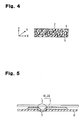
- Fig. 5 shows that the heat radiation member 10 is mounted on a printed circuit board 6 having exothermic parts 7 such as semiconductor packages.
- the heat radiation member 10 is placed on the printed circuit board 6 in such a manner that the thermally conductive polymer layers 2 come into close contact with the exothermic parts 7.
- the heat generated from the exothermic parts 7 is effectively transmitted to the thermal diffusion sheet 1 through the thermally conductive polymer layers 2, diffused into the thermal diffusion sheet 1 in a direction parallel to the surface of the sheet, and further radiated to the outside of the sheet from the periphery and surface of the thermal diffusion sheet 1.
- the thermal conductivity of the thermally conductive polymer layer 2 in the thickness direction is higher than the thermal conductivity of the layer in a direction parallel to the surface thereof.
- the direction of the conduction of the heat from the exothermic parts 7 corresponds to the thickness direction of the thermally conductive polymer layers 2. Therefore, the thermally conductive polymer layers 2 can rapidly and efficiently conduct the heat from the exothermic parts 7 to the thermal diffusion sheet 1.
- the carbon fibers 3 having higher thermal conductivity in the longitudinal axial direction than in the radial direction of the fibers is used as the thermally conductive filler. Since orientation of the carbon fibers 3 can be easily controlled by application of a magnetic field thereto due to their magnetic anisotropy, the carbon fibers 3 can be highly oriented in such a manner that the longitudinal axes of the carbon fibers 3 are aligned along the thickness direction of the thermally conductive polymer layer 2. As a result, the thermal conductivity in the thickness direction of the thermally conductive polymer layer 2 can be significantly improved.
- the heat characteristics of the thermally conductive polymer layer 2 can be greatly improved by using carbon fibers 3 that have been oriented, as compared with when the same carbon fibers 3 is used without being oriented. As a result, an excellent heat radiation member can be obtained at a low material cost.
- a graphite sheet may be used as the thermal diffusion sheet 1 in the first embodiment.
- such a thermal diffusion sheet 1 can diffuse the heat in a direction parallel to the surface more rapidly than in the thickness direction, because the graphite sheet has an extremely high thermal conductivity (100 to 800 W/mK) in a direction parallel to the surface than in the thickness direction of the sheet. Accordingly, the thermal diffusion sheet 1 made of a graphite sheet can diffuse the heat transmitted from the thermally conductive polymer layers 2 along the sheet more effectively.
- the heat radiation member 20 shown in Fig. 3 includes the thermal diffusion sheet 1 and the thermally conductive polymer layers 2 formed on the thermal diffusion sheet 1.
- the thermally conductive polymer layers 2 are selectively formed on the thermal diffusion sheet 1 at least at positions corresponding to exothermic parts that generate heat when in use.
- the thermal diffusion sheet 1 is preferably a composite sheet consisting of a graphite sheet 1b and aluminum foils 1a and 1c formed on the entire both sides of the graphite sheet 1b.
- Fig. 4 shows a sectional view of the thermally conductive polymer layer 2.
- the thermally conductive polymer layer 2 includes the polymer material 5 as a matrix and hexagonal boron nitride powders 4, which is in the form of scales, as a thermally conductive filler.
- the scaly hexagonal boron nitride powders 4 are oriented in such a manner that a direction along the surface of each scale (i.e. a direction substantially parallel to the surface of the scales) corresponds to the thickness direction of the thermally conductive polymer layer 2 as shown in Fig. 4. Accordingly, the direction parallel to the surface of each scale is substantially perpendicular to the surface of the thermal diffusion sheet 1.
- the scaly hexagonal boron nitride powders have a higher thermal conductivity in a direction parallel to the surface than in the thickness direction of each scale. More specifically, in the scaly hexagonal boron nitride powders, hexagonal boron nitride crystals are regularly oriented in a specific direction in general. When the hexagonal crystal structure is regarded as a hexagonal pillar, the direction parallel to the surface of the scales consists with a direction parallel to the cross section of the hexagonal pillar. The hexagonal boron nitride crystals have more excellent thermal conduction properties in a cross-sectional direction of the hexagonal pillar.
- the thermal conductivity of the thermally conductive polymer layer 2 in the thickness direction is set to be higher than the thermal conductivity in a direction parallel to the surface of the layer.
- the orientation of the hexagonal boron nitride powders 4 is preferably carried out by an application of a magnetic field thereto.
- the heat radiation member 20 of the second embodiment is mounted on the printed circuit board 6 in such a manner that the thermally conductive polymer layers 2 come in close contact with the exothermic parts 7 as shown in Fig. 5 as in the first embodiment. As a result, the heat generated from the exothermic parts 7 is transmitted to the thermal diffusion sheet 1 through the thermally conductive polymer layers 2 and effectively diffused along the thermal diffusion sheet 1.
- the heat radiation member 20 according to the second embodiment has the following advantages in addition to those of the first embodiment above-described.
- the scaly hexagonal boron nitride powders 4 are used as the thermally conductive filler.
- the orientation of the scaly hexagonal boron nitride powders 4 can be easily controlled by an application of a magnetic field due to their magnetic anisotropy. Therefore, the scaly hexagonal boron nitride powders 4 can be highly oriented in such a manner that a direction parallel to the surface of the scales of the hexagonal boron nitride powders 4 corresponds to the thickness direction of the thermally conductive polymer layer 2. As a result, the thermal conductivity of the thermally conductive polymer layer 2 in the thickness direction of the layer can be improved higher.
- the heat characteristics of the thermally conductive polymer layer 2 can be greatly improved by using hexagonal boron nitride powders 4 that have been oriented, as compared with when the same hexagonal boron nitride powders 4 is used without being oriented. As a result, an excellent heat radiation member can be obtained at a low material cost. Further, use of the scaly hexagonal boron nitride powders 4 as thermally conductive filler provides the thermally conductive polymer layer 2 with electric insulating properties.
- the heat radiation member of the second embodiment is extremely useful in any applications where electric insulating properties are required for the thermally conductive polymer layer 2, for example, in the case that the thermally conductive polymer layer 2 may be placed in close contact with electrical terminals of exothermic parts such as a semiconductor device.
- the composite sheet including aluminum foils 1a and 1c formed on the both sides of the graphite sheet 1b is used as the thermal diffusion sheet 1.
- the aluminum foils 1a and 1c have excellent isotropic thermal conduction properties. Namely, they have high thermal conductivities not only in a direction parallel to the surface but also in the thickness direction thereof. Therefore, the aluminum foil 1a in close contact with the thermally conductive polymer layers 2 conducts the heat from the thermally conductive polymer layers 2 to the graphite sheet 1b effectively, the graphite sheet 1b diffuses the heat from the thermally conductive polymer layers 2 in a direction parallel to the surface therein.
- the aluminum foil 1c formed on the side of the graphite sheet 1b opposing to the aluminum foil 1a can radiate the heat from the graphite sheet 1b to the outside from its surface more efficiently.
- the mechanical strength and shape retainability of the sheet can be improved by forming aluminum foil layers on the graphite sheet as compared with the graphite sheet alone.
- the entire surface of the graphite sheet is covered with the aluminum foil layers, it is possible to prevent a graphite piece from dropping off the surface of the graphite sheet due to any external force.
- the thermal diffusion sheet 1 diffuses heat in a direction parallel to the surface and further radiating the heat to the outside environment from the periphery and the surface of the sheet.
- the thermal diffusion sheet 1 preferably has a thermal conductivity of 150 to 900 W/mK in a direction parallel to the surface of the sheet.
- a sheet made of graphite, diamond, a metal such as aluminum, copper, or silver, or any alloys may be used as the thermal diffusion sheet 1.
- a graphite sheet, an aluminum sheet, or a laminated sheet thereof in two or more layers is preferred as the thermal diffusion sheet 1 because each of them has a high thermal conductivity in a direction parallel to the surface of the sheet.
- a sheet made of a metal alone such as copper or aluminum has a relatively high thermal conductivity (copper: about 400 W/mK, aluminum: 180 to 200 W/mK).
- the thermal conduction properties of such a sheet are isotropic.
- a heat radiation member including a thermal diffusion sheet made of the metal alone is mounted opposed to exothermic parts 7 as shown in Fig. 5, for example, the thermal diffusion sheet diffuses the heat generated from the exothermic parts 7 in a direction parallel to the surface and also efficiently transmits the heat in the thickness direction at portions opposed to the exothermic parts 7.
- the temperature of each portion opposed to the respective exothermic part 7 locally rises, thereby producing a so-called heat spot.
- the graphite sheet has an extremely high thermal conductivity (100 to 800 W/mK) in a direction parallel to the surface of the sheet as compared with the thickness direction. Therefore, the graphite sheet is particularly preferred as the thermal diffusion sheet 1, because the graphite sheet conducts the heat in a direction parallel to the surface more rapidly than in the thickness direction for diffusing the heat, thereby preventing the generation of heat spots. It is also advantageous to use, as the thermal diffusion sheet 1, a composite sheet including a graphite sheet having higher thermally conduction properties in a direction parallel to the surface of the sheet and an aluminum foil layer(s) having excellent isotropic thermal conduction properties. In this case, the aluminum foil layer may be formed on one side or each of the two sides of the graphite sheet.
- the aluminum foil layer may be formed on the entire surface of the graphite sheet or one part of the surface of the graphite sheet.
- the aluminum foil 1a formed between the graphite sheet 1b and the thermally conductive polymer layers 2 as shown in Fig. 3 can assist the conduction of the heat from the thermally conductive polymer layers 2 to the graphite sheet.
- the aluminum foil 1c formed on the side opposite to the thermally conductive polymer layers 2 of the graphite sheet 1b can radiate the heat from the graphite sheet 1b to the outside through the surface thereof.
- the thickness of the thermal diffusion sheet 1 which is not particularly limited, is preferably 5 to 500 ⁇ m.
- the thickness of the thermal diffusion sheet 1 is preferably 10 to 400 ⁇ m, and more preferably 25 to 200 ⁇ m.
- the thermal conductivity in the thickness direction of the layer is set higher than the thermal conductivity in a direction parallel to the surface of the layer.
- the thermal conductivity in the thickness direction of the layer may be identical to or lower than the thermal conductivity in a direction parallel to the surface. Therefore, the thermal conduction and thermal diffusion of the heat radiation member of the prior art are unsatisfactory.
- the thermal conductivity in the thickness direction of the thermally conductive polymer layer 2 is set higher than thermal conductivity in a direction parallel to the surface of the layer. This allows the thermally conductive polymer layer 2 to effectively transmit the heat to the thermal diffusion sheet 1.
- the thermal conductivity in the thickness direction of the thermally conductive polymer layer 2 is preferably set higher than the thermal conductivity in the thickness direction of the thermal diffusion sheet 1. This allows the thermally conductive polymer layer 2 to rapidly transmit heat to the thermal diffusion sheet 1 and to reduce the risk of generating heat spots as above described.
- the thermally conductive polymer layer 2 may be in solid state in which the polymer material 5 uses a matrix has been completely hardened or cured. Alternatively, the thermally conductive polymer layer 2 may be in uncured semi-cured state in which the polymer material 5 is still uncured or partially cured (also called a "B stage state").
- the polymer material 5 is preferably adhesive resin.
- Adhesive resin used herein means resin which has adhesion to the exothermic parts when it is in uncured or semi-cured state.
- the thermally conductive polymer layer 2 containing the adhesive resin as the polymer material 5 is placed on an exothermic part to adhere to them, and then fully cured. Therefore, these thermally conductive polymer layers 2 are firmly bonded to the exothermic part without any dislocation during the mounting process and thereby can provide excellent thermal conduction.
- a hardness of the thermally conductive polymer layer 2 is preferably 60 or less.
- the hardness is a value measured by a type A durometer in accordance with Japanese Industrial Standards ("JIS") K6253 (corresponding to ISO 7619-1).
- JIS Japanese Industrial Standards
- the thermally conductive polymer layer 2 has sufficiently high flexibility.
- This thermally conductive polymer layer 2 has excellent handling properties in the mounting process and repairability enabling relocation with respect to an exothermic member.
- the thermally conductive polymer layer 2 having hardness higher than 60 may have poor adhesion to the exothermic member.
- the hardness of the thermally conductive polymer layer 2 is more preferably 40 or less, and much more preferably 25 or less.
- the hardness of the thermally conductive polymer layer 2 is not particularly limited.
- the thermally conductive filler contained in the thermally conductive polymer layer 2 may be preferably at least one selected from carbon fibers, carbon nanotubes, metal nitrides, metal oxides, metal carbides and metal hydroxides. Those thermally conductive fillers preferably have anisotropic thermal conduction properties. For example, carbon fibers have higher thermal conduction properties in the axial direction than in the diameter direction of the fiber.
- the raw materials for the carbon fibers include fused polycyclic hydrocarbon compounds such as naphthalene and phenanthrene, and fused heterocyclic compounds such as petroleum pitch and coal pitch.
- petroleum-based pitch and coal-based pitch are preferred, and optically anisotropic pitch, that is, mesophase pitch is particularly preferred.
- Those raw materials may be used alone or in combination of two or more. It is most preferable to use mesophase pitch alone, that is, carbon fiber containing a mesophase pitch in content of 100 %.
- the carbon fibers used in the present invention may be in a form of fibrous (including ground or cut products which maintain a fibrous form), whiskers, coils or nanometric tubes, but not to be limited thereto.
- the fiber diameter of the carbon fibers is preferably 5 to 20 ⁇ m, more preferably 5 to 15 ⁇ m, and particularly preferably 8 to 12 ⁇ m. When the fiber diameter is smaller than 5 ⁇ m or larger than 20 ⁇ m, the productivity of the carbon fibers lowers disadvantageously.
- the average length of the carbon fibers is preferably 5 to 500 ⁇ m, more preferably 15 to 100 ⁇ m, and particularly preferably 15 to 45 ⁇ m. When the average length is smaller than 5 ⁇ m, contacts between the carbon fibers decrease and cannot provide sufficient heat conduction passages in the thermally conductive polymer layer 2 decrease, thereby reducing the thermal conductivity of the thermally conductive polymer layer 2.
- the average length value of the carbon fibers can be calculated from a particle size distribution by a laser diffraction system.
- the thermal conductivity of the carbon fiber is not particularly limited. However, the thermal conductivity in the longitudinal direction of the carbon fiber is preferably 400 W/mK or more, more preferably 800 W/mK or more, and particularly preferably 1,000 W/mK or more.
- the carbon fiber may be surface modified by oxidation such as electrolytic oxidation or treatment with a coupling agent or sizing agent. This surface modification may improve wettability to the polymer material 5, or increase the limit of an amount of the carbon fibers that can be mixed into the polymer material 5 or peel strength at the interface with the polymer material 5.
- Carbon fibers whose surface is coated with a metal or ceramic may also be used. The coating may be performed by physical deposition or chemical deposition such as electroless plating, electrolytic plating, vacuum deposition, sputtering, ion plating, coating, immersion, or mechanochemical method for mechanical fixing of fine particles.
- Examples of the metal nitrides include silicon nitride and aluminum nitride, and examples of the metal oxides include aluminum oxide, silicon oxide, zinc oxide, and magnesium oxide.
- Examples of the metal carbides include silicon carbide, and examples of the metal hydroxides include aluminum hydroxide and magnesium hydroxide.
- Scaly hexagonal boron nitride is particularly preferred as the thermally conductive filler because it has a higher thermal conductivity in a direction parallel to the surface of the scales than in the thickness direction of the scales.
- thermoplastic elastomer forming a solid thermally conductive polymer layer 2, crosslinked rubber, thermoplastic resin, and adhesive resin forming an adhesive (namely in uncured or semi-cured state) thermally conductive polymer layer 2.
- thermoplastic elastomer examples include styrene-butadiene copolymer, styrene-isoprene block copolymer, hydrogenated product thereof, styrene-based thermoplastic elastomer, olefin-based thermoplastic elastomer, vinylchloride-based thermoplastic elastomer, polyester-based thermoplastic elastomer, polyurethane-based thermoplastic elastomer, and polyamide-based thermoplastic elastomer.
- crosslinked rubber examples include natural rubber, butadiene rubber, isoprene rubber, styrene-butadiene copolymerization rubber, nitrile rubber, hydrogeneted nitrile rubber, chloroprene rubber, ethylene-propylene copolymerization rubber, chlorinated polyethylene, chlorosulfonated polyethylene, butyl rubber, halogenated butyl rubber, fluororubber, urethane rubber, and silicone rubber.
- thermoplastic resin examples include polyethylene, polypropylene, ethylene- ⁇ -olefin copolymer such as ethylene-propylene copolymer, polymethylpentene, polyvinyl chloride, polyvinylidene chloride, polyvinyl acetate, ethylene-vinyl acetate copolymer, polyvinyl alcohol, polyacetal, fluorine resin such as polyvinylidene fluoride or polytetrafluoroethylene, polyethylene terephthalate, polybutylene terephthalate, polyethylene naphthalate, polystyrene, polyacrylonitrile, styrene-acrylonitrile copolymer, Acrylonitrile Butadiene Styrene (ABS) resin, polyphenylene ether (PPE) resin, modified PPE resin, aliphatic polyamides, aromatic polyamides, polyimide, polyamide imide, polymethacrylates such as polymethacrylate ester such as polymethylmethacrylate,
- adhesive resin examples include epoxy resin, polyimide resin, acrylic resin, bismaleimide, benzocyclobutene, phenol resin, unsaturated polyester resin, diallyl phthalate, silicone resin, polyurethane resin, polyimide silicone resin, thermosetting type PPE resin, and thermosetting type modified PPE resin.
- the solid thermally conductive polymer layer 2 is preferably formed of at least one selected from silicone rubber, acrylic rubber, olefin-based rubber such as polyisobutylene, and polyurethane. Those polymer materials may be used alone or in combination of two or more. A polymer alloy of two or more polymer materials may also be used.
- the existence of the crosslinked structure of the polymer material 5 is not particularly limited, and a known crosslinking method such as thermal curing, optical curing, and humidity curing may be employed.
- Alfirst method for producing the heat radiation member of the present invention is characterized in that separately formed thermally conductive polymer layers 2 are joined onto at least one part of the thermal diffusion sheet 1.
- the thermally conductive polymer layers 2 include a thermally conductive filler which is previously oriented in a specific direction so that its thermal conductivity in the thickness direction becomes higher than its thermal conductivity in a direction parallel to the surface.
- a thermally conductive polymer composition including a polymer material 5 and thermally conductive filler (for example, carbon fibers 3 or hexagonal boron nitride powders 4) is prepared at first.
- the thermally conductive filler is oriented in a specific direction so that the thermal conductivity in the thickness direction of the thermally conductive polymer layer 2 to be obtained becomes higher than thermal conductivity in a direction parallel to the surface. While the orientation of the thermally conductive fillers, the thermally conductive polymer composition is hardened or cured to obtain the thermally conductive polymer layer 2. Any numbers of the obtained thermally conductive polymer layers 2 are joined onto the thermal diffusion sheet by any methods including, but not limited to, pressure bonding or thermal fusion. In this way, the heat radiation member of the present invention can be easily produced.
- a thermally conductive polymer composition containing a thermally conductive filler is placed on at least one part of the thermal diffusion sheet 1. Then, the thermally conductive filler contained in the thermally conductive polymer composition is oriented in a specific direction, and the thermally conductive polymer composition is cured while the orientation is maintained. As a result, the thermally conductive polymer layer 2 having a higher thermal conductivity in the thickness direction than the thermal conductivity in a direction parallel to the surface is formed.
- a heat radiation member having a thermally conductive polymer layer 2 in uncured or semi-cured state (B stage state) can be easily produced, as well as the heat radiation member having a solid thermally conductive polymer layer 2.
- bonding between the thermal diffusion sheet 1 and the thermally conductive polymer layers 2 can be performed by curing bonding by which the uncured or semi-cured thermally conductive polymer layers are fully cured, in addition to pressure bonding and thermal fusing.
- the orientation of the thermally conductive filler in the thermally conductive polymer layer 2 may be performed by using a flow field, shear field, a magnetic field, or an electric field.
- the thermally conductive filler is formed of at least one selected from carbon fibers, carbon nanotubes, metal nitrides, metal oxides, metal carbides and metal hydroxides, it is particularly preferred that the orientation of the thermally conductive filler is performed by an application of a magnetic field or electric field thereto.
- the thermally conductive filler can be easily and highly oriented in a direction parallel or perpendicular to the lines of magnetic force by externally applying a magnetic field thereto or an electric field to the thermally conductive polymer composition. According to the method using a magnetic field or electric field, the orientation direction of the thermally conductive filler can be controlled to any desired directions.
- the thermally conductive polymer layers 2 effectively transmit the heat from the exothermic parts to the thermal diffusion sheet 1 and the thermal diffusion sheet 1 rapidly diffuses the heat in a direction parallel to the surface thereof, thereby radiating the heat effectively. Further, according to the method of producing the heat radiation member of the present invention, the heat radiation member as above-mentioned can be easily obtained.
- the thermally conductive polymer layers 2 may be formed on the entire surface of the thermal diffusion sheet 1.
- adhesive layers or pressure sensitive adhesive layers may be formed between the thermally conductive polymer layers 2 and the thermal diffusion sheet 1. Also adhesion between the thermally conductive polymer layers 2 and the thermal diffusion sheet 1 may be improved by treating the surface of the thermal diffusion sheet (ex. corona treatment, ultraviolet treatment and treatment with a coupling agent) in advance.
- thermally conductive fillers 70 parts by weight of graphitized carbon fibers (produced by Nippon Graphite Fiber Corporation, average fiber diameter: 9 ⁇ m, average fiber length: 100 ⁇ m) and 150 parts by weight of aluminum oxide powders (produced by Showa Denko K.K., in spherical shape, average particle size: 3.5 ⁇ m) ) as thermally conductive fillers were mixed with 100 parts by weight of liquid silicone rubber (produced by GE Toshiba Silicone Co., Ltd.) as a polymer material 5. The resultant mixture was vacuum defoamed to prepare a thermally conductive polymer composition. Subsequently, this thermally conductive polymer composition was injected into a cavity of a mold having a shape corresponding to a predetermined sheet.
- graphitized carbon fibers produced by Nippon Graphite Fiber Corporation, average fiber diameter: 9 ⁇ m, average fiber length: 100 ⁇ m
- aluminum oxide powders produced by Showa Denko K.K., in spherical shape, average particle
- a magnetic field (magnetic flux density of 10 tesla) was applied in such a manner that the lines of magnetic force corresponded to the thickness direction of the thermally conductive polymer composition in the cavity.
- the graphitized carbon fibers in the thermally conductive polymer composition molded into a sheet were oriented in the thickness direction. While this orientation of the graphitized carbon fibers was maintained, the thermally conductive composition was thermally cured to obtain thermally conductive polymer layer 2 in a sheet having a thickness of 0.15 mm, a length of 10 mm, and a width of 10 mm (hardness of 40).
- the graphitized carbon fibers contained in the obtained thermally conductive polymer layer 2 were oriented in such a manner that their fiber axes were substantially aligned in the thickness direction of the layer.
- the thermal conductivities of the thermally conductive polymer layer 2 were measured by a thermal constant measuring instrument (LF/TCM-FA8510B produced by Rigaku Corporation) in accordance with a laser flash method.
- the thermal conductivities in the thickness direction and the direction parallel to the surface of the thermally conductive polymer layer 2 were 5.7 W/mK and 2.2 W/mK, respectively.
- This thermally conductive polymer layer 2 was joined onto a thermal diffusion sheet 1 by pressure bonding to produce a heat radiation member 10.
- the thermal diffusion sheet 1 used was a graphite sheet (produced by GrafTech International Ltd.) having a thickness of 0.13 mm, a length of 30 mm, a width of 60 mm and thermal conductivities in the thickness direction of 7 W/mK and in a direction parallel to the surface of 240 W/mK.
- the obtained heat radiation member 10 was placed on a ceramic heater (micro-ceramic heater MS-3 produced by SAKAGUCHI E.H VOC CORP., heat value: 9 W) as an exothermic part in such a manner that the thermally conductive polymer layer 2 came into contact with the ceramic heater. And then the ceramic heater was powered-on. After ten minutes, the temperature t1 at the center portion of the top surface (10 mm x 10 mm) of the ceramic heater and the temperature t2 at the peripheral portion of the thermal diffusion sheet 1 of the heat radiation member (interval between the measurement positions of the temperatures t1 and t2: 40 mm) were measured. The temperature t1 was 65.2°C and the temperature t2 was 35.1°C. The obtained heat radiation member was soft and easy to handle at the time of mounting and had excellent repairability.
- thermally conductive fillers 120 parts by weight of graphitized carbon fibers (produced by Nippon Graphite Fiber Corporation, average fiber diameter: 9 ⁇ m, average fiber length: 100 ⁇ m) and 100 parts by weight of aluminum oxide powders (produced by Showa Denko K.K., in spherical shape, average particle size: 3.5 ⁇ m) ) as thermally conductive fillers were mixed with 100 parts by weight of liquid silicone rubber (produced by GE Toshiba Silicone Co., Ltd.) as a polymer material 5. The resultant mixture was vacuum defoamed to prepare a thermally conductive polymer composition. Subsequently, this thermally conductive polymer composition was injected into a cavity of a mold having a shape corresponding to a predetermined sheet.
- graphitized carbon fibers produced by Nippon Graphite Fiber Corporation, average fiber diameter: 9 ⁇ m, average fiber length: 100 ⁇ m
- aluminum oxide powders produced by Showa Denko K.K., in spherical shape, average particle
- a magnetic field (magnetic flux density of 10 tesla) was applied in such a manner that direction of the lines of magnetic force corresponded to the thickness direction of the thermally conductive polymer composition in the cavity.
- the graphitized carbon fibers in the thermally conductive polymer composition molded into a sheet were oriented in the thickness direction. While this orientation of the graphitized carbon fibers was maintained, the thermally conductive composition was thermally cured to obtain thermally conductive polymer layer 2 in a sheet having a thickness of 0.15 mm, a length of 10 mm, and a width of 10 mm (hardness of 35).
- the graphitized carbon fibers contained in the obtained thermally conductive polymer layer 2 were oriented in such a manner that the fiber axes were substantially aligned in the thickness direction of the sheet.
- the thermal conductivities of the thermally conductive polymer layer 2 were measured in the same manner as in Example 1.
- the thermal conductivities in the thickness direction and the direction parallel to the surface of the thermally conductive polymer layer 2 were 11.2 W/mK and 3.1 W/mK, respectively.
- This sheet-like thermally conductive polymer layer 2 was joined onto a graphite sheet (produced by GrafTech International Ltd.) as a thermal diffusion sheet 1 by pressure bonding to produce a heat radiation member 10.
- the graphite sheet had a thickness of 0.13 mm, a length of 30 mm, a width of 60 mm and thermal conductivities in the thickness direction of 7 W/mK and in a direction parallel to the surface of 240 W/mK).
- the obtained heat radiation member 10 was placed on a ceramic heater (micro-ceramic heater MS-3 produced by SAKAGUCHI E.H VOC CORP., heat value: 9 W) as an exothermic part in such a manner that the thermally conductive polymer layer 2 came into contact with the ceramic heater like Example 1. And then the ceramic heater was powered-on. After ten minutes, the temperature t1 at the center portion of the top surface (10 mm x 10 mm) of the ceramic heater and the temperature t2 at the peripheral portion of the thermal diffusion sheet 1 of the heat radiation member (interval between the measurement positions of the temperatures t1 and t2: 40 mm) were measured. The temperature t1 was 51.4°C and the temperature t2 was 48.1°C. The obtained heat radiation member was soft and easy to handle at the time of mounting and had excellent repairability.
- a ceramic heater microwave-ceramic heater MS-3 produced by SAKAGUCHI E.H VOC CORP., heat value: 9 W
- the same thermally conductive composition as used in Example 2 was prepared. Using this composition, a sheet-like thermally conductive polymer layer was produced in the same manner as in Example 2 except that a magnetic field was not applied when the thermally conductive polymer composition was cured. The graphitized carbon fibers contained in the thermally conductive polymer layer were not oriented. The thermal conductivities in the thickness direction and the direction parallel to the surface of this thermally conductive polymer layer were measured in the same manner as in Example 1. The thermal conductivities in the thickness direction and in a direction parallel to the surface of the thermally conductive polymer layer 2 were 2.4 W/mK and 3.5 W/mK, respectively.
- This sheet-like thermally conductive polymer layer was joined onto a graphite sheet (produced by GrafTech International Ltd.) as thermal diffusion sheet 1 to produce a heat radiation member.
- the graphite sheet had a thickness of 0.13 mm, a length of 30 mm, a width of 60 mm and thermal conductivities in the thickness direction of 7 W/mK and in a direction parallel to the surface of 240 W/mK).
- the obtained heat radiation member was placed on a ceramic heater (micro-ceramic heater MS-3 produced by SAKAGUCHI E.H VOC CORP., heat value: 9 W) as an exothermic part in such a manner that the thermally conductive polymer layer came into contact with the ceramic heater as in Example 1. And then the ceramic heater was powered-on. After ten minutes, the temperature t1 at the center portion of the top surface (10 mm x 10 mm) of the ceramic heater and the temperature t2 at the peripheral portion of the thermal diffusion sheet 1 of the heat radiation member (interval between the measurement positions of the temperatures t1 and t2: 40 mm) were measured. The temperature t1 was 77.5°C and the temperature t2 was 28.7°C.
- thermally conductive fillers 140 parts by weight of scaly hexagonal boron nitride powders (available from GE Specialty Materials Japan Co., Ltd., average particle size: 7 to 10 ⁇ m, surface area: 13 m 2 /g) and 80 parts by weight of aluminum oxide powders (produced by Showa Denko K.K., in spherical shape, average particle size: 3.5 ⁇ m) as thermally conductive fillers were mixed with 100 parts by weight of liquid silicone rubber (produced by GE Toshiba Silicone Co., Ltd.) as a polymer material 5. The resultant mixture was vacuum defoamed to prepare a thermally conductive polymer composition.
- scaly hexagonal boron nitride powders available from GE Specialty Materials Japan Co., Ltd., average particle size: 7 to 10 ⁇ m, surface area: 13 m 2 /g
- aluminum oxide powders produced by Showa Denko K.K., in spherical shape, average particle size: 3.5 ⁇
- a mold in a frame form having a cavity corresponding to the shape of a desired thermally conductive polymer layer was installed on a graphite sheet having a thickness of 0.13 mm, a length of 30 mm, and a width of 60 mm and covered with a 16 ⁇ m-thick aluminum foil on both sides (produced by GrafTech International Ltd.) as a thermal diffusion sheet 1.
- the graphite sheet had thermal conductivities in the thickness direction of 7 W/mK and in a direction parallel to the surface of 240 W/mK, and 6 ⁇ m-thick acrylic pressure sensitive adhesive layer formed on the surface.
- the thermally conductive polymer composition was injected into a cavity arranged on the graphite sheet.
- a magnetic field (magnetic flux density of 10 tesla) was applied in such a manner that the direction of the lines of magnetic force corresponded to the thickness direction of the thermally conductive polymer composition molded into a sheet form to orient the hexagonal boron nitride powders in the thermally conductive polymer composition. While this orientation of the hexagonal boron nitride was maintained, the thermally conductive composition was thermally cured to obtain a heat radiation member 20 including a thermally conductive polymer layer 2 (JIS type A hardness of 36) having a thickness of 0.15 mm, a length of 10 mm, and a width of 10 mm formed on the graphite sheet.
- JIS type A hardness of 36 JIS type A hardness of 36
- the hexagonal boron nitride powders contained in the obtained thermally conductive polymer layer 2 were oriented in such a manner that the surface of each scaly particle is aligned along the thickness direction of the sheet.
- the thermal conductivities of the thermally conductive polymer layer 2 were measured in the same manner as in Example 1.
- the thermal conductivities in the thickness direction and the direction parallel to the surface of the thermally conductive polymer layer 2 were 2.7 W/mK and 1.6 W/mK, respectively.
- the obtained heat radiation member 10 was placed on a ceramic heater (micro-ceramic heater MS-3 produced by SAKAGUCHI E.H VOC CORP., heat value: 9 W) as an exothermic part in such a manner that the thermally conductive polymer layer 2 came into contact with the ceramic heater as in Example 1. And then the ceramic heater was powered-on. After ten minutes, the temperature t1 at the center portion of the top surface (10 mm x 10 mm) of the ceramic heater and the temperature t2 at the peripheral portion of the thermal diffusion sheet 1 of the heat radiation member (interval between the measurement positions of the temperatures t1 and t2: 40 mm) were measured. The temperature t1 was 70.5°C and the temperature t2 was 29.6°C. The obtained heat radiation member was soft and easy to handle at the time of mounting and had excellent repairability.
- a ceramic heater microwave-ceramic heater MS-3 produced by SAKAGUCHI E.H VOC CORP., heat value: 9 W
- the same thermally conductive composition as in Example 3 was prepared to produce a heat radiation member in the same manner as in Example 3 except that a magnetic field was not applied when the thermally conductive polymer composition was cured.
- the hexagonal boron nitride powders contained in this thermally conductive polymer layer were not oriented.
- the thermal conductivities of the thermally conductive polymer layer were measured in the same manner as in Example 1.
- the thermal conductivities in the thickness direction and in a direction parallel to the surface of the thermally conductive polymer layer 2 were 1.8 W/mK and 2.4 W/mK, respectively.
- the obtained heat radiation member was placed on a ceramic heater (micro-ceramic heater MS-3 produced by SAKAGUCHI E.H VOC CORP., heat value: 9 W) as an exothermic part in such a manner that the thermally conductive polymer layer came into contact with the ceramic heater as in Example 3. And then the ceramic heater was powered-on. After ten minutes, the temperature t1 at the center portion of the top surface (10 mm x 10 mm) of the ceramic heater and the temperature t2 at the peripheral portion of the thermal diffusion sheet 1 of the heat radiation member (interval between the measurement positions of the temperatures t1 and t2: 40 mm) were measured. The temperature t1 was 81.7°C and the temperature t2 was 24.3°C.
- thermally conductive fillers 40 parts by weight of graphitized carbon fibers (produced by Nippon Graphite Fiber Corporation, average fiber diameter: 9 ⁇ m, average fiber length: 100 ⁇ m), 80 parts by weight of aluminum oxide powders (produced by Showa Denko K.K., in spherical shape, average particle size: 10 ⁇ m), and 20 parts by weight of monocrystalline aluminum oxide powders (produced by Showa Denko K.K., average particle size: 2 ⁇ m) as thermally conductive fillers were mixed with 100 parts by weight of epoxy resin (produced by Three Bond Co., Ltd.) being an adhesive resin. The resultant mixture was vacuum defoamed to prepare a thermally conductive polymer composition.
- epoxy resin produced by Three Bond Co., Ltd.
- the thermal diffusion sheet 1 used was a graphite sheet having a thickness of 0.13 mm, a length of 30 mm, and a width of 60 mm and entirely covered with a 16 ⁇ m-thick aluminum foil (produced by GrafTech International Ltd., thermal conductivity in the thickness direction: 7 W/mK, thermal conductivity in a direction parallel to the surface: 240 W/mK, and 6 ⁇ m-thick acrylic pressure-sensitive adhesive layer formed on the surface).
- the thermally conductive polymer composition was injected into a cavity arranged on the graphite sheet.
- a magnetic field (magnetic flux density of 10 tesla) was applied in such a manner that the direction of the lines of magnetic force corresponded to the thickness direction of the thermally conductive polymer composition molded into a sheet to align the graphitized carbon fibers contained in the thermally conductive polymer composition such that their fiber axes were aligned substantially parallel to the thickness direction of the sheet. While this orientation of the graphitized carbon fibers was maintained, the thermally conductive composition was heated to be semi-cured into the B stage state to obtain a heat radiation member including an adhesive thermally conductive polymer layer 2 on the graphite sheet. The graphitized carbon fibers contained in the obtained thermally conductive polymer layer 2 were oriented in the thickness direction.
- thermal conductivities of the thermally conductive polymer layer 2 were measured in the same manner as in Example 1.
- the thermal conductivities in the thickness direction and is a direction parallel to the surface of the thermally conductive polymer layer 2 were 6.5 W/mK and 2.3 W/mK, respectively.
- the obtained heat radiation member 10 was placed on a ceramic heater (micro-ceramic heater MS-3 produced by SAKAGUCHI E.H VOC CORP., heat value: 9 W) as an exothermic part in such a manner that the thermally conductive polymer layer 2 came into contact with the ceramic heater. And then the thermally conductive polymer layer 2 was fully cured by heating and then cooled to room temperature. Thereafter, the ceramic heater was powered-on. After ten minutes, the temperature t1 at the center portion of the top surface (10 mm x 10 mm) of the ceramic heater and the temperature t2 at the peripheral portion of the thermal diffusion sheet 1 of the heat radiation member (interval between the measurement positions of the temperatures t1 and t2: 40 mm) were measured.
- a ceramic heater microwave heater MS-3 produced by SAKAGUCHI E.H VOC CORP., heat value: 9 W
- the temperature t1 was 63.7°C and the temperature t2 was 31.3°C.
- the obtained heat radiation member was not dislocated with respect to the exothermic part (ceramic heater) during the thermally conductive polymer layer 2 was fully cured on the exothermic part. Further, the thermally conductive polymer layer 2, after fully cured, had excellent adhesion to the graphite sheet.
- Example 4 The same thermally conductive composition as in Example 4 was prepared. A heat radiation member was produced in the same manner as in Example 4 except that a magnetic field was not applied when the thermally conductive polymer composition was cured. The graphitized carbon fibers contained in this thermally conductive polymer layer were not oriented. The thermal conductivities of this thermally conductive polymer layer were measured in the same manner as in Example 1. The thermal conductivities in the thickness direction and in a direction parallel to the surface of the thermally conductive polymer layer 2 were 1.9 W/mK and 2.5 W/mK, respectively.
- the obtained heat radiation member was placed on a ceramic heater (micro-ceramic heater MS-3 produced by SAKAGUCHI E.H VOC CORP., heat value: 9 W) as an exothermic part in such a manner that the thermally conductive polymer layer came into contact with the ceramic heater. Then, the thermally conductive polymer layer was fully cured by heating and then cooled into the room temperature. Thereafter, the ceramic heater was powered-on. After ten minutes, the temperature t1 at the center portion of the top surface (10 mm x 10 mm) of the ceramic heater and the temperature t2 at the peripheral portion of the thermal diffusion sheet 1 of the heat radiation member (interval between the measurement positions of the temperatures t1 and t2: 40 mm) were measured. The temperature t1 was 81.2°C and the temperature t2 was 24.5°C.
Landscapes
- Physics & Mathematics (AREA)
- Thermal Sciences (AREA)
- Engineering & Computer Science (AREA)
- Microelectronics & Electronic Packaging (AREA)
- Cooling Or The Like Of Semiconductors Or Solid State Devices (AREA)
- Laminated Bodies (AREA)
Applications Claiming Priority (1)
| Application Number | Priority Date | Filing Date | Title |
|---|---|---|---|
| JP2005192436A JP4686274B2 (ja) | 2005-06-30 | 2005-06-30 | 放熱部品及びその製造方法 |
Publications (2)
| Publication Number | Publication Date |
|---|---|
| EP1739744A2 true EP1739744A2 (de) | 2007-01-03 |
| EP1739744A3 EP1739744A3 (de) | 2010-10-06 |
Family
ID=37110180
Family Applications (1)
| Application Number | Title | Priority Date | Filing Date |
|---|---|---|---|
| EP06253356A Withdrawn EP1739744A3 (de) | 2005-06-30 | 2006-06-28 | Wärmestrahlungsteil und Herstellungsverfahren |
Country Status (6)
| Country | Link |
|---|---|
| US (1) | US20070001292A1 (de) |
| EP (1) | EP1739744A3 (de) |
| JP (1) | JP4686274B2 (de) |
| KR (1) | KR100787268B1 (de) |
| CN (1) | CN1893803A (de) |
| TW (1) | TW200708241A (de) |
Cited By (6)
| Publication number | Priority date | Publication date | Assignee | Title |
|---|---|---|---|---|
| CN102054806B (zh) * | 2009-11-11 | 2013-01-02 | 台虹科技股份有限公司 | 一种导热基板及其制造方法 |
| WO2013020620A3 (de) * | 2011-08-05 | 2013-08-22 | Heraeus Noblelight Gmbh | Verfahren zur herstellung eines elektrisch leitenden materials, elektrisch leitendes material sowie strahler mit elektrisch leitendem material |
| CN105098064A (zh) * | 2014-04-30 | 2015-11-25 | 中国石油化工股份有限公司 | 一种负载氧化锌纳米管阵列薄膜型相变材料及其制备方法和应用 |
| EP3168868A1 (de) * | 2015-11-13 | 2017-05-17 | Covidien LP | Systeme und verfahren zur wärmeverwaltung von elektronischen vorrichtungen |
| EP3211667A4 (de) * | 2014-10-21 | 2018-06-27 | Shin-Etsu Chemical Co., Ltd. | Wärmeableitungsfolie |
| WO2020230060A1 (en) * | 2019-05-14 | 2020-11-19 | 3M Innovative Properties Company | Thermally-conductive adhesive films with enhanced through-plane thermal conductivity, and method of making the same |
Families Citing this family (77)
| Publication number | Priority date | Publication date | Assignee | Title |
|---|---|---|---|---|
| KR100608533B1 (ko) * | 2005-05-13 | 2006-08-08 | 쓰리엠 이노베이티브 프로퍼티즈 캄파니 | 전기 전도성이 우수한 고분자 수지 및 그 제조방법 |
| KR20080004021A (ko) * | 2006-07-04 | 2008-01-09 | 쓰리엠 이노베이티브 프로퍼티즈 캄파니 | 양면의 접착력이 서로 다른 전도성 점착 테이프 및 그제조방법 |
| KR101269741B1 (ko) * | 2006-07-04 | 2013-05-30 | 쓰리엠 이노베이티브 프로퍼티즈 캄파니 | 탄성 및 접착성을 갖는 전자기파 차단용 가스켓 |
| KR100826603B1 (ko) * | 2007-01-08 | 2008-04-30 | 삼성전자주식회사 | 공기조화기 |
| US20080169609A1 (en) * | 2007-01-17 | 2008-07-17 | Jonathan Mark Hetland | Thermal signature target form |
| JP5140302B2 (ja) * | 2007-03-29 | 2013-02-06 | ポリマテック株式会社 | 熱伝導性シート |
| JP2008291220A (ja) * | 2007-04-24 | 2008-12-04 | Hitachi Chem Co Ltd | 熱伝導性フィルム |
| JP4504401B2 (ja) * | 2007-08-07 | 2010-07-14 | 株式会社東芝 | 半導体パッケージ |
| CN101372614B (zh) | 2007-08-24 | 2011-06-08 | 清华大学 | 碳纳米管阵列复合导热片及其制备方法 |
| KR101465255B1 (ko) * | 2007-11-06 | 2014-11-26 | 엘지전자 주식회사 | 공기 조화기 |
| KR20090067964A (ko) * | 2007-12-21 | 2009-06-25 | 쓰리엠 이노베이티브 프로퍼티즈 캄파니 | 점착 테이프 및 그 제조방법 |
| US20090321922A1 (en) * | 2008-06-30 | 2009-12-31 | Ravi Shankar | Self-healing thermal interface materials for semiconductor packages |
| US20100012354A1 (en) * | 2008-07-14 | 2010-01-21 | Logan Brook Hedin | Thermally conductive polymer based printed circuit board |
| JP2010073842A (ja) * | 2008-09-18 | 2010-04-02 | Nitto Denko Corp | マイクロプロセッサ構造 |
| JP2010073843A (ja) * | 2008-09-18 | 2010-04-02 | Nitto Denko Corp | マイクロプロセッサ構造 |
| KR100944274B1 (ko) * | 2008-11-28 | 2010-02-25 | 스템코 주식회사 | 연성 회로 기판 및 그 제조 방법, 상기 연성 회로 기판을 포함하는 반도체 패키지 및 그 제조 방법 |
| US20100186806A1 (en) * | 2009-01-26 | 2010-07-29 | Mitsubishi Electric Corporation | Photovoltaic module |
| KR100975885B1 (ko) * | 2009-11-03 | 2010-08-16 | 주식회사 배스팀 | 팽창흑연시트에 혼합분산용액을 코팅한 혼합카본시트의 제조방법 |
| WO2011055961A2 (ko) * | 2009-11-03 | 2011-05-12 | Yu Jong-Sam | 팽창흑연시트에 혼합분산용액을 코팅한 혼합카본시트의 제조방법 |
| KR100958444B1 (ko) | 2009-12-16 | 2010-05-18 | 주식회사 배스팀 | 팽창흑연시트에 혼합분산용액을 코팅한 혼합카본시트의 제조방법 |
| US8287996B2 (en) * | 2009-12-21 | 2012-10-16 | Intel Corporation | Coating for a microelectronic device, treatment comprising same, and method of managing a thermal profile of a microelectronic die |
| TW201213972A (en) * | 2010-01-29 | 2012-04-01 | Nitto Denko Corp | Backlighting assembly and liquid crystal display device |
| KR101125266B1 (ko) * | 2010-02-17 | 2012-03-21 | 그린스타 주식회사 | 열전도성이 우수한 점착제를 포함하는 방열시트 |
| CN102192669B (zh) * | 2010-03-05 | 2014-05-07 | 厦门格绿能光电股份有限公司 | 纳米碳纤维真空超导热管及其加工方法 |
| JP5487010B2 (ja) * | 2010-05-27 | 2014-05-07 | 日本発條株式会社 | 回路基板用積層板及び金属ベース回路基板 |
| US9096784B2 (en) | 2010-07-23 | 2015-08-04 | International Business Machines Corporation | Method and system for allignment of graphite nanofibers for enhanced thermal interface material performance |
| US8431048B2 (en) * | 2010-07-23 | 2013-04-30 | International Business Machines Corporation | Method and system for alignment of graphite nanofibers for enhanced thermal interface material performance |
| KR101026867B1 (ko) | 2010-09-10 | 2011-04-06 | 진현정 | 열확산 혼합카본시트 및 그 제조방법 |
| EP2434619B1 (de) * | 2010-09-22 | 2018-11-14 | General Electric Technology GmbH | Anordnung von leiterstabenden |
| CN102453325A (zh) * | 2010-10-22 | 2012-05-16 | 东丽纤维研究所(中国)有限公司 | 一种高导热系数聚酰亚胺复合材料的制备方法 |
| TWI411658B (zh) * | 2010-11-25 | 2013-10-11 | Zhen Ding Technology Co Ltd | 複合膠黏片、膠片及膠片之製作方法 |
| KR101223858B1 (ko) * | 2011-02-16 | 2013-01-17 | 이무균 | 방열시트 |
| EP2727445A4 (de) * | 2011-06-28 | 2015-04-15 | Ericsson Telefon Ab L M | Elektronische vorrichtung mit wärmeableitstruktur |
| US9257359B2 (en) | 2011-07-22 | 2016-02-09 | International Business Machines Corporation | System and method to process horizontally aligned graphite nanofibers in a thermal interface material used in 3D chip stacks |
| JP5788760B2 (ja) | 2011-10-19 | 2015-10-07 | 日東電工株式会社 | 熱伝導性シート、led実装用基板およびledモジュール |
| CN102700230A (zh) * | 2012-06-13 | 2012-10-03 | 天诺光电材料股份有限公司 | 一种导热纤维增强的高导热石墨散热片的制备方法 |
| US9434870B2 (en) | 2012-09-19 | 2016-09-06 | Momentive Performance Materials Inc. | Thermally conductive plastic compositions, extrusion apparatus and methods for making thermally conductive plastics |
| US20140080951A1 (en) | 2012-09-19 | 2014-03-20 | Chandrashekar Raman | Thermally conductive plastic compositions, extrusion apparatus and methods for making thermally conductive plastics |
| KR101419740B1 (ko) * | 2012-11-23 | 2014-07-17 | 채기웅 | 이중구조로 이루어진 세라믹 방열부재 및 그 제조방법 |
| JP2014105297A (ja) * | 2012-11-28 | 2014-06-09 | Tokuyama Corp | シート状成形体 |
| KR102068493B1 (ko) * | 2012-12-11 | 2020-02-11 | 도레이첨단소재 주식회사 | 열확산 시트 및 그 제조방법 |
| KR102075360B1 (ko) * | 2013-01-07 | 2020-02-10 | 도레이첨단소재 주식회사 | 열확산 시트 및 그 제조방법 |
| JP6043188B2 (ja) * | 2013-01-08 | 2016-12-14 | 株式会社カネカ | 層間熱接続部材および層間熱接続方法 |
| US10102939B2 (en) * | 2013-01-28 | 2018-10-16 | The Boeing Company | Conductive fiber reinforced polymer composition |
| US9245813B2 (en) | 2013-01-30 | 2016-01-26 | International Business Machines Corporation | Horizontally aligned graphite nanofibers in etched silicon wafer troughs for enhanced thermal performance |
| US9090004B2 (en) | 2013-02-06 | 2015-07-28 | International Business Machines Corporation | Composites comprised of aligned carbon fibers in chain-aligned polymer binder |
| US9082744B2 (en) | 2013-07-08 | 2015-07-14 | International Business Machines Corporation | Method for aligning carbon nanotubes containing magnetic nanoparticles in a thermosetting polymer using a magnetic field |
| JP6215002B2 (ja) * | 2013-10-25 | 2017-10-18 | 東京エレクトロン株式会社 | フォーカスリングの製造方法及びプラズマ処理装置の製造方法 |
| US10510707B2 (en) * | 2013-11-11 | 2019-12-17 | Taiwan Semiconductor Manufacturing Co., Ltd. | Thermally conductive molding compound structure for heat dissipation in semiconductor packages |
| CN104853561A (zh) * | 2014-02-18 | 2015-08-19 | 联想(北京)有限公司 | 散热装置、其制造方法、和电子设备 |
| KR101885664B1 (ko) * | 2014-07-04 | 2018-08-06 | 주식회사 모다이노칩 | 방열 시트의 제조 방법 |
| KR101940567B1 (ko) | 2014-08-26 | 2019-01-21 | 반도 카가쿠 가부시키가이샤 | 열전도성 수지 성형품 |
| EP3096351B1 (de) * | 2015-05-22 | 2017-12-13 | ABB Technology Oy | Thermischer grenzflächenfilm |
| CN104830044B (zh) * | 2015-05-29 | 2016-08-17 | 上海中镭新材料科技有限公司 | 高导热抗静电pc/abs合金及其制备方法 |
| CN104918468B (zh) * | 2015-06-29 | 2018-06-19 | 华为技术有限公司 | 导热片和电子设备 |
| JP6947158B2 (ja) * | 2016-02-25 | 2021-10-13 | 日本ゼオン株式会社 | 熱伝導シートおよびその製造方法、ならびに放熱装置 |
| CN105778510A (zh) * | 2016-05-09 | 2016-07-20 | 中国科学院合肥物质科学研究院 | 一种具有方向性导热复合材料的制备方法 |
| CN107872943A (zh) * | 2016-09-23 | 2018-04-03 | 天津莱尔德电子材料有限公司 | 用于从电子设备内的一个或更多个热源散热的热系统 |
| US11004680B2 (en) | 2016-11-26 | 2021-05-11 | Texas Instruments Incorporated | Semiconductor device package thermal conduit |
| US10861763B2 (en) | 2016-11-26 | 2020-12-08 | Texas Instruments Incorporated | Thermal routing trench by additive processing |
| US10256188B2 (en) | 2016-11-26 | 2019-04-09 | Texas Instruments Incorporated | Interconnect via with grown graphitic material |
| US10529641B2 (en) | 2016-11-26 | 2020-01-07 | Texas Instruments Incorporated | Integrated circuit nanoparticle thermal routing structure over interconnect region |
| US10811334B2 (en) | 2016-11-26 | 2020-10-20 | Texas Instruments Incorporated | Integrated circuit nanoparticle thermal routing structure in interconnect region |
| US11676880B2 (en) | 2016-11-26 | 2023-06-13 | Texas Instruments Incorporated | High thermal conductivity vias by additive processing |
| US11024449B2 (en) | 2017-06-06 | 2021-06-01 | Apple Inc. | Multipole elastomeric magnet with magnetic-field shunt |
| US10872840B2 (en) * | 2018-01-19 | 2020-12-22 | Wuhan China Star Optoelectronics Semiconductor Display Technology Co., Ltd. | Thermal conductive sheet |
| FR3083957B1 (fr) * | 2018-07-12 | 2020-06-12 | Continental Automotive France | Dissipateur thermique a conductivite thermique amelioree |
| EP3902880A1 (de) * | 2018-12-27 | 2021-11-03 | 3M Innovative Properties Company | Wärmeleitende folie |
| US12087661B2 (en) * | 2019-02-08 | 2024-09-10 | Panasonic Intellectual Property Management Co., Ltd. | Heat conducting sheet and electronic device using same |
| US10790164B1 (en) * | 2019-06-13 | 2020-09-29 | Taiwan Semiconductor Manufacturing Co., Ltd. | Method for forming package structure |
| JP2022064582A (ja) * | 2020-10-14 | 2022-04-26 | 矢崎総業株式会社 | 熱伝導シート、電子機器及び車載装置 |
| CN113035988A (zh) * | 2021-05-13 | 2021-06-25 | 中山市武汉理工大学先进工程技术研究院 | 一种有效缓解热斑效应的钙钛矿太阳能电池组件 |
| US12559661B2 (en) | 2021-10-14 | 2026-02-24 | Saint-Gobain Ceramics & Plastics, Inc. | Composite body having high thermal conductivity and method of making the composite body |
| KR102445961B1 (ko) * | 2022-02-09 | 2022-09-22 | 주식회사 에프엔디컴퍼니 | 열흡수 패드를 구비하는 방열장치의 제조방법 |
| KR102600194B1 (ko) * | 2022-02-09 | 2023-11-09 | 주식회사 에프엔디컴퍼니 | 열흡수 패드를 구비하는 방열장치 |
| KR102721707B1 (ko) * | 2023-01-31 | 2024-10-23 | 한양대학교 에리카산학협력단 | 그라파이트 및 금속 산화물계 필러를 포함하는 방열성 페이스트 조성물 |
| KR102922714B1 (ko) * | 2023-12-27 | 2026-02-04 | 한국전자기술연구원 | 5g fccl용 다공구조기반의 저유전손실 고방열 복합시트 |
Citations (1)
| Publication number | Priority date | Publication date | Assignee | Title |
|---|---|---|---|---|
| JP2003158393A (ja) | 2001-11-21 | 2003-05-30 | Shin Etsu Chem Co Ltd | 放熱構造体 |
Family Cites Families (18)
| Publication number | Priority date | Publication date | Assignee | Title |
|---|---|---|---|---|
| US4867235A (en) * | 1986-10-20 | 1989-09-19 | Westinghouse Electric Corp. | Composite heat transfer means |
| US5741579A (en) * | 1995-04-28 | 1998-04-21 | Shin-Etsu Polymer Co., Ltd. | Heat-conductive sheet |
| US6054198A (en) * | 1996-04-29 | 2000-04-25 | Parker-Hannifin Corporation | Conformal thermal interface material for electronic components |
| TW398163B (en) * | 1996-10-09 | 2000-07-11 | Matsushita Electric Industrial Co Ltd | The plate for heat transfer substrate and manufacturing method thereof, the heat-transfer substrate using such plate and manufacturing method thereof |
| EP1025586B1 (de) * | 1997-09-19 | 2006-06-14 | The General Electric Company | Flexibele wärmeübertragungsvorrichtung und verfahren |
| US6131651A (en) * | 1998-09-16 | 2000-10-17 | Advanced Ceramics Corporation | Flexible heat transfer device and method |
| JP2000281802A (ja) * | 1999-03-30 | 2000-10-10 | Polymatech Co Ltd | 熱伝導性成形体およびその製造方法ならびに半導体装置 |
| JP2000281995A (ja) * | 1999-03-30 | 2000-10-10 | Polymatech Co Ltd | 熱伝導性接着フィルムおよび半導体装置 |
| US6517744B1 (en) * | 1999-11-16 | 2003-02-11 | Jsr Corporation | Curing composition for forming a heat-conductive sheet, heat-conductive sheet, production thereof and heat sink structure |
| JP4528397B2 (ja) * | 1999-12-17 | 2010-08-18 | ポリマテック株式会社 | 接着方法および電子部品 |
| JP2002009213A (ja) * | 2000-04-17 | 2002-01-11 | Suzuki Sogyo Co Ltd | 熱伝導性シート |
| JP4833398B2 (ja) * | 2000-09-18 | 2011-12-07 | ポリマテック株式会社 | 熱伝導性成形体の製造方法 |
| JP2003060134A (ja) * | 2001-08-17 | 2003-02-28 | Polymatech Co Ltd | 熱伝導性シート |
| JP2003168882A (ja) * | 2001-11-30 | 2003-06-13 | Sony Corp | 熱伝導性シート |
| JP2003301048A (ja) * | 2002-04-10 | 2003-10-21 | Polymatech Co Ltd | 熱伝導性成形体 |
| JP4068983B2 (ja) * | 2003-02-13 | 2008-03-26 | 株式会社タイカ | 熱伝導性シート |
| US20050056365A1 (en) * | 2003-09-15 | 2005-03-17 | Albert Chan | Thermal interface adhesive |
| JP2005159318A (ja) * | 2003-11-04 | 2005-06-16 | Otsuka Denki Kk | 熱伝導体 |
-
2005
- 2005-06-30 JP JP2005192436A patent/JP4686274B2/ja not_active Expired - Fee Related
-
2006
- 2006-06-23 US US11/474,235 patent/US20070001292A1/en not_active Abandoned
- 2006-06-27 TW TW095123125A patent/TW200708241A/zh unknown
- 2006-06-28 EP EP06253356A patent/EP1739744A3/de not_active Withdrawn
- 2006-06-29 KR KR1020060059459A patent/KR100787268B1/ko not_active Expired - Fee Related
- 2006-06-30 CN CNA2006100943453A patent/CN1893803A/zh active Pending
Patent Citations (1)
| Publication number | Priority date | Publication date | Assignee | Title |
|---|---|---|---|---|
| JP2003158393A (ja) | 2001-11-21 | 2003-05-30 | Shin Etsu Chem Co Ltd | 放熱構造体 |
Cited By (9)
| Publication number | Priority date | Publication date | Assignee | Title |
|---|---|---|---|---|
| CN102054806B (zh) * | 2009-11-11 | 2013-01-02 | 台虹科技股份有限公司 | 一种导热基板及其制造方法 |
| WO2013020620A3 (de) * | 2011-08-05 | 2013-08-22 | Heraeus Noblelight Gmbh | Verfahren zur herstellung eines elektrisch leitenden materials, elektrisch leitendes material sowie strahler mit elektrisch leitendem material |
| US9269560B2 (en) | 2011-08-05 | 2016-02-23 | Heraeus Noblelight Gmbh | Methods for producing an electrically conductive material, electrically conductive material and emitter containing electrically conductive material |
| CN105098064A (zh) * | 2014-04-30 | 2015-11-25 | 中国石油化工股份有限公司 | 一种负载氧化锌纳米管阵列薄膜型相变材料及其制备方法和应用 |
| CN105098064B (zh) * | 2014-04-30 | 2018-03-02 | 中国石油化工股份有限公司 | 一种负载氧化锌纳米管阵列薄膜型相变材料及其制备方法和应用 |
| EP3211667A4 (de) * | 2014-10-21 | 2018-06-27 | Shin-Etsu Chemical Co., Ltd. | Wärmeableitungsfolie |
| EP3168868A1 (de) * | 2015-11-13 | 2017-05-17 | Covidien LP | Systeme und verfahren zur wärmeverwaltung von elektronischen vorrichtungen |
| US10123460B2 (en) | 2015-11-13 | 2018-11-06 | Covidien LLP | System and method for thermal management of electronic devices |
| WO2020230060A1 (en) * | 2019-05-14 | 2020-11-19 | 3M Innovative Properties Company | Thermally-conductive adhesive films with enhanced through-plane thermal conductivity, and method of making the same |
Also Published As
| Publication number | Publication date |
|---|---|
| CN1893803A (zh) | 2007-01-10 |
| EP1739744A3 (de) | 2010-10-06 |
| KR20070003626A (ko) | 2007-01-05 |
| JP4686274B2 (ja) | 2011-05-25 |
| US20070001292A1 (en) | 2007-01-04 |
| TW200708241A (en) | 2007-02-16 |
| JP2007012911A (ja) | 2007-01-18 |
| KR100787268B1 (ko) | 2007-12-21 |
Similar Documents
| Publication | Publication Date | Title |
|---|---|---|
| EP1739744A2 (de) | Wärmestrahlungsteil und Herstellungsverfahren | |
| CN100499985C (zh) | 导热件和采用该导热件的冷却系统 | |
| US9961809B1 (en) | Heat radiation sheet and method for manufacturing of the same | |
| JP3183143U (ja) | サーマルビアを有するヒートスプレッダ | |
| KR101538944B1 (ko) | 유연한 적층 열도전성 계면 조립체 및 이를 포함하는 메모리 모듈 | |
| CN1960619B (zh) | 热管理系统及其装配方法 | |
| JP4714371B2 (ja) | 熱伝導性成形体及びその製造方法 | |
| JP2002088171A (ja) | 熱伝導性シートおよびその製造方法ならびに放熱装置 | |
| JP2002069392A (ja) | 熱伝導性接着フィルムおよびその製造方法ならびに電子部品 | |
| EP1041627A2 (de) | Wärmeleitender Formkörper und sein Herstellungsverfahren, sowie Halbleiterbauelement | |
| TW201107141A (en) | Anisotropic thermal conduction element and manufacturing method | |
| JP2000281995A (ja) | 熱伝導性接着フィルムおよび半導体装置 | |
| JP3515368B2 (ja) | 実装素子用の高熱伝導性電磁波シールドシートおよびその製造方法ならびに実装素子の放熱および電磁波シールド構造 | |
| JP2000195998A (ja) | 熱伝導性シ―トおよびその製造方法ならびに半導体装置 | |
| JP2009024126A (ja) | ポリマー組成物、熱伝導性シート、金属箔付高熱伝導接着シート、金属板付高熱伝導接着シート、金属ベース回路基板ならびにパワーモジュール | |
| JP2011100959A (ja) | フレキシブル基板、フレキシブル基板モジュール及びそれらの製造方法 | |
| JP2002046137A (ja) | 熱伝導性シートの製造方法 | |
| JP2000191987A (ja) | 熱伝導性接着フィルムおよび半導体装置 | |
| US12183656B2 (en) | Thermally conductive sheet and method of manufacturing semiconductor device | |
| WO2018078436A1 (ja) | 三次元形状熱伝導性成形体、及びその製造方法 | |
| JP4443746B2 (ja) | 異方性伝熱シートの製造方法 | |
| JP2001081418A (ja) | 熱伝導性接着フィルムおよびその製造方法ならびに電子部品 | |
| JP2001081202A (ja) | 熱伝導性成形体およびその製造方法ならびに導体回路用樹脂基板 | |
| JP2001156227A (ja) | 異方性熱伝導性シート | |
| CN108074821B (zh) | 电磁波屏蔽及散热复合片用石墨片、包括其的电磁波屏蔽及散热复合片及其制备方法 |
Legal Events
| Date | Code | Title | Description |
|---|---|---|---|
| PUAI | Public reference made under article 153(3) epc to a published international application that has entered the european phase |
Free format text: ORIGINAL CODE: 0009012 |
|
| AK | Designated contracting states |
Kind code of ref document: A2 Designated state(s): AT BE BG CH CY CZ DE DK EE ES FI FR GB GR HU IE IS IT LI LT LU LV MC NL PL PT RO SE SI SK TR |
|
| AX | Request for extension of the european patent |
Extension state: AL BA HR MK YU |
|
| RIN1 | Information on inventor provided before grant (corrected) |
Inventor name: TOBITA, MASAYUKIC/O POLYMATECH CO., LTD. Inventor name: YAMAZAKI, JUNC/O POLYMATECH CO., LTD. Inventor name: OHTA, MITSURUC/O POLYMATECH CO., LTD. |
|
| PUAL | Search report despatched |
Free format text: ORIGINAL CODE: 0009013 |
|
| AK | Designated contracting states |
Kind code of ref document: A3 Designated state(s): AT BE BG CH CY CZ DE DK EE ES FI FR GB GR HU IE IS IT LI LT LU LV MC NL PL PT RO SE SI SK TR |
|
| AX | Request for extension of the european patent |
Extension state: AL BA HR MK RS |
|
| 17P | Request for examination filed |
Effective date: 20110323 |
|
| AKX | Designation fees paid |
Designated state(s): DE FR GB NL |
|
| 17Q | First examination report despatched |
Effective date: 20130918 |
|
| STAA | Information on the status of an ep patent application or granted ep patent |
Free format text: STATUS: THE APPLICATION IS DEEMED TO BE WITHDRAWN |
|
| 18D | Application deemed to be withdrawn |
Effective date: 20140129 |