EP1741097B1 - Servocommande d'ecartement pour enregistrement optique a champ proche - Google Patents
Servocommande d'ecartement pour enregistrement optique a champ proche Download PDFInfo
- Publication number
- EP1741097B1 EP1741097B1 EP05718639A EP05718639A EP1741097B1 EP 1741097 B1 EP1741097 B1 EP 1741097B1 EP 05718639 A EP05718639 A EP 05718639A EP 05718639 A EP05718639 A EP 05718639A EP 1741097 B1 EP1741097 B1 EP 1741097B1
- Authority
- EP
- European Patent Office
- Prior art keywords
- lens
- near field
- air gap
- approach
- distance
- Prior art date
- Legal status (The legal status is an assumption and is not a legal conclusion. Google has not performed a legal analysis and makes no representation as to the accuracy of the status listed.)
- Expired - Lifetime
Links
- 230000003287 optical effect Effects 0.000 title claims abstract description 50
- 238000013459 approach Methods 0.000 claims abstract description 45
- 230000005284 excitation Effects 0.000 claims abstract description 15
- 238000000034 method Methods 0.000 claims description 33
- 238000012546 transfer Methods 0.000 claims description 3
- 210000003128 head Anatomy 0.000 description 26
- 230000004044 response Effects 0.000 description 14
- 230000005855 radiation Effects 0.000 description 10
- 101100269674 Mus musculus Alyref2 gene Proteins 0.000 description 8
- 238000010586 diagram Methods 0.000 description 8
- 238000005070 sampling Methods 0.000 description 7
- 230000001052 transient effect Effects 0.000 description 7
- 238000007654 immersion Methods 0.000 description 6
- 239000007787 solid Substances 0.000 description 6
- 230000001133 acceleration Effects 0.000 description 5
- 230000010287 polarization Effects 0.000 description 5
- 238000013461 design Methods 0.000 description 4
- 230000006870 function Effects 0.000 description 4
- 238000005259 measurement Methods 0.000 description 4
- 238000012545 processing Methods 0.000 description 4
- 101100537098 Mus musculus Alyref gene Proteins 0.000 description 3
- 101150095908 apex1 gene Proteins 0.000 description 3
- 230000000694 effects Effects 0.000 description 3
- 244000027321 Lychnis chalcedonica Species 0.000 description 2
- 230000006399 behavior Effects 0.000 description 2
- 230000006835 compression Effects 0.000 description 2
- 238000007906 compression Methods 0.000 description 2
- 239000000463 material Substances 0.000 description 2
- KTTCLOUATPWTNB-UHFFFAOYSA-N 2-[2-[4-(6,7-dimethoxy-3,4-dihydro-1h-isoquinolin-2-yl)butylcarbamoyl]-4-methylphenoxy]ethyl methanesulfonate Chemical compound C1C=2C=C(OC)C(OC)=CC=2CCN1CCCCNC(=O)C1=CC(C)=CC=C1OCCOS(C)(=O)=O KTTCLOUATPWTNB-UHFFFAOYSA-N 0.000 description 1
- 235000005811 Viola adunca Nutrition 0.000 description 1
- 240000009038 Viola odorata Species 0.000 description 1
- 235000013487 Viola odorata Nutrition 0.000 description 1
- 235000002254 Viola papilionacea Nutrition 0.000 description 1
- 230000009471 action Effects 0.000 description 1
- 239000000956 alloy Substances 0.000 description 1
- 229910045601 alloy Inorganic materials 0.000 description 1
- 230000008901 benefit Effects 0.000 description 1
- 239000000969 carrier Substances 0.000 description 1
- 230000001276 controlling effect Effects 0.000 description 1
- 230000003247 decreasing effect Effects 0.000 description 1
- 238000001514 detection method Methods 0.000 description 1
- 239000000975 dye Substances 0.000 description 1
- 238000005516 engineering process Methods 0.000 description 1
- 238000002474 experimental method Methods 0.000 description 1
- 238000004519 manufacturing process Methods 0.000 description 1
- 230000010355 oscillation Effects 0.000 description 1
- 230000000737 periodic effect Effects 0.000 description 1
- 239000012782 phase change material Substances 0.000 description 1
- 210000001747 pupil Anatomy 0.000 description 1
- 230000001105 regulatory effect Effects 0.000 description 1
- 238000007493 shaping process Methods 0.000 description 1
Images







Classifications
-
- G—PHYSICS
- G11—INFORMATION STORAGE
- G11B—INFORMATION STORAGE BASED ON RELATIVE MOVEMENT BETWEEN RECORD CARRIER AND TRANSDUCER
- G11B7/00—Recording or reproducing by optical means, e.g. recording using a thermal beam of optical radiation by modifying optical properties or the physical structure, reproducing using an optical beam at lower power by sensing optical properties; Record carriers therefor
- G11B7/08—Disposition or mounting of heads or light sources relatively to record carriers
- G11B7/085—Disposition or mounting of heads or light sources relatively to record carriers with provision for moving the light beam into, or out of, its operative position or across tracks, otherwise than during the transducing operation, e.g. for adjustment or preliminary positioning or track change or selection
-
- G—PHYSICS
- G11—INFORMATION STORAGE
- G11B—INFORMATION STORAGE BASED ON RELATIVE MOVEMENT BETWEEN RECORD CARRIER AND TRANSDUCER
- G11B7/00—Recording or reproducing by optical means, e.g. recording using a thermal beam of optical radiation by modifying optical properties or the physical structure, reproducing using an optical beam at lower power by sensing optical properties; Record carriers therefor
- G11B7/08—Disposition or mounting of heads or light sources relatively to record carriers
- G11B7/085—Disposition or mounting of heads or light sources relatively to record carriers with provision for moving the light beam into, or out of, its operative position or across tracks, otherwise than during the transducing operation, e.g. for adjustment or preliminary positioning or track change or selection
- G11B7/08505—Methods for track change, selection or preliminary positioning by moving the head
- G11B7/08511—Methods for track change, selection or preliminary positioning by moving the head with focus pull-in only
-
- G—PHYSICS
- G11—INFORMATION STORAGE
- G11B—INFORMATION STORAGE BASED ON RELATIVE MOVEMENT BETWEEN RECORD CARRIER AND TRANSDUCER
- G11B7/00—Recording or reproducing by optical means, e.g. recording using a thermal beam of optical radiation by modifying optical properties or the physical structure, reproducing using an optical beam at lower power by sensing optical properties; Record carriers therefor
- G11B7/08—Disposition or mounting of heads or light sources relatively to record carriers
- G11B7/09—Disposition or mounting of heads or light sources relatively to record carriers with provision for moving the light beam or focus plane for the purpose of maintaining alignment of the light beam relative to the record carrier during transducing operation, e.g. to compensate for surface irregularities of the latter or for track following
-
- G—PHYSICS
- G11—INFORMATION STORAGE
- G11B—INFORMATION STORAGE BASED ON RELATIVE MOVEMENT BETWEEN RECORD CARRIER AND TRANSDUCER
- G11B7/00—Recording or reproducing by optical means, e.g. recording using a thermal beam of optical radiation by modifying optical properties or the physical structure, reproducing using an optical beam at lower power by sensing optical properties; Record carriers therefor
- G11B7/12—Heads, e.g. forming of the optical beam spot or modulation of the optical beam
- G11B7/135—Means for guiding the beam from the source to the record carrier or from the record carrier to the detector
- G11B7/1387—Means for guiding the beam from the source to the record carrier or from the record carrier to the detector using the near-field effect
Definitions
- the invention relates to a device for near field optical recording, information being represented by marks in a track on a record carrier, the device comprising a head including a lens to be positioned by a lens actuator at a near field distance from a surface of the record carrier for generating a scanning spot on the track.
- the invention further relates to a pull-in method for bringing a lens from a remote distance to a near field distance from a surface of a record carrier for use in near field optical recording, information being represented by marks in a track on the record carrier to be scanned via a head including the lens.
- An air gap servo system controls a head actuator system to maintain the required position of the head.
- a specific starting servo system is proposed for bringing the head near the surface from a remote starting position, a so-called pull-in procedure.
- the pull-in procedure is completed by a switch over to the air gap servo loop when the head moves into a near field position.
- the required air gap is in the order of 50 nm or less.
- the described starting servo system provides a ramp control signal to the head actuator in order to make the head approach the disc at a constant speed.
- An air gap error signal is generated to detect the distance between the SIL and the disc surface.
- the air gap error signal is only available in a near field region of approximately 50 nm. Due to the late appearance of the air gap error signal and in view of the problem of overshoot the maximum ramp speed is limited, and the pull-in procedure is slow.
- US 2004/0013077 describes an optical pickup device having a solid immersion lens.
- a component of the reflected light from the optical disc in the polarized state perpendicular to the polarized state of the reflected light which prevails when the distance between the surface of the optical disc and a flat portion of the solid immersion lens is zero is detected.
- the so detected light intensity is associated with the distance between the optical disc surface and the solid immersion lens to accurately detect the minute gap between the optical disc and the solid immersion lens.
- the object is achieved with a device as defined in claim 1.
- the invention is also based on the following recognition.
- the inventors have seen that the problem of overshoot can be substantially eliminated by generating the approach instants at which the velocity is substantially zero. This is achieved by the increasing periodical excitation.
- the total time for the pull-in procedure is reduced when compared to a ramp based open-loop approach operation.
- a sinusoidal excitation for the approach control guarantees a substantially zero velocity when the air-gap servo system starts its closed-loop operation at the switching instant.
- the air gap controller comprises a reference generator for, in a hand-over mode, providing a reference near field distance changing from a first target near field distance to a second, lower target near field distance via a transfer function.
- the reference generator is for providing reference values to a controller unit based on a two degree of freedom control technique in said hand-over mode.
- the two degree-of-freedom control technique for the hand-over control relaxes the design constraints between the overshoot and the settling time.
- An optical recording system using a near field optical head which consists of an aspherical lens and a Solid Immersion Lens (SIL), has been proposed as a technology to read out 50 Gbyte or more on a 12 cm optical disc.
- SIL Solid Immersion Lens
- Fig.1 shows an optical recording device having an air gap servo.
- the device is for optically reading and/or recording data on a record carrier 11 via a near field optical system.
- the near field optical system is known as such, inter alia from doc[1] and from K. Saito, et. al, "Readout Method for Read Only Memory Signal and Air Gap Control Signal in a Near Field Optical Disc System," Jpn. J. Appl. Phys. Vol. 41 (2002), pp.1898-1902 (further referred to as doc[2]).
- the disc-shaped record carrier 11 has a track 9 arranged as a spiral or annular pattern of turns constituting substantially parallel tracks on an information layer.
- the track on a recordable type of record carrier may be indicated by a pre-embossed track structure provided during manufacture of the blank record carrier, for example a pregroove.
- a track structure may also be formed by regularly spread marks which periodically cause servo signals to occur.
- Recorded information is represented on the information layer by optically detectable marks recorded along the track.
- the marks are constituted by variations of a physical parameter and thereby have different optical properties than their surroundings, e.g. variations in reflection obtained when recording in materials such as dye, alloy or phase change material, or variations in direction of polarization obtained when recording in magneto-optical material.
- the record carrier may be intended to carry real-time information, for example video or audio information, or other information, such as computer data.
- the device is provided with means for scanning a track on the record carrier 11, which means include a drive unit 21 for rotating the record carrier 11, a head 22, a servo unit 25 for positioning the head 22 on the track and a control unit 20.
- the head 22 comprises an optical system of a known type for generating a radiation beam guided through optical elements focused to a radiation spot on a track of the information layer of the record carrier.
- the radiation beam is generated by a radiation source, e.g. a laser diode.
- the head comprises a lens 24, and a lens actuator 35 coupled to an air gap servo controller in the servo unit 25 for positioning the lens at a near field distance 23 from the surface of the record carrier 11.
- a detailed example of optical elements in the head is shown in Fig.2 .
- the air gap servo includes a air-gap controller 32, which may include a reference generator 34 for a hand-over mode.
- the air gap controller has an approach mode for bringing the lens from a remote distance to the near field distance by providing an increasing periodical excitation signal to the lens actuator for generating a sequence of approach instants at which the lens approaches the surface.
- the lens has substantially zero velocity in a direction perpendicular to the surface of the record carrier.
- the sequence of approach instants brings the lens subsequently closer to the surface.
- the air gap controller switches to a closed loop mode.
- Switching from the open loop approach mode to the closed loop mode may be performed in a hand-over mode, during which reference trajectories for position, and/or speed and acceleration of the lens are generated by the reference generator 34.
- a hand-over mode during which reference trajectories for position, and/or speed and acceleration of the lens are generated by the reference generator 34.
- the head further comprises (not shown) a focusing actuator for focusing the beam to create the radiation spot on the track by moving the focus of the radiation beam along the optical axis of said beam, and a tracking actuator for fine positioning of the spot in a radial direction on the center of the track.
- the tracking actuator may comprise coils and permanent magnets for radially moving an optical element or may alternatively be arranged for changing the angle of a reflecting element.
- For reading the radiation reflected by the information layer is detected by a detector of a usual type, e.g. a four-quadrant diode, in the head 22 for generating detector signals, including a main scanning signal 33 and sub-detector signals for tracking and focusing.
- a front-end unit 31 is coupled to the head 22 for receiving the detector signals based on radiation reflected from the track.
- the main scanning signal 33 is processed by read processing unit 30 of a usual type including a demodulator, deformatter and output unit to retrieve the information.
- the control unit 20 controls the recording and retrieving of information and may be arranged for receiving commands from a user or from a host computer.
- the control unit 20 is connected via control lines 26, e.g. a system bus, to the other units in the device.
- the control unit 20 comprises control circuitry, for example a microprocessor, a program memory and interfaces for performing the procedures and functions as described below.
- the control unit 20 may also be implemented as a state machine in logic circuits.
- the device may be provided with recording means for recording information on record carriers of a writable or re-writable type.
- the recording means cooperate with the head 22 and front-end unit 31 for generating a write beam of radiation, and comprise write processing means for processing the input information to generate a write signal to drive the head 22, which write processing means comprise an input unit 27, a formatter 28 and a modulator 29.
- write processing means comprise an input unit 27, a formatter 28 and a modulator 29.
- the power of the beam of radiation is controlled by modulator 29 to create optically detectable marks in the recording layer.
- the input unit 27 comprises compression means for input signals such as analog audio and/or video, or digital uncompressed audio/video. Suitable compression means are described for video in the MPEG standards, MPEG-1 is defined in ISO/IEC 11172 and MPEG-2 is defined in ISO/IEC 13818. The input signal may alternatively be already encoded according to such standards.
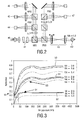
- Fig.2 shows a schematic diagram of elements in a head for near field optical recording.
- the schematic diagram provides an example of a near-field optical player setup used for readout experiments.
- NA 1.9.
- Fig.PBS Polarizing beam-splitter
- NBS Non-polarizing beam-splitter
- ⁇ /2 half-wave plate.
- a split detector 45 is positioned to generate a push-pull tracking error signal.
- a CCD camera 46 is included to observe the irradiance pattern at the exit pupil.
- a half-wave plate ⁇ /2 is used to control the amount of light that the PBS splits and directs towards the RF detector and the push pull detector, respectively.
- the second branch on the right side of the Fig. is used to generate the error signal for air gap control.
- the SIL lens 43 needs to be positioned within the evanescent decay distance from the disk. In our set-up the SIL to disk distance is typically 25 nm.
- a suitable error signal is required.
- a linear signal that is suitable as a gap error signal (GES) can be obtained from the reflected light with a polarization state perpendicular to that of the main beam that is focused on the disk.
- GES gap error signal
- Fig.3 shows calculated reflection curves of the gap error signal.
- the Fig. is based on simulated GES curves on Si disc with no grooves, and indicates reflection against air gap size.
- a first curve 50 shows the total reflection
- a second curve 51 shows reflection for the parallel polarization
- a third curve shows reflection for the perpendicular polarization as a function of the air gap width, each curve showing the result for three NA values.
- the second curve 51 may be used as HF signal 53 for data read-out.
- the amount of the perpendicular polarization state of light reflected at the bottom of the SIL is applied as a gap error signal 54 (GES) to control the air gap.
- GES gap error signal
- the gap error signal is available only in a GES linear range 55 within a near field regime of approximately 50nm.
- the optical head approaches the near-field regime from its initial far-field position through an open-loop operation, and then the air gap servo system is switched into a closed-operation as smooth as possible to avoid any collision of the optical head with the disc.
- Fig.4 shows a prior art approach method by ramp voltage.
- a ramp voltage 56 was applied to a biaxial actuator that positions the lens.
- the left graph shows an applied nonnalized control current versus time, and the right graph shows a normalized position 57 and velocity 58 during approaching from a far-field range 72 to a near-field rage 71. This leads to a constant approaching velocity at the switching instant when air gap servo system starts its closed-loop operation.
- Fig.5 shows a pull-in response of the prior art.
- Curve 61 shows the gap reference values for the air gap
- curve 60 shows the response of gap error signal GES.
- the gap reference for the gap servo loop is not set to its final target value (Ref2), but it is gradually lowered to its final value over a fixed time interval from t1 to t2, which is referred to as 'settling time' 64, while overshoot 63 occurs at t1.
- the air gap servo system can start its closed-loop operation without colliding of the optical head with the disc.
- there exists a design trade-off between the settling time and the overshoot which can limit the overall pull-in performance.
- Fig.6 shows an air gap servo system having mode-switch control.
- the figure presents a schematic diagram of a proposed air-gap servo system, including a digital controller 65 and an actuator 67.
- the controller 65 corresponds to the pull-in controller 32 in Fig.1 , which may includes a hand-over unit 34 corresponding to hand-over controller 69.
- a closed loop operation is performed by air gap controller 70.
- the air gap servo system can be referred to as mode-switching control because the three different control structures are, depending upon the operating condition, switched from one to another during the whole servo action by a state machine 66.
- an approach control 68 is to move the optical head from its initial far-field position into the near-field regime where the linear GES is detected; the hand-over control 69 is to achieve a smooth and fast transient response during the switching from the open-loop approach control into the final closed-loop air gap regulating control; and finally the air-gap control 70 is to maintain the air-gap around a fixed target air gap.
- the pull-in procedure is defined as the combination of the approach control and the hand-over control.
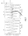
- Fig.7 shows an approach method according to the invention.
- the left graph shows an applied increasing periodical signal 73 as normalized current versus time
- the right graph shows a normalized position 74 and velocity 75 during approaching from a far-field range 72 to a near-field range 71.
- This leads to a sequence of approach instants such as first approach instant 77 where the near-field region is just entered for the first time, and a periodic approaching velocity 75 having about zero speed at the approach instants.
- the velocity is substantially zero at said first approach instant 77 as indicated by arrow 76, at which switching the air gap servo system to the closed-loop operation may be performed.
- the air gap servo system when the optical head moves into a near field position and the gap error signal is available, the air gap servo system is switched into the closed-loop control operation via a hand-over control.
- the gap reference for the gap servo loop is not set to its final target value Ref2, but is generated by a reference generator to provide a smooth trajectory from an initial reference Ref1 to the final target air gap distance Ref2.
- Fig.8 shows a reference generator.
- the actual gap reference y d is smoothly lowered from the starting value Ref1 towards its final target value Ref2.
- the new setpoint value Ref2 is input to a control loop containing a gain unit 81, and a second gain unit 82 coupled to a sum unit for generating an acceleration output a d , which is coupled to a first integrator 83 to generate a velocity output v d , which is coupled to a second integrator 84 to generate a position output y d .
- the first and second integrator are set by starting values v d (0) and y d (0) respectively.
- Fig.9 shows reference trajectories.
- a first curve 91 shows the reference position y d
- a second curve 92 shows the reference velocity v d
- a third curve shows a reference acceleration a d .
- the target distance is smoothly transferred from a first value Ref1 to a second, usually final value Ref2.
- the settling time 94 and the overshoot of the gap reference is determined by the gains of the reference generator.
- the reference generator provides the velocity and the acceleration reference trajectories, v d and a d respectively, for a tracking controller in a hand-over controller.
- Fig.10 shows a diagram of a hand-over controller based on two degree-of-freedom control.
- a controller unit 101 generates a control signal u c to the actuator 67 based on the gap error signal GES in a closed loop mode.
- Gain units indicating various tracking gains for the closed loop mode are configured as usual in a servo controller based on proportional and differential control.
- the tracking control unit is provided with the values y d , v d , and a d as generated by the reference generator to additionally provide the position, velocity and acceleration values in the tracking controller.
- the way of controlling is called a two degree-of-freedom (2-DOF) control because, in this case, the gains of the reference generator determines the settling time of the gap reference whereas the gains of the tracking controller determines the overshoot, or the transient behavior, at the switching instant from the open-loop into the closed-loop operation. Therefore, the two design criteria, the settling time and the overshoot, can be designed independently of each other.
- Fig.11 shows simulated pull-in responses for various reference trajectories with different settling times.
- a left graph shows a reference 111 and response 112 for a settling time of20msec, the mid graph a response 114 for 1Omsec and the right graph a response 115 for 5msec. It can be observed that the overshoot 113 is substantially equal while the settling time is different. Further details of the 2-DOF technique can, for example, be found in G. Franklin, J. Powell, and A. Emami-Naeini, Feedback Control of Dynamic Systems, 4th Ed. Prentice-Hall, 2002 .
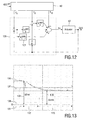
- Fig.12 shows a schematic diagram of the final air-gap control.
- a controller of the PID type (proportional, integrating and differentiating nature) is switched into operation when the GES is close to the target gap value (Ref2).
- Basically it is a standard PID controller, but it can also be any other control method to regulate the air gap around the target gap.
- the integrator 121 has been added with respect to Fig. 10 .
- Fig.13 shows the measurement result of the transient responses from the proposed pull-in procedure.
- a first curve 136 represent the gap error signal GES
- a second curve 137 represents the reference
- a third curve 138 is mode, e.g. the output of the state-machine, which determines the mode of the controller depending on the operating condition.
- a first mode 131 is the approach mode
- a second mode is the hand-over mode 132
- the final state is the closed loop air gap control 133.
- the optical head can successfully settle down to the target gap 135 of 3 3nm from its initial far-field position, via a first reference 134 at 50 nm, without colliding with the disc.
- the effect of the new pull-in method in the air gap servo is that the amplitude-increasing sinusoidal signal has been applied to the actuator when the optical head approaches the near-field regime from its far-field regime. This results in a zero velocity when the air-gap servo system starts its closed-loop operation. As a result, the overshoot at the switching instant can be greatly reduced with a relatively low sampling frequency.
- Fig. 14 shows a measurement of transient responses in closed-loop operation of the servo.
- the gap error signal 140 is shown when the target air gap distance is set at a first setpoint 141 at value 33 nm, and subsequently at a second setpoint 142 at value 24nm.
- the figure shows that, once the air gap servo is in lock, or in the closed-loop operation, then changing its gap to a different value can be done without any overshoot at all. This suggests a sort of two-step pull-in procedure to increase a safety margin against the head collision with the disc.
- the air gap is lowered via such a series of set points. Namely, the first target gap (33nm in Fig.
- the multi step lowering of the gap distance is performed in the closed loop mode, i.e. while the scanning system is already in lock and operational for reading or writing data. This is different from the hand-over mode, wherein the first reference is at the verge of the near-field region, e.g. just where the GES signal becomes available, and the second reference is the working near-field distance.
- the key to the sinusoidal excitation for the approach control is to generate an increasing periodical signal. This may be achieved by modulating an increasing signal, which for example is a ramp signal, with a sinusoidal signal.
- the purpose of the periodical element is to guarantee that the optical head velocity is zero or very small when the head reaches the near-field regime.
- Fig. 15 shows various embodiments of an increasing periodical excitation signal.
- Fig.15A shows a slightly increasing amplitude periodical signal superposed on a ramp.
- Fig 15B shows a strongly increasing amplitude sinusoidal signal superposed on a ramp.
- Fig.15C shows a low-pass filtered staircase signal is applied to the actuator.
- the left graph shows a normalized control current
- the right graph shows the normalized position (upper curve) and velocity (lower curve), the velocity being substantially zero at the approach instants where the lens is near to the surface.
- the frequency of the excitation input signal should be chosen well below the resonance frequency of the underlying actuator to avoid the undesirable resonant oscillation during the approach control.
- the increment of the actuator position between each of the approach instants which is for instance denoted by ⁇ y in Fig.15A , should be smaller than the GES linear range.
- the invention has been mainly explained by embodiments of the air gap servo applied to the specific near field optical recording system as described in doc[1] and doc[2], the invention is also suitable for other record carrier and head systems that need a small air gap between any lens and record carrier surface, such as rectangular optical cards, magneto-optical discs or any other type of information storage system, or a near-field scanning microscope system.
- the words " near-field optical recording" include any such system.
Landscapes
- Physics & Mathematics (AREA)
- Optics & Photonics (AREA)
- Optical Recording Or Reproduction (AREA)
- Optical Head (AREA)
- Moving Of The Head For Recording And Reproducing By Optical Means (AREA)
Claims (9)
- Dispositif pour l'enregistrement en champ proche, d'informations représentées par des marques dans une piste sur un support d'enregistrement (11),
le dispositif comprenant- une tête (22) comprenant une lentille qui doit être positionnée par un actionneur de lentille à une distance de champ proche d'une surface du support d'enregistrement pour générer un spot de balayage sur la piste, et- un contrôleur de hauteur de survol (65) pour commander une hauteur de survol entre la lentille et la surface, lequel contrôleur de hauteur de survol présente un mode d'approche pour amener la lentille d'une distance lointaine à la distance de champ proche,caractérisé en ce que le contrôleur de hauteur de survol est agencé- pour fournir un signal d'excitation périodique croissant à l'actionneur de lentille afin de générer une séquence de périodes dans laquelle la lentille est entraînée de manière à s'approcher de la surface, la lentille, aux instants d'approche dans les périodes, ayant une vitesse pratiquement nulle dans une direction perpendiculaire à la surface, et la séquence de périodes amenant la lentille de plus en plus près de la surface, et- pour commuter sur un mode en boucle fermée lorsque la lentille se trouve dans les limites de la distance de champ proche (55) à un des instants d'approche. - Dispositif suivant la revendication 1, dans lequel le signal d'excitation périodique croissant comprend un signal sinusoïdal.
- Dispositif suivant la revendication 1 ou 2, dans lequel le signal d'excitation périodique croissant comprend un signal périodique d'amplitude croissante.
- Dispositif suivant la revendication 1 ou 2, dans lequel le signal d'excitation périodique croissant comprend une composante de rampe.
- Dispositif suivant la revendication 1, dans lequel le signal d'excitation périodique croissant comprend une composante en escalier filtrée passe-bas.
- Dispositif suivant la revendication 1, dans lequel le contrôleur de hauteur de survol (65) comprend un générateur de référence (80) pour, dans un mode de transfert, fournir une distance de champ proche de référence passant d'une première distance de champ proche cible à une seconde distance de champ proche cible, inférieure, par le biais d'une fonction de transfert.
- Dispositif suivant la revendication 6, dans lequel le générateur de référence est destiné à fournir des valeurs de référence à une unité de contrôleur (101, 120) sur la base d'une technique de commande à deux degrés de liberté dans ledit mode de transfert.
- Procédé d'accrochage pour amener une lentille d'une distance lointaine à une distance de champ proche d'une surface d'un support d'enregistrement (11) en vue d'un enregistrement optique en champ proche, les informations étant représentées par des marques dans une piste sur le support d'enregistrement destinées à être balayées au moyen d'une tête (22) comprenant la lentille,
caractérisé en ce que le procédé comprend- la fourniture d'une excitation périodique croissante à un actionneur de lentille pour générer une séquence de périodes au cours de laquelle la lentille est entraînée pour s'approcher de la surface, la lentille, aux instants d'approche dans les périodes, ayant une vitesse sensiblement nulle dans une direction perpendiculaire à la surface, et la séquence de périodes amenant la lentille de plus en plus près de la surface,- la détection du moment où la lentille se trouve dans les limites de la distance de champ proche à l'un des instants d'approche, et ensuite- la commutation d'un système d'asservissement de hauteur de survol vers un mode en boucle fermée. - Procédé suivant la revendication 8, dans lequel l'excitation périodique croissante comprend un signal sinusoïdal d'amplitude croissante.
Priority Applications (1)
| Application Number | Priority Date | Filing Date | Title |
|---|---|---|---|
| EP05718639A EP1741097B1 (fr) | 2004-04-16 | 2005-04-06 | Servocommande d'ecartement pour enregistrement optique a champ proche |
Applications Claiming Priority (4)
| Application Number | Priority Date | Filing Date | Title |
|---|---|---|---|
| EP04101585 | 2004-04-16 | ||
| EP04104091 | 2004-08-26 | ||
| EP05718639A EP1741097B1 (fr) | 2004-04-16 | 2005-04-06 | Servocommande d'ecartement pour enregistrement optique a champ proche |
| PCT/IB2005/051121 WO2005101391A1 (fr) | 2004-04-16 | 2005-04-06 | Servocommande d'ecartement pour enregistrement optique a champ proche |
Publications (2)
| Publication Number | Publication Date |
|---|---|
| EP1741097A1 EP1741097A1 (fr) | 2007-01-10 |
| EP1741097B1 true EP1741097B1 (fr) | 2008-05-21 |
Family
ID=34963007
Family Applications (1)
| Application Number | Title | Priority Date | Filing Date |
|---|---|---|---|
| EP05718639A Expired - Lifetime EP1741097B1 (fr) | 2004-04-16 | 2005-04-06 | Servocommande d'ecartement pour enregistrement optique a champ proche |
Country Status (8)
| Country | Link |
|---|---|
| US (1) | US20080267036A1 (fr) |
| EP (1) | EP1741097B1 (fr) |
| JP (1) | JP2007533061A (fr) |
| KR (1) | KR20070012671A (fr) |
| AT (1) | ATE396478T1 (fr) |
| DE (1) | DE602005007007D1 (fr) |
| TW (1) | TW200539161A (fr) |
| WO (1) | WO2005101391A1 (fr) |
Families Citing this family (8)
| Publication number | Priority date | Publication date | Assignee | Title |
|---|---|---|---|---|
| WO2007066258A2 (fr) * | 2005-12-06 | 2007-06-14 | Koninklijke Philips Electronics N.V. | Asservissement de hauteur de survol pour enregistrement optique |
| KR20090005620A (ko) * | 2007-07-09 | 2009-01-14 | 삼성전자주식회사 | 근접장 광 디스크 장치 및 포커스 풀인 방법 |
| KR20090024967A (ko) * | 2007-09-05 | 2009-03-10 | 삼성전자주식회사 | 광 디스크 장치 및 그 구동방법 |
| KR101346772B1 (ko) | 2007-09-05 | 2013-12-31 | 연세대학교 산학협력단 | 광 디스크 장치 및 그 구동방법 |
| JP2009158007A (ja) * | 2007-12-26 | 2009-07-16 | Sony Corp | 光学ピックアップ装置、光記録再生装置及びギャップ制御方法 |
| KR100958588B1 (ko) * | 2008-05-22 | 2010-05-18 | 삼성전자주식회사 | 근접장 광디스크 구동기에서 갭 풀인 방법 및 그와 같은기능을 갖는 광디스크 구동 장치 |
| JP2010135029A (ja) * | 2008-12-05 | 2010-06-17 | Sony Corp | 光ディスク装置及び光ディスク駆動制御方法 |
| CN113296422A (zh) * | 2021-04-25 | 2021-08-24 | 上海航天控制技术研究所 | 一种运载火箭半实物仿真试验伺服系统动态特性测试方法 |
Family Cites Families (6)
| Publication number | Priority date | Publication date | Assignee | Title |
|---|---|---|---|---|
| GB9001954D0 (en) * | 1990-01-29 | 1990-03-28 | Smiths Industries Plc | Radar apparatus |
| US5456341A (en) * | 1993-04-23 | 1995-10-10 | Moog Inc. | Method and apparatus for actively adjusting and controlling a resonant mass-spring system |
| US5696647A (en) * | 1994-03-28 | 1997-12-09 | Seagate Technology, Inc. | Method for carrying out seeks in a hard disc drive to limit the generation of acoustic noise including using a slew rate limit |
| JP3833448B2 (ja) * | 2000-07-05 | 2006-10-11 | 株式会社リコー | 光ピックアップ方法および装置および光情報処理装置 |
| US7106683B2 (en) * | 2001-08-31 | 2006-09-12 | Sony Corporation | Optical pickup device and recording/reproducing device |
| JP4228666B2 (ja) * | 2002-11-25 | 2009-02-25 | ソニー株式会社 | 光学ピックアップ装置、記録再生装置及びギャップ検出方法 |
-
2005
- 2005-04-06 EP EP05718639A patent/EP1741097B1/fr not_active Expired - Lifetime
- 2005-04-06 DE DE602005007007T patent/DE602005007007D1/de not_active Expired - Fee Related
- 2005-04-06 US US10/599,862 patent/US20080267036A1/en not_active Abandoned
- 2005-04-06 WO PCT/IB2005/051121 patent/WO2005101391A1/fr not_active Ceased
- 2005-04-06 AT AT05718639T patent/ATE396478T1/de not_active IP Right Cessation
- 2005-04-06 KR KR1020067021267A patent/KR20070012671A/ko not_active Withdrawn
- 2005-04-06 JP JP2007507885A patent/JP2007533061A/ja not_active Withdrawn
- 2005-04-13 TW TW094111677A patent/TW200539161A/zh unknown
Also Published As
| Publication number | Publication date |
|---|---|
| ATE396478T1 (de) | 2008-06-15 |
| EP1741097A1 (fr) | 2007-01-10 |
| TW200539161A (en) | 2005-12-01 |
| DE602005007007D1 (de) | 2008-07-03 |
| US20080267036A1 (en) | 2008-10-30 |
| KR20070012671A (ko) | 2007-01-26 |
| WO2005101391A1 (fr) | 2005-10-27 |
| JP2007533061A (ja) | 2007-11-15 |
Similar Documents
| Publication | Publication Date | Title |
|---|---|---|
| US20080037390A1 (en) | Read/write position controller for optical pickup | |
| EP1741097B1 (fr) | Servocommande d'ecartement pour enregistrement optique a champ proche | |
| EP2290648B1 (fr) | Lentille d'objectif et capture optique comprenant la lentille d'objectif | |
| JP4139994B2 (ja) | 信号記録装置、信号再生装置、及び方法 | |
| JPH01220129A (ja) | 焦点捕捉装置及び方法 | |
| JPH01223640A (ja) | 光学的記録再生装置 | |
| EP1961003B1 (fr) | Asservissement de hauteur de survol pour enregistrement optique | |
| CN100454411C (zh) | 用于光记录的气隙伺服系统 | |
| US4989194A (en) | Optical information processing method of driving auto-focusing and/or auto-tracking means in accordance with a stored servo signal when irradiation of a record medium with light beam is stopped, and apparatus therefor | |
| JPH0765382A (ja) | 光ディスク制御装置 | |
| JPH0510277Y2 (fr) | ||
| KR101346772B1 (ko) | 광 디스크 장치 및 그 구동방법 | |
| JP2609721B2 (ja) | 光学式記録情報読取装置 | |
| JP2008310921A (ja) | 光情報記録再生装置 | |
| JPH0444327B2 (fr) | ||
| KR100628184B1 (ko) | 광 기록재생기의 액츄에이터 제어 장치 | |
| JPH0682468B2 (ja) | 光学的情報記録再生装置 | |
| JPS63140427A (ja) | 高密度記録媒体デイスクトラツク位置制御装置 | |
| JPH08255365A (ja) | 光ディスク装置 | |
| JPH0775076B2 (ja) | フオ−カスサ−ボ引込装置 | |
| JPH0441417B2 (fr) | ||
| JPH069085B2 (ja) | 光学的情報記録再生装置 | |
| JP2001118257A (ja) | 光学的情報記録再生装置 | |
| JPH11161981A (ja) | 光ディスク記録再生装置及び方法並びに光ディスク装置のトラッキングサーボ駆動装置及び方法 | |
| JPH04324124A (ja) | 光ディスクドライブ装置のトラッキング制御装置 |
Legal Events
| Date | Code | Title | Description |
|---|---|---|---|
| PUAI | Public reference made under article 153(3) epc to a published international application that has entered the european phase |
Free format text: ORIGINAL CODE: 0009012 |
|
| 17P | Request for examination filed |
Effective date: 20061116 |
|
| AK | Designated contracting states |
Kind code of ref document: A1 Designated state(s): AT BE BG CH CY CZ DE DK EE ES FI FR GB GR HU IE IS IT LI LT LU MC NL PL PT RO SE SI SK TR |
|
| 17Q | First examination report despatched |
Effective date: 20070509 |
|
| DAX | Request for extension of the european patent (deleted) | ||
| GRAP | Despatch of communication of intention to grant a patent |
Free format text: ORIGINAL CODE: EPIDOSNIGR1 |
|
| GRAS | Grant fee paid |
Free format text: ORIGINAL CODE: EPIDOSNIGR3 |
|
| GRAA | (expected) grant |
Free format text: ORIGINAL CODE: 0009210 |
|
| AK | Designated contracting states |
Kind code of ref document: B1 Designated state(s): AT BE BG CH CY CZ DE DK EE ES FI FR GB GR HU IE IS IT LI LT LU MC NL PL PT RO SE SI SK TR |
|
| REG | Reference to a national code |
Ref country code: GB Ref legal event code: FG4D |
|
| REG | Reference to a national code |
Ref country code: CH Ref legal event code: EP |
|
| REF | Corresponds to: |
Ref document number: 602005007007 Country of ref document: DE Date of ref document: 20080703 Kind code of ref document: P |
|
| REG | Reference to a national code |
Ref country code: IE Ref legal event code: FG4D |
|
| PG25 | Lapsed in a contracting state [announced via postgrant information from national office to epo] |
Ref country code: SI Free format text: LAPSE BECAUSE OF FAILURE TO SUBMIT A TRANSLATION OF THE DESCRIPTION OR TO PAY THE FEE WITHIN THE PRESCRIBED TIME-LIMIT Effective date: 20080521 |
|
| PG25 | Lapsed in a contracting state [announced via postgrant information from national office to epo] |
Ref country code: FI Free format text: LAPSE BECAUSE OF FAILURE TO SUBMIT A TRANSLATION OF THE DESCRIPTION OR TO PAY THE FEE WITHIN THE PRESCRIBED TIME-LIMIT Effective date: 20080521 Ref country code: ES Free format text: LAPSE BECAUSE OF FAILURE TO SUBMIT A TRANSLATION OF THE DESCRIPTION OR TO PAY THE FEE WITHIN THE PRESCRIBED TIME-LIMIT Effective date: 20080901 |
|
| NLV1 | Nl: lapsed or annulled due to failure to fulfill the requirements of art. 29p and 29m of the patents act | ||
| PG25 | Lapsed in a contracting state [announced via postgrant information from national office to epo] |
Ref country code: PL Free format text: LAPSE BECAUSE OF FAILURE TO SUBMIT A TRANSLATION OF THE DESCRIPTION OR TO PAY THE FEE WITHIN THE PRESCRIBED TIME-LIMIT Effective date: 20080521 Ref country code: AT Free format text: LAPSE BECAUSE OF FAILURE TO SUBMIT A TRANSLATION OF THE DESCRIPTION OR TO PAY THE FEE WITHIN THE PRESCRIBED TIME-LIMIT Effective date: 20080521 Ref country code: NL Free format text: LAPSE BECAUSE OF FAILURE TO SUBMIT A TRANSLATION OF THE DESCRIPTION OR TO PAY THE FEE WITHIN THE PRESCRIBED TIME-LIMIT Effective date: 20080521 |
|
| PG25 | Lapsed in a contracting state [announced via postgrant information from national office to epo] |
Ref country code: IS Free format text: LAPSE BECAUSE OF FAILURE TO SUBMIT A TRANSLATION OF THE DESCRIPTION OR TO PAY THE FEE WITHIN THE PRESCRIBED TIME-LIMIT Effective date: 20080921 |
|
| PG25 | Lapsed in a contracting state [announced via postgrant information from national office to epo] |
Ref country code: SE Free format text: LAPSE BECAUSE OF FAILURE TO SUBMIT A TRANSLATION OF THE DESCRIPTION OR TO PAY THE FEE WITHIN THE PRESCRIBED TIME-LIMIT Effective date: 20080821 Ref country code: CZ Free format text: LAPSE BECAUSE OF FAILURE TO SUBMIT A TRANSLATION OF THE DESCRIPTION OR TO PAY THE FEE WITHIN THE PRESCRIBED TIME-LIMIT Effective date: 20080521 Ref country code: DK Free format text: LAPSE BECAUSE OF FAILURE TO SUBMIT A TRANSLATION OF THE DESCRIPTION OR TO PAY THE FEE WITHIN THE PRESCRIBED TIME-LIMIT Effective date: 20080521 Ref country code: LT Free format text: LAPSE BECAUSE OF FAILURE TO SUBMIT A TRANSLATION OF THE DESCRIPTION OR TO PAY THE FEE WITHIN THE PRESCRIBED TIME-LIMIT Effective date: 20080521 |
|
| PG25 | Lapsed in a contracting state [announced via postgrant information from national office to epo] |
Ref country code: BE Free format text: LAPSE BECAUSE OF FAILURE TO SUBMIT A TRANSLATION OF THE DESCRIPTION OR TO PAY THE FEE WITHIN THE PRESCRIBED TIME-LIMIT Effective date: 20080521 Ref country code: PT Free format text: LAPSE BECAUSE OF FAILURE TO SUBMIT A TRANSLATION OF THE DESCRIPTION OR TO PAY THE FEE WITHIN THE PRESCRIBED TIME-LIMIT Effective date: 20081021 Ref country code: RO Free format text: LAPSE BECAUSE OF FAILURE TO SUBMIT A TRANSLATION OF THE DESCRIPTION OR TO PAY THE FEE WITHIN THE PRESCRIBED TIME-LIMIT Effective date: 20080521 Ref country code: SK Free format text: LAPSE BECAUSE OF FAILURE TO SUBMIT A TRANSLATION OF THE DESCRIPTION OR TO PAY THE FEE WITHIN THE PRESCRIBED TIME-LIMIT Effective date: 20080521 |
|
| PLBE | No opposition filed within time limit |
Free format text: ORIGINAL CODE: 0009261 |
|
| STAA | Information on the status of an ep patent application or granted ep patent |
Free format text: STATUS: NO OPPOSITION FILED WITHIN TIME LIMIT |
|
| 26N | No opposition filed |
Effective date: 20090224 |
|
| PG25 | Lapsed in a contracting state [announced via postgrant information from national office to epo] |
Ref country code: BG Free format text: LAPSE BECAUSE OF FAILURE TO SUBMIT A TRANSLATION OF THE DESCRIPTION OR TO PAY THE FEE WITHIN THE PRESCRIBED TIME-LIMIT Effective date: 20080821 Ref country code: EE Free format text: LAPSE BECAUSE OF FAILURE TO SUBMIT A TRANSLATION OF THE DESCRIPTION OR TO PAY THE FEE WITHIN THE PRESCRIBED TIME-LIMIT Effective date: 20080521 |
|
| PG25 | Lapsed in a contracting state [announced via postgrant information from national office to epo] |
Ref country code: IT Free format text: LAPSE BECAUSE OF FAILURE TO SUBMIT A TRANSLATION OF THE DESCRIPTION OR TO PAY THE FEE WITHIN THE PRESCRIBED TIME-LIMIT Effective date: 20080521 |
|
| PGFP | Annual fee paid to national office [announced via postgrant information from national office to epo] |
Ref country code: FR Payment date: 20090429 Year of fee payment: 5 |
|
| PGFP | Annual fee paid to national office [announced via postgrant information from national office to epo] |
Ref country code: DE Payment date: 20090623 Year of fee payment: 5 Ref country code: GB Payment date: 20090430 Year of fee payment: 5 |
|
| REG | Reference to a national code |
Ref country code: CH Ref legal event code: PL |
|
| PG25 | Lapsed in a contracting state [announced via postgrant information from national office to epo] |
Ref country code: LI Free format text: LAPSE BECAUSE OF NON-PAYMENT OF DUE FEES Effective date: 20090430 Ref country code: CH Free format text: LAPSE BECAUSE OF NON-PAYMENT OF DUE FEES Effective date: 20090430 |
|
| PG25 | Lapsed in a contracting state [announced via postgrant information from national office to epo] |
Ref country code: IE Free format text: LAPSE BECAUSE OF NON-PAYMENT OF DUE FEES Effective date: 20090406 Ref country code: MC Free format text: LAPSE BECAUSE OF NON-PAYMENT OF DUE FEES Effective date: 20090430 |
|
| PG25 | Lapsed in a contracting state [announced via postgrant information from national office to epo] |
Ref country code: GR Free format text: LAPSE BECAUSE OF FAILURE TO SUBMIT A TRANSLATION OF THE DESCRIPTION OR TO PAY THE FEE WITHIN THE PRESCRIBED TIME-LIMIT Effective date: 20080822 |
|
| GBPC | Gb: european patent ceased through non-payment of renewal fee |
Effective date: 20100406 |
|
| REG | Reference to a national code |
Ref country code: FR Ref legal event code: ST Effective date: 20101230 |
|
| PG25 | Lapsed in a contracting state [announced via postgrant information from national office to epo] |
Ref country code: DE Free format text: LAPSE BECAUSE OF NON-PAYMENT OF DUE FEES Effective date: 20101103 |
|
| PG25 | Lapsed in a contracting state [announced via postgrant information from national office to epo] |
Ref country code: GB Free format text: LAPSE BECAUSE OF NON-PAYMENT OF DUE FEES Effective date: 20100406 |
|
| PG25 | Lapsed in a contracting state [announced via postgrant information from national office to epo] |
Ref country code: LU Free format text: LAPSE BECAUSE OF NON-PAYMENT OF DUE FEES Effective date: 20090406 |
|
| PG25 | Lapsed in a contracting state [announced via postgrant information from national office to epo] |
Ref country code: HU Free format text: LAPSE BECAUSE OF FAILURE TO SUBMIT A TRANSLATION OF THE DESCRIPTION OR TO PAY THE FEE WITHIN THE PRESCRIBED TIME-LIMIT Effective date: 20081122 |
|
| PG25 | Lapsed in a contracting state [announced via postgrant information from national office to epo] |
Ref country code: TR Free format text: LAPSE BECAUSE OF FAILURE TO SUBMIT A TRANSLATION OF THE DESCRIPTION OR TO PAY THE FEE WITHIN THE PRESCRIBED TIME-LIMIT Effective date: 20080521 |
|
| PG25 | Lapsed in a contracting state [announced via postgrant information from national office to epo] |
Ref country code: CY Free format text: LAPSE BECAUSE OF FAILURE TO SUBMIT A TRANSLATION OF THE DESCRIPTION OR TO PAY THE FEE WITHIN THE PRESCRIBED TIME-LIMIT Effective date: 20080521 |
|
| PG25 | Lapsed in a contracting state [announced via postgrant information from national office to epo] |
Ref country code: FR Free format text: LAPSE BECAUSE OF NON-PAYMENT OF DUE FEES Effective date: 20100430 |