EP1741970A1 - Sprühgerät für Schmierstoffe oder dgl. Fluid - Google Patents
Sprühgerät für Schmierstoffe oder dgl. Fluid Download PDFInfo
- Publication number
- EP1741970A1 EP1741970A1 EP06005935A EP06005935A EP1741970A1 EP 1741970 A1 EP1741970 A1 EP 1741970A1 EP 06005935 A EP06005935 A EP 06005935A EP 06005935 A EP06005935 A EP 06005935A EP 1741970 A1 EP1741970 A1 EP 1741970A1
- Authority
- EP
- European Patent Office
- Prior art keywords
- lubricant
- pressure
- valve
- pressure accumulator
- pump
- Prior art date
- Legal status (The legal status is an assumption and is not a legal conclusion. Google has not performed a legal analysis and makes no representation as to the accuracy of the status listed.)
- Granted
Links
- 239000000314 lubricant Substances 0.000 title claims abstract description 52
- 239000012530 fluid Substances 0.000 title claims abstract description 7
- 238000005507 spraying Methods 0.000 title claims abstract description 5
- 239000007921 spray Substances 0.000 claims abstract description 15
- 239000004568 cement Substances 0.000 claims description 2
- 239000003921 oil Substances 0.000 claims description 2
- 238000009423 ventilation Methods 0.000 claims description 2
- 238000005273 aeration Methods 0.000 description 2
- 208000002173 dizziness Diseases 0.000 description 1
- 230000007613 environmental effect Effects 0.000 description 1
- 238000010438 heat treatment Methods 0.000 description 1
- 238000003898 horticulture Methods 0.000 description 1
- 238000005461 lubrication Methods 0.000 description 1
- 238000012423 maintenance Methods 0.000 description 1
- 238000000034 method Methods 0.000 description 1
- 230000003287 optical effect Effects 0.000 description 1
- 230000001960 triggered effect Effects 0.000 description 1
Images

Classifications
-
- F—MECHANICAL ENGINEERING; LIGHTING; HEATING; WEAPONS; BLASTING
- F16—ENGINEERING ELEMENTS AND UNITS; GENERAL MEASURES FOR PRODUCING AND MAINTAINING EFFECTIVE FUNCTIONING OF MACHINES OR INSTALLATIONS; THERMAL INSULATION IN GENERAL
- F16N—LUBRICATING
- F16N7/00—Arrangements for supplying oil or unspecified lubricant from a stationary reservoir or the equivalent in or on the machine or member to be lubricated
- F16N7/38—Arrangements for supplying oil or unspecified lubricant from a stationary reservoir or the equivalent in or on the machine or member to be lubricated with a separate pump; Central lubrication systems
Definitions
- the invention relates to a device for spraying narrow spaces, z.
- a device for spraying narrow spaces, z As of inner races of races with loose ring attachment to rotary kilns, such as cement drums, with lubricants, such as pressure oils, or for similar applications of fluids to be sprayed.
- the raceway innerliner must be lubricated daily with a sprayable lubricant according to the manufacturer. So far, this has been done with great effort and under difficult conditions (temperature) z. B. performed with hand syringes in combination with lances.
- pressure pumps were used, which are normally used in horticulture.
- the disadvantage here is that only low viscosity lubricant can be pumped with such pumps.
- Object of the present invention is to provide a sprayer of the type mentioned, in which these disadvantages are eliminated, which is used under difficult environmental conditions and the lubricant or the like. Sprayed fluid far and accurately. Instead of fluid in general, only lubricant will be discussed below without thereby restricting the scope of protection.
- the device having a hydraulic unit with at least one pressure accumulator for receiving the lubricant under elevated pressure, at least one spray nozzle, a pump for conveying lubricant from a lubricant tank to the at least one pressure accumulator and with at least one lubricant dispensing valve which can be opened by means of an electrical pulse in a connecting line between the at least one pressure accumulator and the at least one spray nozzle.
- Such a device can be used automatically. It is achieved by simple means that spaces can be sprayed almost horizontally and positionally accurate at a distance of up to one meter, the start pulse for the lubricant delivery can be triggered by an electrical sensor.
- a storage charging valve between the pump and the at least one pressure accumulator can ensure that the pressure accumulator is automatically fed, so that it is ensured that the lubricant is always kept at the required operating pressure.
- a throttle check valve which is switched on between the at least one pressure accumulator and the lubricant delivery valve and / or between the accumulator charging valve and the at least one pressure accumulator serves as a factor in the adjustment of the metered quantity. Other factors include the switching time of the lubricant dispensing valve and the selection of the spray nozzle.
- the pressure in the accumulator and / or the pump pressure can / can each with a Greziermesser z.
- At least one pressure accumulator and / or the at least one lubricant dispensing valve may be assigned a pressure relief device. This is z. B. then actuated when an intervention in the system is required.
- the pump is designed as a geared piston pump.
- the at least one pressure accumulator is advantageously a diaphragm accumulator.
- a 2/2-way solenoid valve is proposed.
- either the at least one spray nozzle itself can be exchanged for another or the spray nozzle with exchangeable orifice.
- the pressure relief device may be formed as a ball valve and / or solenoid valve.
- the hydraulic unit preferably be arranged as a complete unit or at least a part thereof on or on the lubricant tank itself.
- An advantageous mode of operation results when the operating pressure of the lubricant to a predetermined value of z. B. about 90 bar and the Accumulator filling pressure to a predetermined value of z. B. is adjustable about 60 bar.
- the pump for Nachellen lubricant is connectable.
- the lubricant tank is equipped, for example, except with a filling and aeration device with a level switch for the lubricant supply.
- the hydraulic unit 10 shown in Fig. 1 is mounted from the provision of the lubricant to the load terminals as a complete unit on the lid of a lubricant tank 20.
- z. B designed as a gear piston pump with a constant flow rate pump 30, which is located below the lubricant tank lid.
- the entire valve control of the hydraulic unit 10 with a pressure accumulator 70 and the pump control is installed on the tank lid.
- the pressure can be adjusted so that the primary pressure is about 90 bar and the storage pressure is 60 bar.
- a filling pressure gauge (manometer) 50 is installed as optical control.
- the pressure accumulator 70 thus ensures constant availability of the lubricant in the operating state.
- a safety valve 80 For the overpressure protection is a safety valve (pressure relief valve) 80. Furthermore, in the connecting line between the pump 30 and pressure accumulator 70, a Speicherachladladentil 40 is provided which ensures the provision of the lubricant in the pressure accumulator 70 below the desired storage pressure. The lubricant is released, for example, by triggering a sensor via a throttle check valve 60 through the lubricant dispensing valves 100.1, 100.2 from the spray nozzles 110.1 and 110.2.
- z. B. designed as a ball valve pressure relief device 90, the system, for. B. when an intervention is required to be depressurized.
- the pump should be restarted approx. 5 minutes before the pause time has elapsed.
- the lubricant tank 20 is conventionally equipped with a filling and aeration device 21 and a level switch 22.
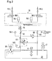
- the hydraulic plan is compared to that of Fig. 1 modified by a partial unit with two the respective spray nozzles 110.1 and 110.2 associated pressure accumulators 70.1 and 70.2 separately is provided by the mounted on the lubricant tank 20 remaining sub-aggregate.
- the accumulators 70.1, 70.2 are not connected as the pressure accumulator 70 of FIG. 1 between throttle check valve 60 and safety valve 80, but downstream of the throttle check valve 60.
- the pressures are monitored by means of pressure gauges 50.1 and 50.2 between pump 30 and store topping valve 40 and between store topping valve 40 and throttle check valve 60.
- the pressure relief device 90 designed as a ball valve is supplemented by a pressure relief device 91 designed as a solenoid valve.
- the operation of the hydraulic unit 10 of FIG. 2 is similar to that of FIG. 1 otherwise.
Landscapes
- Engineering & Computer Science (AREA)
- General Engineering & Computer Science (AREA)
- Mechanical Engineering (AREA)
- Coating Apparatus (AREA)
- Lubricants (AREA)
- Nozzles (AREA)
Abstract
Description
- Die Erfindung bezieht sich auf ein Gerät zum Besprühen von engen Zwischenräumen, z. B. von Innenbahnen von Laufringen mit loser Laufringbefestigung an Drehöfen, wie Zementtrommeln, mit Schmierstoffen, wie Druckölen, oder für vergleichbare Anwendungen von zu versprühenden Fluiden.
- Beispielsweise an Laufringen mit loser Laufringbefestigung muss nach Herstellerangaben die Laufringinnenbahn mit einem sprühbaren Schmiermittel täglich geschmiert werden. Bislang wurde dies mit großem Aufwand und unter schwierigen Bedingungen (Temperatur) z. B. mit Handspritzen in Kombination mit Lanzen durchgeführt. Verwendet wurden in der Regel Druckpumpen, die normalerweise im Gartenbau Anwendung finden. Nachteilig hierbei ist, dass mit solchen Pumpen nur dünnflüssige Schmiermittel verpumpt werden können. Ein noch größerer Nachteil ist jedoch die hohe Unfallgefahr bei dieser manuellen Schmiermethode aufgrund der hohen Temperaturen und aufgrund der Drehbewegung des Ofens, welche Schwindel beim Wartungspersonal verursacht. Weiterhin ist eine Dosierung und punktgenaue Aufbringung des Schmierstoffs mit der Hand nur sehr begrenzt möglich, zumal ein Drehofen im Betrieb und speziell während der Aufheizphase um einige Zentimeter "wandert". Ähnliche Probleme können auch beim Versprühen anderer Fluide bestehen.
- Aufgabe der vorliegenden Erfindung ist es, ein Sprühgerät der eingangs genannten Art vorzuschlagen, bei welchem diese Nachteile beseitigt sind, welches unter schwierigen Umgebungsbedingungen einsetzbar ist sowie den Schmierstoff oder dgl. Fluid weit und zielgenau versprüht. Statt von Fluid allgemein wird im Folgenden nur von Schmierstoff gesprochen, ohne dadurch den Schutzbereich beschränken zu wollen.
- Diese Aufgabe wird erfindungsgemäß bspw. im Wesentlichen dadurch gelöst, dass das Gerät ein Hydraulikaggregat aufweist, mit wenigstens einem Druckspeicher für die Aufnahme des Schmierstoffs unter erhöhtem Druck, wenigstens einer Sprühdüse, einer Pumpe zur Förderung von Schmierstoff von einem Schmierstofftank zu dem wenigstens einen Druckspeicher und mit wenigstens einem mittels elektrischen Impulses öffenbaren Schmierstoffabgabeventil in einer Verbindungsleitung zwischen dem wenigstens einem Druckspeicher und der wenigstens einen Sprühdüse.
- Ein derartiges Gerät ist selbsttätig einsetzbar. Es wird mit einfachen Mitteln erreicht, dass Zwischenräume in einem Abstand von bis zu einem Meter nahezu waagrecht und positionsgenau besprüht werden können, wobei der Startimpuls für die Schmierstoffabgabe über einen elektrischen Sensor ausgelöst werden kann.
- Ein Speichernachladeventil zwischen der Pumpe und dem wenigstens einen Druckspeicher kann dafür sorgen, dass selbsttätig eine Nachspeisung des Druckspeichers erfolgt, so dass für eine ständige Bereithaltung des Schmierstoffes unter dem erforderlichen Betriebsdruck gewährleistet ist.
- Ein zwischen dem wenigstens einen Druckspeicher und dem Schmierstoffabgabeventil und/oder zwischen dem Speichernachladeventil und dem wenigstens einen Druckspeicher eingeschaltetes Drosselrückschlagventil dient als ein Faktor der Einstellung der Dosiermenge. Weitere Faktoren hierfür sind die Schaltzeit des Schmierstoffabgabeventils sowie die Auswahl der Sprühdüse.
- Der Druck in dem Druckspeicher und/oder der Pumpendruck können/kann mit je einem Fülldruckmesser z. B. optisch überwacht werden, während ein dem wenigstens einen Druckspeicher zugeordnetes Sicherheitsventil unzulässige Überdrucke vermeidet.
- Gemäß einem weiteren Erfindungsmerkmal kann dem wenigstens einen Druckspeicher und/oder dem wenigstens einen Schmierstoffabgabeventil eine Druckentlastungseinrichtung zugeordnet sein. Diese wird z. B. dann betätigt, wenn ein Eingriff in die Anlage erforderlich ist.
- Für einen möglichst gleichmäßigen Druck in der Anlage wird gesorgt, wenn die Pumpe als Zahnradkolbenpumpe ausgebildet ist.
- Der wenigstens eine Druckspeicher ist vorteilhafterweise ein Membranspeicher.
- Für das wenigstens eine Schmierstoffabgabeventil wird ein 2/2-Wege-Sitz-Magnetventil vorgeschlagen.
- Zur Anpassung an unterschiedliche Dosiermengen kann entweder die wenigstens eine Sprühdüse selbst gegen eine andere austauschbar oder die Sprühdüse mit austauschbarer Blende ausgestattet sein.
- Die Druckentlastungseinrichtung kann als Kugelhahn und/oder Magnetventil ausgebildet sein.
- Fernerhin wird vorgeschlagen, dass Hydraulikaggregat vorzugsweise als komplette Einheit oder wenigstens ein Teil davon auf bzw. an dem Schmierstofftank selbst anzuordnen.
- Eine vorteilhafte Betriebsweise ergibt sich dann, wenn der Betriebsdruck des Schmierstoffs auf einen vorgegebenen Wert von z. B. etwa 90 bar und der Speicherfülldruck auf einen vorgegebenen Wert von z. B. etwa 60 bar einstellbar ist.
- Ferner ist vorzugsweise vorgesehen, dass bei einem Druckabfall in dem Druckspeicher auf einen Wert unterhalb eines vorgegebenen Wertes von z. B. etwa 85 bar die Pumpe zum Nachfördern von Schmierstoff anschaltbar ist.
- Der Schmierstofftank ist bspw. außer mit einer Einfüll- und Belüftungseinrichtung mit einem Niveauschalter für den Schmierstoffvorrat ausgerüstet.
- Weitere Ziele, Merkmale, Vorteile und Anwendungsmöglichkeiten der Erfindung ergeben sich aus der nachfolgenden Beschreibung von Ausführungsbeispielen anhand der Zeichnung. Dabei bilden alle beschriebenen und/oder bildlich dargestellten Merkmale für sich oder in beliebiger sinnvoller Kombination den Gegenstand der Erfindung, auch unabhängig von deren Zusammenfassung in einzelnen Ansprüchen oder deren Rückbeziehung.
-
- Fig. 1
- einen Hydraulikplan des Hydraulikaggregats bei einem erfindungsgemäßen Sprühgerät für Schmierstoffe gemäß einer Ausführungsart, und
- Fig. 2
- einen Hydraulikplan ähnlich Fig. 1 für eine andere Ausführungsart der Erfindung.
- Das in Fig. 1 dargestellte Hydraulikaggregat 10 ist von der Bereitstellung des Schmierstoffs bis zu den Verbraucheranschlüssen als vollständige Einheit auf dem Deckel eines Schmierstofftanks 20 montiert. Als Energiequelle dient z. B. eine als Zahnradkolbenpumpe mit konstanter Fördermenge ausgebildete Pumpe 30, welche sich unterhalb des Schmierstofftankdeckels befindet. Die gesamte Ventilsteuerung des Hydraulikaggregats 10 mit einem Druckspeicher 70 und der Pumpensteuerung ist auf dem Tankdeckel installiert. Die Druckeinstellung kann so erfolgen, dass der Primärdruck bei etwa 90 bar und der Speicherfülldruck bei 60 bar liegt. Zur Überwachung der eingestellten Pumpenleistung ist als optische Kontrolle ein Fülldruckmesser (Manometer) 50 installiert. Der Druckspeicher 70 sorgt somit für ständige Bereithaltung des Schmierstoffes im Betriebszustand. Zur Überdrucksicherung dient ein Sicherheitsventil (Druckbegrenzungsventil) 80. Ferner ist in der Verbindungsleitung zwischen Pumpe 30 und Druckspeicher 70 ein Speichernachladeventil 40 vorgesehen, welches die Bereitstellung des Schmierstoffes in dem Druckspeicher 70 unter dem gewünschten Speicherfülldruck gewährleistet. Die Schmierstoffabgabe erfolgt z.B. durch Auslösen eines Sensors über ein Drosselrückschlagventil 60 durch die Schmierstoffabgabeventile 100.1, 100.2 aus den Sprühdüsen 110.1 und 110.2.
- Ist bspw. ein Druckabfall auf ca. 85 bar erreicht, so schaltet die Pumpe 30 selbsttätig ein. Mit Hilfe der z. B. als Kugelhahn ausgebildeten Druckentlastungseinrichtung 90 kann das System, z. B. wenn ein Eingriff erforderlich ist, druckentlastet werden.
- Bei längeren Stillstandszeiten ist es empfehlenswert, die Pumpe 30 abzuschalten. Der erneute Pumpenstart sollte ca. 5 Minuten vor Ablauf der Pausenzeit erfolgen.
- Der Schmierstofftank 20 ist in herkömmlicherweise mit einer Einfüll- und Belüftungseinrichtung 21 und einem Niveauschalter 22 ausgerüstet.
- Bei dem Ausführungsbeispiel von Fig. 2 ist der Hydraulikplan gegenüber dem von Fig. 1 abgeändert, indem ein Teilaggregat mit zwei den jeweiligen Sprühdüsen 110.1 und 110.2 zugeordneten Druckspeichern 70.1 und 70.2 gesondert von dem auf dem Schmierstofftank 20 befestigten übrigen Teilaggregat vorgesehen ist.
- Die Druckspeicher 70.1, 70.2 sind dabei nicht wie der Druckspeicher 70 nach Fig. 1 zwischen Drosselrückschlagventil 60 und Sicherheitsventil 80 angeschlossen, sondern dem Drosselrückschlagventil 60 nachgeordnet. Die Drucke werden mittels Manometern 50.1 und 50.2 zwischen Pumpe 30 und Speichernachladeventil 40 sowie zwischen Speichernachladeventil 40 und Drosselrückschlagventil 60 überwacht. Die als Kugelhahn ausgebildete Druckentlastungseinrichtung 90 ist durch eine als Magnetventil ausgebildete Druckentlastungseinrichtung 91 ergänzt. Die Funktionsweise des Hydraulikaggregats 10 nach Fig. 2 ist dem nach Fig. 1 im übrigen ähnlich.
-
- 10
- Hydraulikaggregat
- 20
- Schmierstofftank
- 21
- Einfüll- und Belüftungseinrichtung
- 22
- Niveauschalter
- 30
- Pumpe
- 40
- Speichernachladeventil
- 50; 50.1, 50.2
- Fülldruckmesser (Manometer)
- 60
- Drosselrückschlagventil
- 70; 70.1, 70.2
- Druckspeicher
- 80
- Sicherheitsventil (Druckbegrenzungsventil)
- 90
- Druckentlastungseinrichtung (Kugelhahn)
- 91
- Druckentlastungseinrichtung (Magnetventil)
- 100.1
- Schmierstoffabgabeventil
- 100.2
- Schmierstoffabgabeventil
- 110.1
- Sprühdüse
- 110.2
- Sprühdüse
Claims (15)
- Gerät zum Besprühen z. B. von engen Zwischenräumen, z. B. von Innenbahnen von Laufringen mit loser Laufringbefestigung an Drehöfen, wie Zementtrommeln, mit Schmierstoffen, wie Druckölen, oder für vergleichbare Anwendungen von Fluiden gekennzeichnet durch ein Hydraulikaggregat (10) mit wenigstens einem Druckspeicher (70; 70.1, 70.2) für die Aufnahme des Schmierstoffs unter erhöhtem Druck, wenigstens einer Sprühdüse (110.1, 110.2), einer Pumpe (30) zur Förderung von Schmierstoff von einem Schmierstofftank (20) zu dem wenigstens einen Druckspeicher (70; 70.1, 70.2) und mit wenigstens einem mittels elektrischen Startimpulses öffenbaren Schmierstoffabgabeventil (100.1, 100.2) in einer Verbindungsleitung zwischen dem wenigstens einen Druckspeicher (70; 70.1, 70.2) und der wenigstens einen Sprühdüse (110.1, 110.2).
- Gerät nach Anspruch 1, dadurch gekennzeichnet, dass zwischen der Pumpe (30) und dem wenigstens einen Druckspeicher (70; 70.1, 70.2) ein Speichernachladeventil (40) eingeschaltet ist.
- Gerät nach Anspruch 1 oder 2, dadurch gekennzeichnet, dass zwischen dem wenigstens einen Druckspeicher (70; 70.1, 70.2) und dem Schmierstoffabgabeventil (100.1, 100.2) und/oder zwischen dem Speichernachladeventil (40) und dem wenigstens einen Druckspeicher (70; 70.1, 70.2) ein Drosselrückschlagventil (60) eingeschaltet ist.
- Gerät nach einem der vorhergehenden Ansprüche, dadurch gekennzeichnet, dass zwischen dem wenigstens einen Druckspeicher (70; 70.1, 70.2) und dem Speichernachladeventil (40) und/oder zwischen der Pumpe (30) und dem Speichernachladeventil (40) wenigstens ein Fülldruckmesser (50; 50.1, 50.2) eingeschaltet ist.
- Gerät nach einem der vorhergehenden Ansprüche, dadurch gekennzeichnet, dass dem wenigstens einen Druckspeicher (70: 70.1, 70.2) ein Sicherheitsventil (80) zugeordnet ist.
- Gerät nach einem der vorhergehenden Ansprüche, dadurch gekennzeichnet, dass dem wenigstens einen Druckspeicher (70; 70.1, 70.2) und/oder dem wenigstens einen Schmierstoffabgabeventil (100.1, 100.2) eine Druckentlastungseinrichtung (90, 91) zugeordnet ist.
- Gerät nach einem der vorhergehenden Ansprüche, dadurch gekennzeichnet, dass die Pumpe (20) als Zahnradkolbenpumpe ausgebildet ist.
- Gerät nach einem der vorhergehenden Ansprüche, dadurch gekennzeichnet, dass der wenigstens eine Druckspeicher (70; 70.1, 70.2) als Membranspeicher ausgebildet ist.
- Gerät nach einem der vorhergehenden Ansprüche, dadurch gekennzeichnet, dass das wenigstens eine Schmierstoffabgabeventil (100.1, 100.2) als 2/2-Wegesitz-Magnetventil ausgebildet ist.
- Gerät nach einem der vorhergehenden Ansprüche, dadurch gekennzeichnet, dass die wenigstens eine Sprühdüse (110.1, 110.2) entweder selbst austauschbar oder mit austauschbarer Blende ausgestattet ist.
- Gerät nach einem der vorhergehenden Ansprüche, dadurch gekennzeichnet, dass die Druckentlastungseinrichtung (90, 91) als Kugelhahn, Magnetventil und/oder dgl. ausgebildet ist.
- Gerät nach einem der vorhergehenden Ansprüche, dadurch gekennzeichnet, dass das Hydraulikaggregat (10), vorzugsweise als komplette Einheit, auf bzw. an dem Schmierstofftank (20) angeordnet ist.
- Gerät nach einem der vorhergehenden Ansprüche, dadurch gekennzeichnet, dass der Primärdruck des Schmierstoffs auf einen vorgegebenen Wert von z.B. etwa 90 bar und der Speicherfülldruck auf einen vorgegebenen Wert von z.B. etwa 60 bar einstellbar ist.
- Gerät nach einem der vorhergehenden Ansprüche, dadurch gekennzeichnet, dass bei einem Druckabfall in dem wenigstens einen Druckspeicher (70; 70.1, 70.2) auf einen Wert unterhalb eines vorgegebenen Wertes von z.B. etwa 85 bar die Pumpe (30) zum Nachfördern von Schmierstoff selbsttätig anschaltbar ist.
- Gerät nach einem der vorhergehenden Ansprüche, dadurch gekennzeichnet, dass dem Schmierstofftank (20) eine Einfüll- und Belüftungseinrichtung (21) und/oder ein Niveauschalter (22) zugeordnet sind/ist.
Priority Applications (1)
| Application Number | Priority Date | Filing Date | Title |
|---|---|---|---|
| PL06005935T PL1741970T3 (pl) | 2005-06-30 | 2006-03-23 | Przyrząd rozpylający do środków smarowych lub tp. płynu |
Applications Claiming Priority (1)
| Application Number | Priority Date | Filing Date | Title |
|---|---|---|---|
| DE202005009892U DE202005009892U1 (de) | 2005-06-30 | 2005-06-30 | Sprühgerät für Schmierstoffe o.dgl. Fluid |
Publications (2)
| Publication Number | Publication Date |
|---|---|
| EP1741970A1 true EP1741970A1 (de) | 2007-01-10 |
| EP1741970B1 EP1741970B1 (de) | 2008-03-19 |
Family
ID=34983524
Family Applications (1)
| Application Number | Title | Priority Date | Filing Date |
|---|---|---|---|
| EP06005935A Expired - Lifetime EP1741970B1 (de) | 2005-06-30 | 2006-03-23 | Sprühgerät für Schmierstoffe oder dgl. Fluid |
Country Status (6)
| Country | Link |
|---|---|
| EP (1) | EP1741970B1 (de) |
| AT (1) | ATE389847T1 (de) |
| DE (2) | DE202005009892U1 (de) |
| DK (1) | DK1741970T3 (de) |
| ES (1) | ES2302269T3 (de) |
| PL (1) | PL1741970T3 (de) |
Cited By (1)
| Publication number | Priority date | Publication date | Assignee | Title |
|---|---|---|---|---|
| CN103786066A (zh) * | 2014-01-27 | 2014-05-14 | 沈机集团(香港)有限公司 | 液压站集中润滑系统 |
Citations (9)
| Publication number | Priority date | Publication date | Assignee | Title |
|---|---|---|---|---|
| DE3129048A1 (de) * | 1981-07-23 | 1983-02-10 | De Limon Fluhme GmbH & Co, 4000 Düsseldorf | Zentralschmieranlage |
| FR2613032A2 (fr) * | 1984-03-19 | 1988-09-30 | Craf | Dispositif de graissage centralise |
| DE3718571A1 (de) * | 1987-06-03 | 1988-12-22 | Limon Fluhme & Co De | Vorrichtung zur schmierung von loslagern |
| US4904505A (en) * | 1988-03-18 | 1990-02-27 | Armco Inc. | Lubricant mist coating of metal sheet |
| EP0578405A2 (de) * | 1992-07-07 | 1994-01-12 | Castrol Limited | Schmiervorrichtung für Kraftantrieb mit Zähnrädern grossen Durchmessers |
| DE4406099A1 (de) * | 1994-02-25 | 1995-08-31 | Bielomatik Leuze & Co | Schmiervorrichtung zur Versorgung mobiler Schmierstellen |
| JPH11223298A (ja) * | 1998-02-05 | 1999-08-17 | Nanshin Kiko Kk | タイミング式自動給油装置 |
| WO2001011181A1 (en) * | 1999-08-11 | 2001-02-15 | Vermeer Manufacturing Company | Automated lubricant dispensing system and method for a horizontal directional drilling machine |
| US6405810B1 (en) * | 1999-08-25 | 2002-06-18 | Lincoln Industrial Corporation | Method of lubricating and lubricant spraying apparatus |
-
2005
- 2005-06-30 DE DE202005009892U patent/DE202005009892U1/de not_active Expired - Lifetime
-
2006
- 2006-03-23 EP EP06005935A patent/EP1741970B1/de not_active Expired - Lifetime
- 2006-03-23 ES ES06005935T patent/ES2302269T3/es not_active Expired - Lifetime
- 2006-03-23 PL PL06005935T patent/PL1741970T3/pl unknown
- 2006-03-23 DE DE502006000483T patent/DE502006000483D1/de not_active Expired - Fee Related
- 2006-03-23 AT AT06005935T patent/ATE389847T1/de active
- 2006-03-23 DK DK06005935T patent/DK1741970T3/da active
Patent Citations (9)
| Publication number | Priority date | Publication date | Assignee | Title |
|---|---|---|---|---|
| DE3129048A1 (de) * | 1981-07-23 | 1983-02-10 | De Limon Fluhme GmbH & Co, 4000 Düsseldorf | Zentralschmieranlage |
| FR2613032A2 (fr) * | 1984-03-19 | 1988-09-30 | Craf | Dispositif de graissage centralise |
| DE3718571A1 (de) * | 1987-06-03 | 1988-12-22 | Limon Fluhme & Co De | Vorrichtung zur schmierung von loslagern |
| US4904505A (en) * | 1988-03-18 | 1990-02-27 | Armco Inc. | Lubricant mist coating of metal sheet |
| EP0578405A2 (de) * | 1992-07-07 | 1994-01-12 | Castrol Limited | Schmiervorrichtung für Kraftantrieb mit Zähnrädern grossen Durchmessers |
| DE4406099A1 (de) * | 1994-02-25 | 1995-08-31 | Bielomatik Leuze & Co | Schmiervorrichtung zur Versorgung mobiler Schmierstellen |
| JPH11223298A (ja) * | 1998-02-05 | 1999-08-17 | Nanshin Kiko Kk | タイミング式自動給油装置 |
| WO2001011181A1 (en) * | 1999-08-11 | 2001-02-15 | Vermeer Manufacturing Company | Automated lubricant dispensing system and method for a horizontal directional drilling machine |
| US6405810B1 (en) * | 1999-08-25 | 2002-06-18 | Lincoln Industrial Corporation | Method of lubricating and lubricant spraying apparatus |
Non-Patent Citations (1)
| Title |
|---|
| PATENT ABSTRACTS OF JAPAN vol. 1999, no. 13 30 November 1999 (1999-11-30) * |
Cited By (1)
| Publication number | Priority date | Publication date | Assignee | Title |
|---|---|---|---|---|
| CN103786066A (zh) * | 2014-01-27 | 2014-05-14 | 沈机集团(香港)有限公司 | 液压站集中润滑系统 |
Also Published As
| Publication number | Publication date |
|---|---|
| ES2302269T3 (es) | 2008-07-01 |
| ATE389847T1 (de) | 2008-04-15 |
| DK1741970T3 (da) | 2008-07-21 |
| PL1741970T3 (pl) | 2008-07-31 |
| EP1741970B1 (de) | 2008-03-19 |
| DE202005009892U1 (de) | 2005-09-08 |
| DE502006000483D1 (de) | 2008-04-30 |
Similar Documents
| Publication | Publication Date | Title |
|---|---|---|
| EP3012453B1 (de) | Hydraulikantrieb für einen druckübersetzer | |
| DE19840992A1 (de) | Drucküberwachung eines bei einer Infusion oder Injektion dosiert zu verabreichenden Produktfluids | |
| DE102011110822B4 (de) | Spritzgießmaschine sowie Schmiervorrichtung hierfür | |
| EP2174729A1 (de) | Entzunderungseinrichtung mit drehzahlvariablem Pumpenantrieb | |
| DE3904952C1 (de) | ||
| EP0383421B1 (de) | Zentralschmieranlage | |
| DE2229990A1 (de) | Schmiersystem | |
| DE102014005338A1 (de) | Injektionsvorrichtung zum kontinuierlichen und gleichmäßigen Applizieren einer Injektionssubstanz | |
| DE69405243T2 (de) | Verfahren und vorrichtung zum steuern eines druckmittelbetätigten doppeltwirkenden stellantriebs | |
| EP1741970B1 (de) | Sprühgerät für Schmierstoffe oder dgl. Fluid | |
| WO2022233620A1 (de) | Schmiersystem | |
| DE102017213588A1 (de) | Schmiersystem mit einem Energieerzeugungselement | |
| EP0447791A2 (de) | Verfahren zum Einhalten eines vorgebbaren Druck-Sollwertes und Vorrichtung zum Durchführen des Verfahrens | |
| DE3805290A1 (de) | Anordnung zur betaetigung mindestens eines linearmotors, insbesondere fuer eine dosiereinrichtung | |
| DE10254219B4 (de) | Durchflussarmatureinheit und Überwachungsverfahren für Durchflussarmaturen | |
| DE2420050C3 (de) | Vorrichtung zum Zerstäuben von öl in einer Druckluftleitung | |
| EP2510785B1 (de) | Landwirtschaftliche Feldspritze | |
| DE102016123117A1 (de) | Kompaktes Zentralschmiersystem mit Kartuschenaufnahme- und Verteilereinheit | |
| EP1586689B1 (de) | Nähmaschine mit einer Schmiervorrichtung | |
| DE3800539A1 (de) | Schmiervorrichtung fuer walzenlader des untertagebetriebs | |
| DE1600344C2 (de) | Schmiervorrichtung für die Wellenlager eines Gasturbinentriebwerks | |
| DE2028944A1 (de) | Vorrichtung zum Schmieren von Ma schinen | |
| DE102016116085A1 (de) | Drehtischlager-Schmiervorrichtung und Verfahren zur Schmierung eines Drehtisch-Wälzlagers | |
| DE2536661A1 (de) | Einrichtung zum dosierten abgeben von stoffen | |
| WO2005111495A1 (de) | Schmierpumpe |
Legal Events
| Date | Code | Title | Description |
|---|---|---|---|
| PUAI | Public reference made under article 153(3) epc to a published international application that has entered the european phase |
Free format text: ORIGINAL CODE: 0009012 |
|
| AK | Designated contracting states |
Kind code of ref document: A1 Designated state(s): AT BE BG CH CY CZ DE DK EE ES FI FR GB GR HU IE IS IT LI LT LU LV MC NL PL PT RO SE SI SK TR |
|
| AX | Request for extension of the european patent |
Extension state: AL BA HR MK YU |
|
| 17P | Request for examination filed |
Effective date: 20070705 |
|
| 17Q | First examination report despatched |
Effective date: 20070802 |
|
| AKX | Designation fees paid |
Designated state(s): AT BE BG CH CY CZ DE DK EE ES FI FR GB GR HU IE IS IT LI LT LU LV MC NL PL PT RO SE SI SK TR |
|
| AXX | Extension fees paid |
Extension state: YU Payment date: 20070705 |
|
| GRAP | Despatch of communication of intention to grant a patent |
Free format text: ORIGINAL CODE: EPIDOSNIGR1 |
|
| GRAS | Grant fee paid |
Free format text: ORIGINAL CODE: EPIDOSNIGR3 |
|
| GRAA | (expected) grant |
Free format text: ORIGINAL CODE: 0009210 |
|
| AK | Designated contracting states |
Kind code of ref document: B1 Designated state(s): AT BE BG CH CY CZ DE DK EE ES FI FR GB GR HU IE IS IT LI LT LU LV MC NL PL PT RO SE SI SK TR |
|
| AX | Request for extension of the european patent |
Extension state: YU |
|
| REG | Reference to a national code |
Ref country code: GB Ref legal event code: FG4D Free format text: NOT ENGLISH |
|
| REG | Reference to a national code |
Ref country code: CH Ref legal event code: EP |
|
| REF | Corresponds to: |
Ref document number: 502006000483 Country of ref document: DE Date of ref document: 20080430 Kind code of ref document: P |
|
| REG | Reference to a national code |
Ref country code: IE Ref legal event code: FG4D Free format text: LANGUAGE OF EP DOCUMENT: GERMAN |
|
| REG | Reference to a national code |
Ref country code: ES Ref legal event code: FG2A Ref document number: 2302269 Country of ref document: ES Kind code of ref document: T3 |
|
| REG | Reference to a national code |
Ref country code: DK Ref legal event code: T3 |
|
| PG25 | Lapsed in a contracting state [announced via postgrant information from national office to epo] |
Ref country code: LT Free format text: LAPSE BECAUSE OF FAILURE TO SUBMIT A TRANSLATION OF THE DESCRIPTION OR TO PAY THE FEE WITHIN THE PRESCRIBED TIME-LIMIT Effective date: 20080319 |
|
| REG | Reference to a national code |
Ref country code: PL Ref legal event code: T3 |
|
| PG25 | Lapsed in a contracting state [announced via postgrant information from national office to epo] |
Ref country code: LV Free format text: LAPSE BECAUSE OF FAILURE TO SUBMIT A TRANSLATION OF THE DESCRIPTION OR TO PAY THE FEE WITHIN THE PRESCRIBED TIME-LIMIT Effective date: 20080319 Ref country code: SI Free format text: LAPSE BECAUSE OF FAILURE TO SUBMIT A TRANSLATION OF THE DESCRIPTION OR TO PAY THE FEE WITHIN THE PRESCRIBED TIME-LIMIT Effective date: 20080319 |
|
| REG | Reference to a national code |
Ref country code: IE Ref legal event code: FD4D |
|
| PG25 | Lapsed in a contracting state [announced via postgrant information from national office to epo] |
Ref country code: SK Free format text: LAPSE BECAUSE OF FAILURE TO SUBMIT A TRANSLATION OF THE DESCRIPTION OR TO PAY THE FEE WITHIN THE PRESCRIBED TIME-LIMIT Effective date: 20080319 Ref country code: MC Free format text: LAPSE BECAUSE OF NON-PAYMENT OF DUE FEES Effective date: 20080331 Ref country code: PT Free format text: LAPSE BECAUSE OF FAILURE TO SUBMIT A TRANSLATION OF THE DESCRIPTION OR TO PAY THE FEE WITHIN THE PRESCRIBED TIME-LIMIT Effective date: 20080827 |
|
| ET | Fr: translation filed | ||
| PG25 | Lapsed in a contracting state [announced via postgrant information from national office to epo] |
Ref country code: RO Free format text: LAPSE BECAUSE OF FAILURE TO SUBMIT A TRANSLATION OF THE DESCRIPTION OR TO PAY THE FEE WITHIN THE PRESCRIBED TIME-LIMIT Effective date: 20080319 |
|
| PG25 | Lapsed in a contracting state [announced via postgrant information from national office to epo] |
Ref country code: IS Free format text: LAPSE BECAUSE OF FAILURE TO SUBMIT A TRANSLATION OF THE DESCRIPTION OR TO PAY THE FEE WITHIN THE PRESCRIBED TIME-LIMIT Effective date: 20080719 |
|
| PLBE | No opposition filed within time limit |
Free format text: ORIGINAL CODE: 0009261 |
|
| STAA | Information on the status of an ep patent application or granted ep patent |
Free format text: STATUS: NO OPPOSITION FILED WITHIN TIME LIMIT |
|
| PG25 | Lapsed in a contracting state [announced via postgrant information from national office to epo] |
Ref country code: DE Free format text: LAPSE BECAUSE OF NON-PAYMENT OF DUE FEES Effective date: 20081001 Ref country code: EE Free format text: LAPSE BECAUSE OF FAILURE TO SUBMIT A TRANSLATION OF THE DESCRIPTION OR TO PAY THE FEE WITHIN THE PRESCRIBED TIME-LIMIT Effective date: 20080319 Ref country code: IE Free format text: LAPSE BECAUSE OF FAILURE TO SUBMIT A TRANSLATION OF THE DESCRIPTION OR TO PAY THE FEE WITHIN THE PRESCRIBED TIME-LIMIT Effective date: 20080319 |
|
| 26N | No opposition filed |
Effective date: 20081222 |
|
| PG25 | Lapsed in a contracting state [announced via postgrant information from national office to epo] |
Ref country code: BG Free format text: LAPSE BECAUSE OF FAILURE TO SUBMIT A TRANSLATION OF THE DESCRIPTION OR TO PAY THE FEE WITHIN THE PRESCRIBED TIME-LIMIT Effective date: 20080619 |
|
| PGFP | Annual fee paid to national office [announced via postgrant information from national office to epo] |
Ref country code: LU Payment date: 20090325 Year of fee payment: 4 |
|
| PG25 | Lapsed in a contracting state [announced via postgrant information from national office to epo] |
Ref country code: CY Free format text: LAPSE BECAUSE OF FAILURE TO SUBMIT A TRANSLATION OF THE DESCRIPTION OR TO PAY THE FEE WITHIN THE PRESCRIBED TIME-LIMIT Effective date: 20080319 |
|
| PG25 | Lapsed in a contracting state [announced via postgrant information from national office to epo] |
Ref country code: HU Free format text: LAPSE BECAUSE OF FAILURE TO SUBMIT A TRANSLATION OF THE DESCRIPTION OR TO PAY THE FEE WITHIN THE PRESCRIBED TIME-LIMIT Effective date: 20080920 |
|
| PG25 | Lapsed in a contracting state [announced via postgrant information from national office to epo] |
Ref country code: GR Free format text: LAPSE BECAUSE OF FAILURE TO SUBMIT A TRANSLATION OF THE DESCRIPTION OR TO PAY THE FEE WITHIN THE PRESCRIBED TIME-LIMIT Effective date: 20080620 |
|
| REG | Reference to a national code |
Ref country code: CH Ref legal event code: PL |
|
| PG25 | Lapsed in a contracting state [announced via postgrant information from national office to epo] |
Ref country code: CH Free format text: LAPSE BECAUSE OF NON-PAYMENT OF DUE FEES Effective date: 20100331 Ref country code: LI Free format text: LAPSE BECAUSE OF NON-PAYMENT OF DUE FEES Effective date: 20100331 |
|
| PG25 | Lapsed in a contracting state [announced via postgrant information from national office to epo] |
Ref country code: LU Free format text: LAPSE BECAUSE OF NON-PAYMENT OF DUE FEES Effective date: 20100323 |
|
| REG | Reference to a national code |
Ref country code: FR Ref legal event code: PLFP Year of fee payment: 11 |
|
| PGFP | Annual fee paid to national office [announced via postgrant information from national office to epo] |
Ref country code: ES Payment date: 20160309 Year of fee payment: 11 Ref country code: CZ Payment date: 20160322 Year of fee payment: 11 Ref country code: NL Payment date: 20160321 Year of fee payment: 11 Ref country code: DK Payment date: 20160321 Year of fee payment: 11 |
|
| PGFP | Annual fee paid to national office [announced via postgrant information from national office to epo] |
Ref country code: AT Payment date: 20160322 Year of fee payment: 11 Ref country code: BE Payment date: 20160321 Year of fee payment: 11 Ref country code: PL Payment date: 20160222 Year of fee payment: 11 Ref country code: SE Payment date: 20160321 Year of fee payment: 11 Ref country code: FI Payment date: 20160311 Year of fee payment: 11 |
|
| REG | Reference to a national code |
Ref country code: FR Ref legal event code: PLFP Year of fee payment: 12 |
|
| REG | Reference to a national code |
Ref country code: DK Ref legal event code: EBP Effective date: 20170331 |
|
| PG25 | Lapsed in a contracting state [announced via postgrant information from national office to epo] |
Ref country code: CZ Free format text: LAPSE BECAUSE OF NON-PAYMENT OF DUE FEES Effective date: 20170323 Ref country code: FI Free format text: LAPSE BECAUSE OF NON-PAYMENT OF DUE FEES Effective date: 20170323 |
|
| REG | Reference to a national code |
Ref country code: SE Ref legal event code: EUG |
|
| REG | Reference to a national code |
Ref country code: NL Ref legal event code: MM Effective date: 20170401 |
|
| REG | Reference to a national code |
Ref country code: AT Ref legal event code: MM01 Ref document number: 389847 Country of ref document: AT Kind code of ref document: T Effective date: 20170323 |
|
| PG25 | Lapsed in a contracting state [announced via postgrant information from national office to epo] |
Ref country code: SE Free format text: LAPSE BECAUSE OF NON-PAYMENT OF DUE FEES Effective date: 20170324 |
|
| PG25 | Lapsed in a contracting state [announced via postgrant information from national office to epo] |
Ref country code: AT Free format text: LAPSE BECAUSE OF NON-PAYMENT OF DUE FEES Effective date: 20170323 Ref country code: NL Free format text: LAPSE BECAUSE OF NON-PAYMENT OF DUE FEES Effective date: 20170401 |
|
| REG | Reference to a national code |
Ref country code: BE Ref legal event code: MM Effective date: 20170331 |
|
| REG | Reference to a national code |
Ref country code: FR Ref legal event code: PLFP Year of fee payment: 13 |
|
| PG25 | Lapsed in a contracting state [announced via postgrant information from national office to epo] |
Ref country code: DK Free format text: LAPSE BECAUSE OF NON-PAYMENT OF DUE FEES Effective date: 20170331 |
|
| PGFP | Annual fee paid to national office [announced via postgrant information from national office to epo] |
Ref country code: GB Payment date: 20180329 Year of fee payment: 13 |
|
| PG25 | Lapsed in a contracting state [announced via postgrant information from national office to epo] |
Ref country code: BE Free format text: LAPSE BECAUSE OF NON-PAYMENT OF DUE FEES Effective date: 20170331 |
|
| PGFP | Annual fee paid to national office [announced via postgrant information from national office to epo] |
Ref country code: TR Payment date: 20180322 Year of fee payment: 13 Ref country code: FR Payment date: 20180329 Year of fee payment: 13 |
|
| REG | Reference to a national code |
Ref country code: ES Ref legal event code: FD2A Effective date: 20180625 |
|
| PG25 | Lapsed in a contracting state [announced via postgrant information from national office to epo] |
Ref country code: ES Free format text: LAPSE BECAUSE OF NON-PAYMENT OF DUE FEES Effective date: 20170324 |
|
| PGFP | Annual fee paid to national office [announced via postgrant information from national office to epo] |
Ref country code: IT Payment date: 20180323 Year of fee payment: 13 |
|
| PG25 | Lapsed in a contracting state [announced via postgrant information from national office to epo] |
Ref country code: PL Free format text: LAPSE BECAUSE OF NON-PAYMENT OF DUE FEES Effective date: 20170323 |
|
| GBPC | Gb: european patent ceased through non-payment of renewal fee |
Effective date: 20190323 |
|
| PG25 | Lapsed in a contracting state [announced via postgrant information from national office to epo] |
Ref country code: GB Free format text: LAPSE BECAUSE OF NON-PAYMENT OF DUE FEES Effective date: 20190323 |
|
| PG25 | Lapsed in a contracting state [announced via postgrant information from national office to epo] |
Ref country code: IT Free format text: LAPSE BECAUSE OF NON-PAYMENT OF DUE FEES Effective date: 20190323 Ref country code: FR Free format text: LAPSE BECAUSE OF NON-PAYMENT OF DUE FEES Effective date: 20190331 |
|
| PG25 | Lapsed in a contracting state [announced via postgrant information from national office to epo] |
Ref country code: TR Free format text: LAPSE BECAUSE OF NON-PAYMENT OF DUE FEES Effective date: 20190323 |