EP1742083B1 - Verfahren und System zur Sensorsignalfusion - Google Patents
Verfahren und System zur Sensorsignalfusion Download PDFInfo
- Publication number
- EP1742083B1 EP1742083B1 EP06115352A EP06115352A EP1742083B1 EP 1742083 B1 EP1742083 B1 EP 1742083B1 EP 06115352 A EP06115352 A EP 06115352A EP 06115352 A EP06115352 A EP 06115352A EP 1742083 B1 EP1742083 B1 EP 1742083B1
- Authority
- EP
- European Patent Office
- Prior art keywords
- vehicle
- sensor
- grid
- obstacle
- composite
- Prior art date
- Legal status (The legal status is an assumption and is not a legal conclusion. Google has not performed a legal analysis and makes no representation as to the accuracy of the status listed.)
- Ceased
Links
Images




Classifications
-
- G—PHYSICS
- G05—CONTROLLING; REGULATING
- G05D—SYSTEMS FOR CONTROLLING OR REGULATING NON-ELECTRIC VARIABLES
- G05D1/00—Control of position, course, altitude or attitude of land, water, air or space vehicles, e.g. using automatic pilots
- G05D1/02—Control of position or course in two dimensions
- G05D1/021—Control of position or course in two dimensions specially adapted to land vehicles
- G05D1/0257—Control of position or course in two dimensions specially adapted to land vehicles using a radar
-
- G—PHYSICS
- G01—MEASURING; TESTING
- G01S—RADIO DIRECTION-FINDING; RADIO NAVIGATION; DETERMINING DISTANCE OR VELOCITY BY USE OF RADIO WAVES; LOCATING OR PRESENCE-DETECTING BY USE OF THE REFLECTION OR RERADIATION OF RADIO WAVES; ANALOGOUS ARRANGEMENTS USING OTHER WAVES
- G01S13/00—Systems using the reflection or reradiation of radio waves, e.g. radar systems; Analogous systems using reflection or reradiation of waves whose nature or wavelength is irrelevant or unspecified
- G01S13/66—Radar-tracking systems; Analogous systems
- G01S13/72—Radar-tracking systems; Analogous systems for two-dimensional [2D] tracking, e.g. combination of angle and range tracking, track-while-scan radar
- G01S13/723—Radar-tracking systems; Analogous systems for two-dimensional [2D] tracking, e.g. combination of angle and range tracking, track-while-scan radar by using numerical data
-
- G—PHYSICS
- G01—MEASURING; TESTING
- G01S—RADIO DIRECTION-FINDING; RADIO NAVIGATION; DETERMINING DISTANCE OR VELOCITY BY USE OF RADIO WAVES; LOCATING OR PRESENCE-DETECTING BY USE OF THE REFLECTION OR RERADIATION OF RADIO WAVES; ANALOGOUS ARRANGEMENTS USING OTHER WAVES
- G01S13/00—Systems using the reflection or reradiation of radio waves, e.g. radar systems; Analogous systems using reflection or reradiation of waves whose nature or wavelength is irrelevant or unspecified
- G01S13/86—Combinations of radar systems with non-radar systems, e.g. sonar, direction finder
- G01S13/862—Combination of radar systems with sonar systems
-
- G—PHYSICS
- G05—CONTROLLING; REGULATING
- G05D—SYSTEMS FOR CONTROLLING OR REGULATING NON-ELECTRIC VARIABLES
- G05D1/00—Control of position, course, altitude or attitude of land, water, air or space vehicles, e.g. using automatic pilots
- G05D1/02—Control of position or course in two dimensions
- G05D1/021—Control of position or course in two dimensions specially adapted to land vehicles
- G05D1/0268—Control of position or course in two dimensions specially adapted to land vehicles using internal positioning means
- G05D1/027—Control of position or course in two dimensions specially adapted to land vehicles using internal positioning means comprising intertial navigation means, e.g. azimuth detector
-
- G—PHYSICS
- G05—CONTROLLING; REGULATING
- G05D—SYSTEMS FOR CONTROLLING OR REGULATING NON-ELECTRIC VARIABLES
- G05D1/00—Control of position, course, altitude or attitude of land, water, air or space vehicles, e.g. using automatic pilots
- G05D1/02—Control of position or course in two dimensions
- G05D1/021—Control of position or course in two dimensions specially adapted to land vehicles
- G05D1/0268—Control of position or course in two dimensions specially adapted to land vehicles using internal positioning means
- G05D1/0272—Control of position or course in two dimensions specially adapted to land vehicles using internal positioning means comprising means for registering the travel distance, e.g. revolutions of wheels
-
- G—PHYSICS
- G05—CONTROLLING; REGULATING
- G05D—SYSTEMS FOR CONTROLLING OR REGULATING NON-ELECTRIC VARIABLES
- G05D1/00—Control of position, course, altitude or attitude of land, water, air or space vehicles, e.g. using automatic pilots
- G05D1/02—Control of position or course in two dimensions
- G05D1/021—Control of position or course in two dimensions specially adapted to land vehicles
- G05D1/0268—Control of position or course in two dimensions specially adapted to land vehicles using internal positioning means
- G05D1/0274—Control of position or course in two dimensions specially adapted to land vehicles using internal positioning means using mapping information stored in a memory device
-
- G—PHYSICS
- G05—CONTROLLING; REGULATING
- G05D—SYSTEMS FOR CONTROLLING OR REGULATING NON-ELECTRIC VARIABLES
- G05D1/00—Control of position, course, altitude or attitude of land, water, air or space vehicles, e.g. using automatic pilots
- G05D1/02—Control of position or course in two dimensions
- G05D1/021—Control of position or course in two dimensions specially adapted to land vehicles
- G05D1/0276—Control of position or course in two dimensions specially adapted to land vehicles using signals provided by a source external to the vehicle
- G05D1/0278—Control of position or course in two dimensions specially adapted to land vehicles using signals provided by a source external to the vehicle using satellite positioning signals, e.g. GPS
-
- G—PHYSICS
- G05—CONTROLLING; REGULATING
- G05D—SYSTEMS FOR CONTROLLING OR REGULATING NON-ELECTRIC VARIABLES
- G05D1/00—Control of position, course, altitude or attitude of land, water, air or space vehicles, e.g. using automatic pilots
- G05D1/02—Control of position or course in two dimensions
- G05D1/021—Control of position or course in two dimensions specially adapted to land vehicles
- G05D1/0276—Control of position or course in two dimensions specially adapted to land vehicles using signals provided by a source external to the vehicle
- G05D1/028—Control of position or course in two dimensions specially adapted to land vehicles using signals provided by a source external to the vehicle using a RF signal
Definitions
- This invention relates to a method and system for sensor signal fusion.
- US 2005/0131581 A describes an environment recognizing device for a robot comprises a first CCD camera and a second CCD camera, arranged side by side.
- the signals from the cameras are processed by transforming the image data to robot-centered coordinates, and an obstacle grid is derived therefrom.
- the obstacle grid is updated as the robot moves.
- the output data may suffer from false positives of the presence of obstacles because of noise and clutter or misdetections because of the reflectivity and relative aspect of the obstacles with respect to the vehicle. If false positives of obstacles are present, the vehicle may expend additional computational resources in obstacle avoidance or may stop or slow down unnecessarily interfering with the efficient execution of a mission.
- the present invention is directed towards a system and a method for conducting sensor fusion supports reliable determinations of objects and obstacles around a vehicle based on filtered sensor inputs from multiple sensors.
- the first sensor collects a first group of first sensor readings of first size for detecting the distance between the first sensor mounted on the vehicle and an object or obstacle.
- a second sensor collects a second group of second sensor readings of second size for detecting the distance between the second sensor mounted on the vehicle and an object or obstacle.
- a reference frame manager references the first group and the second group of readings to a vehicle coordinate reference frame.
- An integration module establishes a composite grid referenced to the vehicle coordinate reference frame or the ground based on a spatially and temporally aligned integration of the readings of the first group and the second group.
- An update module refreshes the composite grid upon the sooner of a material movement of the vehicle such that the overall state (e.g., occupancy) of each cell in the composite grid varies in accordance with the particular location of the vehicle in the environment or a regular update interval.
- the composite grid can be used for automatically guiding the vehicle.
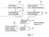
- the data processing system 11 of FIG. 1 comprises a first sensor 10 coupled to a first reference frame manager 12 and a second sensor 14 coupled to a second reference frame manager 16.
- the first reference frame manager 12 communicates to an integration module 18;
- the second reference frame manager 16 communicates to the integration module 18.
- the integration module 18 and a motion detector 22 provide input data to an update module 20.
- the data processing system 11 is associated with or mounted on a vehicle.
- the first sensor 10 comprises a radar system
- the second sensor 14 comprises an ultrasonic system
- the first sensor 10, the second sensor 14, or both may comprise any suitable distance sensor or range finder.
- the first sensor 10 and the second sensor 14 each provide a data output or an output signal that is indicative of the distance (e.g., range) between the sensor (e.g., mounted on the vehicle) and a reflective object or obstacle.
- the first sensor 10 and the second sensor 14 may provide an orientation or azimuth associated with the distance of the obstacle with respect to the vehicle.
- a control system or obstacle avoidance system can use the output data or signals of the data processing system 11 to avoid colliding with obstacles at certain distances and azimuths from the vehicle, for example.
- the first sensor 10 and the second sensor 14 may each transmit a pulse at a transmission time.
- a reflected pulse may be reflected from a surface of an obstacle or obstruction and received at the first sensor 10, the second sensor 14, or both for processing at a reception time.
- An elapsed time between the transmission time of the transmission pulse and the reception time of the reflected pulse may be used to estimate the distance or range between the object and the vehicle because the elapsed time is proportional to the distance.
- Electromagnetic propagation generally propagates at approximately the speed of light.
- the radar system may have a radar range and an associated radar beam width.
- the ultrasonic system may have a ultrasonic range and an associated ultrasonic beam width.
- the radar range may be defined in terms of a maximum range or distance to a detectable obstacle (e.g., of minimum size and reflectivity), a minimum range or distance to an obstacle, or an azimuth range with respect to the obstacle.
- the ultrasonic range may be defined in terms of a maximum range or distance to a detectable obstacle (e.g., of minimum size and reflectivity), a minimum range to a detectable obstacle, or an azimuth range with respect to the obstacle.
- the radar beam width and the ultrasonic beam width may be defined in terms of degrees, for example, or a half power beam width.
- the first reference frame manager 12 may comprise data storage for collecting and organizing each first group of first sensor readings associated with a corresponding time interval.
- the first sensor 10 collects a first group of sensor readings at regular time intervals. Each first group of the sensor readings may be identified by a unique time interval or time stamp for subsequent processing and retrieval.
- the first group may be modeled as virtual grid of cells, where each cell corresponds to a two or three dimensional spatial location (or location range) around the vehicle, the first group of readings may be organized as sets of coordinates (e.g., two or three dimensional coordinates) and associated readings (e.g., reflectivity, signal strength, or elapsed time).
- the second reference frame manager 16 may comprise data storage for collecting and organizing each first group of second sensor 14 readings associated with a corresponding time interval.
- the second sensor 14 collects a first group of sensor readings at regular time intervals.
- Each second group of the sensor readings may be identified by a unique time interval or time stamp for subsequent processing and retrieval.
- the second group may be modeled as virtual grid of cells, where each cell corresponds to a two or three dimensional spatial location (or location range) around the vehicle, the second group of readings may be organized as sets of coordinates (e.g., two or three dimensional coordinates) and associated readings (e.g., reflectivity, signal strength, or elapsed time).
- the integration module 18 generally spatially and temporally aligns the first group of sensor readings and the second group of sensor readings to determine a composite grid.
- the composite grid is referenced to a ground reference frame.
- the composite grid or a precursor to the composite grid may be referenced to a vehicle coordinate reference frame.
- the composite grid may be divided into cells, two-dimensional cells, cubic cells, or columns and rows.
- a cell shall refer to a two-dimensional cell or a three-dimensional cell that is associated with a composite grid.
- Each cell in the composite grid has a state.
- each cell may have unoccupied state, an occupied state, a probability of occupancy, and a probability of nonoccupancy.
- a cell may have a state that represents occupancy, traversability, emptiness, or another binary random variable important for vehicle path planning, safety, trajectory control, speed, velocity, or acceleration.
- An unoccupied states means that the cell is not occupied by a detected obstacle.
- the occupied states means that the cell is occupied by a detected obstacle.
- the probability of occupancy defines a likelihood that the a given cell is occupied by an obstacle.
- the probability level may be expressed as a percentage value from zero percent to 100 percent, or otherwise.
- the update module 20 may update or refresh the grid on a regular basis or upon material movement of the vehicle.
- the update module 20 may refresh the composite grid upon material movement of the vehicle such that the overall state (e.g., occupancy or probability of occupancy) of each cell in the grid varies in accordance with the particular location (e.g., and heading) of the vehicle in the environment.
- the motion detector 22 may provide a relative displacement (e.g., vectors or coordinates associated with corresponding measurement times) over a certain time interval to facilitate an update of the grid.
- the motion detector 22 may comprise one or more of the following: a location-determining receiver (e.g., a Global Positioning System (GPS) receiver), a GPS receiver with differential correction, an odometer, an accelerometer, a dead-reckoning positioning system, a radio frequency positioning system, a laser positioning system, and an optical positioning system.
- the location-determining receiver may output position data (e.g., geographic coordinates associated with corresponding measurement times, velocity vector data, or both). Velocity vector data may refer to speed and heading data.
- the motion detector 22 may determine the relative displacement of the occupancy detector based on a velocity, speed, or acceleration of the vehicle.
- the dead-reckoning system may comprise the combination of a displacement sensor and a heading sensor.
- the displacement sensor measures the relative displacement of the vehicle, whereas the heading sensor measures the relative heading.
- the dead-reckoning system may output a traveled distance of the vehicle, a traveled direction of the vehicle, traveled distance versus time (e.g., vehicular speed), or vehicular velocity (e.g., speed and heading).
- the dead-reckoning system comprises (1) an odometer or wheel revolution counter as the displacement sensor and (2) a gyroscope as the heading sensor.
- the odometer or wheel revolution counter may directly or indirectly count vehicular wheel revolutions or fractions thereof.
- the gyroscope may provide vehicle direction information or heading information.
- output of an accelerometer may be double-integrated to determine relative displacement of the vehicle, for example.
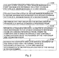
- FIG. 2 describes a method of conducting sensor fusion to facilitate vehicular guidance. The method of FIG. 2 begins in step S100.
- a first sensor 10 collects a first group of first sensor 10 readings of a first size.
- the first size may be dependent upon a maximum range of the first sensor 10, a coverage pattern of the first sensor 10, or safeguarding requirements of a vehicle.
- the range or coverage pattern of the first sensor 10 may be selected based on the safeguarding requirements of the vehicle, its maximum operational velocity, and other factors.
- the first sensor 10 readings are initially referenced to the orientation and position of the first sensor 10 on the vehicle.
- the first sensor 10 may collect a first group of first sensor readings (e.g., range and azimuth of various objects or obstacles in the coverage pattern) at regular intervals (e.g., sampling rate or periodic interval).
- a second sensor 14 collects a second group of second sensor 14 readings of a second size.
- the second size may be dependent upon a maximum range of the second sensor 14, a coverage pattern of the second sensor 14, or safeguarding requirements of a vehicle.
- the range or coverage pattern of the second sensor 14 may be selected based on the safeguarding requirements of the vehicle, its maximum operational velocity, and other factors.
- the second sensor 14 readings are initially referenced to the orientation and position of the second sensor 14 on the vehicle.
- the second sensor 14 may collect a first group of first sensor readings (e.g., range and azimuth of various objects or obstacles in the coverage pattern) at regular intervals (e.g., sampling rate or periodic interval).
- the first reference frame manager 12 and the second reference frame manager 16 reference the first group and the second group of readings to a vehicle coordinate reference frame.
- the first reference frame manager 12 may apply a first offset (e.g., two dimensional or three dimensional) or first correction factor that aligns the particular position and orientation of first sensor 10 to the vehicle coordinate reference frame.
- the second reference frame manager 16 may apply a second offset (e.g., two dimensional or three dimensional) or second correction factor that aligns the particular position and orientation of second sensor 14 to the vehicle coordinate reference frame.
- the integration module 18 establishes a composite grid referenced to the vehicle coordinate system or to ground (e.g., ground reference coordinates or absolute coordinates) based on a spatially and temporally aligned integration of the readings of the first group and the second group.
- the integration module 18 may integrate the first group and the second group of readings in accordance with a conditional probability approach, a Bayes rule approach, or a variation thereof.
- each cell of a composite grid may be defined as the occurrence of a first event (e.g., an obstacle is present) associated with first sensor readings and the probability of occurrence (e.g., a certain percentage chance that an obstacle is present) of a second event associated with second sensor readings.
- the first sensor readings may define a first virtual grid or matrix
- the second sensor readings may define a second virtual grid or matrix that can be temporally and spatially aligned with the first virtual grid for formation of the composite grid.
- step S106 the combination of information from different sensors and from various perspectives can help to avoid the susceptibility of generally wide sensor beams to noise and clutter.
- the integration module 18 considers the relative displacement or motion between the different measurements.
- the composite grid does not represent a global map with size dependent on the size of the work area, but rather a grid of limited size (e.g., local grid) that depends on the sensor range and safeguarding requirements.
- the size of the grid is based on the range and coverage of the first sensor 10 and the second sensor 14.
- the update module 20 refreshes or updates the composite grid upon material movement of the vehicle such that the overall state (e.g., occupancy) of each cell in the composite grid varies in accordance with the particular location of the vehicle in the environment. For example, the update module 20 refreshes the grid upon the sooner of material movement of the vehicle or a regular update interval.
- the regular update interval is used such that the vehicle can quickly recognize changes in the environment that might be caused by movement of obstacles or movement of new obstacles into the work area.
- the contents of the composite grid depend upon the vehicle position or orientation, and vary with changes in the vehicle position or orientation.
- the composite grid is referenced to the vehicle coordinate frame and remains stationary with respect to the vehicle coordinate frame at all times. However, the cell content of the composite grid is referenced to the ground.
- the composite grid scrolls the values of the cells in such a way that the cell value keeps representing the occupancy (or another metric) of that particular position of the vehicle on the terrain. Accordingly, the scrolling of the values facilitates integration of sensor data that is position coherent. In the case of vehicle rotation, or an azimuth shift the cell contents of the grid move from the original cell to the new cell representing the particular position.
- the update module 20 may refresh the values of composite grid (e.g., even from a stationary location) for the regular update interval (e.g., periodically) as frequently as a sampling rate of the first sensor 10, the second sensor 14, or both permit.
- the update module may include, but need not include, a filter (e.g., a Bayes rule filter) that filters the values of the composite grid over time to reduce errors, and artifacts that otherwise might be present.
- Bayes rules defines a conditional probability that involves the occurrence of a first event and the probability of occurrence of a second event. Accordingly, the Bayes filter may be used to filter out or manipulate anomalous data that is inconsistent with a conditional probability relationship or historical patterns.
- the vehicle controller or vehicle data processing system can traverse obstacle-free areas or cells and avoid obstacle-enriched areas or cells. Accordingly, a path planning system or vehicle data processing system may use the grid for planning vehicle trajectory of unmanned vehicles or to aid driver operations for a manned vehicle.
- step S108 is replaced by steps S107, S110, and S112.
- Like reference numbers in FIG. 2 and FIG. 3 indicate like steps or procedures.
- a data processing system 11 or update module 20 determines whether a location determining receiver (e.g., a Global Positioning System Receiver with differential correction) detects a material movement (e.g., receive signals or received data on vehicular position versus time) of the vehicle with a desired degree of reliability.
- the material movement may comprise a distance or displacement vector that is a difference between starting coordinates of the vehicle and termination coordinates of the vehicle during an evaluation time period, where the difference is greater than or equal to some threshold.
- the threshold or material movement may be greater than or equal to a user defined measurement (e.g., .1 meters) or to some faction of cell width, cell height or another cell dimension.
- the reliability of the detection of material movement or position may be expressed as a Dilution of Precision (DOP), a signal quality level of one or more received signals (e.g., satellite downlink signals) at the location-determining receiver, a signal strength level of one or more received signals (e.g., satellite downlink signals) at the location-determining receiver, or a bit error rate, symbol error rate or frame error rate of one or more received signals at the location-determining receiver, or the availability or unavailability of the location-determining receiver.
- DOP Dilution of Precision
- Dilution of Precision is a representation (e.g., figure of merit) of the quality of a position data (e.g., GPS position data) which considers the relative locations of satellites and their geometric relationship to the location-determining receiver.
- the DOP may consider the number of satellites that are available (e.g., capable of being received with a reliable signal strength, a signal quality level, a maximum bit or symbol error rate) to a location-determining receiver from particular geographic coordinates of the location-determining receiver at a given time.
- DOP may generally refer to any of the following: Position Dilution of Precision, Relative Dilution of Precision, Horizontal Dilution of Precision, Vertical Dilution of Precision, Time Dilution of Precision, and Geometric Dilution of Precision.
- Position Dilution of Precision refers to a DOP value for the particular three dimensional coordinates that indicates errors in satellite position and the errors in the location-determining receiver position.
- Relative Dilution of Precision provides an indication of the adequacy of observations of a location determining receiver during real-time surveying of measurements.
- Horizontal Dilution of Precision refers to DOP with respect to latitude and longitude measurements.
- Vertical dilution of precision refers to DOP with respect to height.
- Time Dilution of Precision refers to DOP with respect to temporal variations.
- the location-determining receiver is detecting a material movement of the vehicle, the location-determining receiver should be sufficiently reliable during the period of the movement. If the location-determining receiver meets or exceeds a desired degree of reliability for detection of a material movement or position data of the vehicle, the method continues with step S110. However, if the location-determining receiver does not meet the desired degree of reliability for detection of a material movement or position data of the vehicle, the method continues with step S112.
- the update module 20 refreshes the composite grid upon material movement of the vehicle detected by the location-determining receiver (e.g., Global Positioning Receiver with differential correction), such that the overall state (e.g., occupancy) of each cell in the grid varies in accordance with the particular location of the vehicle in the environment.
- the update module 20 refreshes the composite grid upon the expiration of a time interval (e.g., a regular time interval) or upon material movement of the vehicle, whichever occurs first; where the material movement is detected by the location-determining receiver (e.g., Global Positioning Receiver with differential correction), such that the overall state (e.g., occupancy) of each cell in the grid varies in accordance with the particular location of the vehicle in the environment.
- a time interval e.g., a regular time interval
- the location-determining receiver e.g., Global Positioning Receiver with differential correction
- the refreshing or updating of the composite grid in step S110 may be carried out in accordance with various techniques, which may be applied alternately or cumulatively.
- the material movement of the vehicle may be used to generate a new composite grid based on a new sample, a next sample, a new scan, a next scan, or updated collection of the first group of first sensor readings, the second group of second sensor readings, or both.
- the coverage area of the first sensor and the seconds sensor extend beyond the first composite grid and the data storage device associated with the integration module or update module allows updating without collection of new data.
- At least one of the update module 20, the first sensor 10, and the second sensor 14 determines the an update interval or an elapsed time period since the last update or sample time for collecting a first group of first sensor data and a second group of second sensor data.
- the update module 20 refreshes the composite grid upon material movement of the vehicle detected by at least one of an odometer, a dead-reckoning system, and an accelerometer, such that the overall state (e.g., occupancy) of each cell in the grid varies in accordance with the particular location of the vehicle in the environment.
- the material movement may comprise a distance or displacement vector that is a difference between starting coordinates of the vehicle and termination coordinates of the vehicle during an evaluation time period, where the difference is greater than or equal to some threshold.
- the threshold or material movement may be greater than or equal to a user defined measurement (e.g., .1 meters) or to some faction of cell width, cell height or another cell dimension.
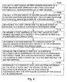
- step S106 of FIG. 4 is replaced by step S114, S116, and S118.
- step S114, S116, and S118 Like reference numbers indicate like method or procedures.
- an integration module 18 or a mapper determines a first mapping of the first group of first sensor 10 readings with respect to a composite grid (e.g., a composite occupancy grid). For example, upon initialization of the data processing system 11, including the integration module 18, the integration module 18 may determine the first mapping of the first group of first sensor readings with respect to the composite grid. By determining the first mapping in advance or upon initialization, the data processing or computation resources of the integration module 18 or data processing system 11 are fully available or less taxed for other data processing tasks associated with sensor fusion during operation of the vehicle.
- a composite grid e.g., a composite occupancy grid
- an integration module 18 a mapper determines a second mapping of the second group of second sensor 14 readings with respect to a composite grid (e.g., a composite occupancy grid). For example, upon initialization of the data processing system 11, including the integration module 18, the integration module 18 may determine the second mapping of the second group of second sensor readings with respect to the composite grid. By determining the second mapping in advance or upon initialization, the data processing or computation resources of the integration module 18 or data processing system 11 are fully available or less taxed for other data processing tasks associated with sensor fusion during operation of the vehicle.
- a composite grid e.g., a composite occupancy grid
- an integration module 18 establishes a composite grid (e.g., a composite occupancy grid) referenced to the vehicle coordinate reference frame or a ground reference frame, where the composite grid is based on the first mapping and the second mapping.
- a composite grid e.g., a composite occupancy grid
- step S108 may follow step S118.
- the update module 20 refreshes the composite grid upon material movement of the vehicle such that the overall state (e.g., occupancy) of each cell in the grid varies in accordance with the particular location of the vehicle in the environment.
- the system 11 of FIG. 5 is similar to the data processing system 11 of FIG. 1 , except the data processing system 11 of FIG. 5 further comprises a guidance module 24 coupled to the update module 20.
- the guidance module 24 may communicate with one or more of the following via a one or more logical or physical data paths: a steering system 26, a propulsion system 28, and a braking system 30.
- a physical data path may comprise a transmission line, or a databus, for example.
- the guidance module 24 may generate control signals for the steering system 26 , a braking system 30, and a propulsion system 28 that are consistent with the composite grid or occupancy states with the composite grid.
- the control signals may comprise a steering control signal or data message that is time dependent and defines a steering angle of the steering shaft; a braking control signal or data message that defines the amount of deceleration, hydraulic pressure, or braking friction applied to brakes; a propulsion control signal or data message that controls a throttle setting, a fuel flow, a fuel injection system, vehicular speed or vehicular acceleration. If the vehicle is propelled by an electric drive or motor, the propulsion control signal or data message may control electrical energy, electrical current, or electrical voltage to the electric drive or motor.
- the steering system 26 may comprise an electrically controlled hydraulic steering system, an electrically driven rack-and-pinion steering, an Ackerman steering system, or another steering system.
- the braking system 30 may comprise an electrically controlled hydraulic braking system, or another electrically controlled friction braking system.
- the propulsion system 28 may comprise an internal combustion engine, an internal combustion engine- electric hybrid system, an electric drive system, or the like.
- FIG. 6 The method of FIG. 6 is similar to the method of FIG. 1 , except step S109 is added.
- Like reference numbers indicate like procedures or steps in FIG. 1 and FIG. 6 .
- Step S109 follows step S108.
- a guidance module 24 determines a guidance plan (e.g., guidance vector) of the vehicle based on the composite grid (e.g., detected positions of obstacles in the composite grid).
- the guidance plan may avoid approaching an obstacle or a zone around the obstacle.
- the guidance module 24 establishes a plan that prohibits the vehicle from entering into cells occupied by the obstacle.
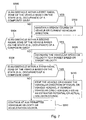
- FIG. 7 provides a guidance plan of the vehicle that may be applied to any of the composite grids formed in accordance with any embodiments disclosed herein.
- the method of FIG. 7 may be regarded as an illustrative example for carrying out step S109 of FIG. 6 .
- a guidance module 24 determines if an obstacle is within a first radial zone of the vehicle based on the state (e.g., occupancy) of a composite grid.
- the first radial zone may extend between an outer radius and an intermediate radius. If the obstacle is present within the first radial zone, the method continues with step S502. However, if the obstacle is not present within the first radial zone, the method continues with step S504.
- the guidance module 24 maintains a steady course or the current vehicle direction, at least until the next update of the composite grid.
- the maintenance of a steady course may include maintaining a current velocity and heading, for instance.
- the vehicle may change direction velocity or acceleration because of the preference of an operator, as opposed to the presence of an obstacle.
- the obstacle in the first radial zone is so far away from the vehicle that it poses virtually no risk of collision, imminent threat, or immediate interaction with the obstacle.
- a guidance module 24 determines if an obstacle is within a second radial zone of the vehicle based on the state (e.g., occupancy) of the composite grid.
- the second radial zone may extend between an intermediate radius and an inner radius. If the obstacle is present within the second radial zone, the method continues with step S506. However, if the obstacle is not present within the second radial zone, the method continues with step S508.
- the guidance module 24 decreases the vehicular speed or velocity to a target speed or target velocity, or below the target speed or target velocity.
- the target speed or target velocity may be based on maintaining a desired degree of separation between the vehicle and the obstacle.
- the guidance module 24 may send a command to the propulsion system 28, the braking system 30, or both to reduce the vehicular speed or velocity.
- a guidance module 24 determines if an obstacle is within a third radial zone of the vehicle based on the state (e.g., occupancy) of the composite grid.
- the third radial zone extends between an inner radius and approximately zero radius from the vehicle. If the obstacle is present within the third radial zone, the method continues with step S510. However, if the obstacle is not present within the third radial zone, the method continues with step S512.
- the guidance module 24 stops the vehicle or changes the vehicular direction of travel or the vehicle heading to avoid a collision with the obstacle or to otherwise meet safety objectives. For example, if the current vehicular direction qualifies as an estimated potential or actual collision course with the obstacle in the third radial zone, the guidance module 24 may institute any appropriate evasive measure, including stopping the vehicle, turning the vehicle, or both. The guidance module 24 may command the braking system 30 to apply maximum braking power or force or to even reverse thrust of the propulsion system 28 to slow or stop the vehicle in step S510.
- step S512 the vehicle continues at any permitted vehicular velocity or acceleration vector.
- FIG. 8 represents the implementation of a composite grid 750 for sensor fusion.
- FIG. 8 shows a plan view of the first vehicle 702 associated with a composite grid within a global grid 751.
- the global grid 751 has a first depth 753 and first width 754.
- the composite grid 750 has a second depth 761 and a second width 762, which are less than or equal to the first depth 753 and the first width 754.
- a first vehicle 702 is present in the center of the global grid 751 and is moving upwards toward an obstacle 712 (e.g. a second vehicle).
- the first vehicle 702 has a data processing system 11 that transmits pulses or other electromagnetic radiation in a sensor coverage pattern 710 or radiation pattern.
- the transmitted pulses are reflected by the obstacle 712.
- the reflection of the transmitted pulse from the vehicle is processed by an algorithm (e.g., a sensor-specific algorithm) in the data processing system 11 to update the values of the composite grid cells 700 in the beam width of the sensor(s) (e.g., 10 and 14).
- the difference between the transmission time of propagation of the transmitted pulse and the reception time of the reflected pulse is used to estimate the distance of the obstacle 712 with respect to the first vehicle 702.
- the composite grid illustrates the occupied cells for a first scan as shaded in FIG. 8 .
- the circles around the first vehicle 702 define the boundaries or perimeters of areas or zones of sensitivity to the presence of obstacles (e.g., 712).
- a first radial zone 704 is defined or bounded by an outer radius 701 and an intermediate radius 703.
- a second radial zone 706 is defined by or bounded by an intermediate radius 703 and an inner radius 705.
- a third radial zone 708 is defined by or bounded by an inner radius 705 and a substantially zero radius about the vehicle.
- the obstacle 712 may cause no change in the path of vehicle, because the guidance module 24 estimates that a collision course is impossible within an evaluation time period given the position, velocity and acceleration of the vehicle, and an estimated position, maximum velocity, and maximum acceleration of the obstacle. If an obstacle 712 is present in the second radial zone 706 in accordance with the composite grid, the guidance module 24 may instruct the propulsion system 28 or the braking system 30 to slow the vehicle or reduce its velocity. If an obstacle 712 is present in the third radial zone 708, in accordance with the composite grid, the guidance module 24 may instruct the propulsion system 28 and the braking system 30 to stop the vehicle.
- the steps may be executed in any suitable order.
- the third radial zone 708 may be considered first to provide more processing time than might otherwise be allotted.
- the use of the composite grid for the fusion and integration of sensor data presents advantages in several areas.
- the first sensor 10 readings and the second sensor 14 readings may be spatially and temporally aligned and integrated with reference to the vehicle coordinate frame, as opposed to the ground or another coordinate frame.
- Many vehicles may rely on odometry for short term relative positioning. This generally suffices to meet the positioning and orientation requirements to keep the composite grid map up to date.
Landscapes
- Engineering & Computer Science (AREA)
- Radar, Positioning & Navigation (AREA)
- Remote Sensing (AREA)
- Physics & Mathematics (AREA)
- General Physics & Mathematics (AREA)
- Computer Networks & Wireless Communication (AREA)
- Aviation & Aerospace Engineering (AREA)
- Automation & Control Theory (AREA)
- Traffic Control Systems (AREA)
Claims (12)
- Verfahren zum Durchführen von Sensorfusion zum Detektieren der Anwesenheit oder Abwesenheit von Hindernissen um ein Fahrzeug (702) herum, wobei das Verfahren Folgendes umfasst:Sammeln einer ersten Gruppe von Ablesungen einer ersten Größe von einem ersten Sensor (10) zum Detektieren der Distanz zwischen dem ersten Sensor (10), der an dem Fahrzeug (702) angebracht ist, und einem Objekt oder Hindernis;Sammeln einer zweiten Gruppe von Ablesungen einer zweiten Größe von einem zweiten Sensor (14) zum Detektieren der Distanz zwischen dem zweiten Sensor (14), der an dem Fahrzeug (702) angebracht ist, und einem Objekt oder Hindernis;Beziehen der ersten Gruppe und der zweiten Gruppe von Ablesungen auf ein Fahrzeug-Koordinatenbezugssystem;Herstellen eines Verbundgitters, das auf das Fahrzeug-Koordinatenbezugssystem oder den Boden bezogen ist, wobei das Verbundgitter auf einer räumlich und zeitlich ausgerichteten Integration der Ablesungen der ersten Gruppe und der zweiten Gruppe basiert; undAuffrischen des Verbundgitters beim Baldigeren einer materiellen Bewegung des Fahrzeugs (702) dergestalt, dass der Gesamtzustand jeder Zelle in dem Verbundgitter gemäß dem bestimmten Ort des Fahrzeugs (702) in der Umgebung variiert, oder einem regelmäßigen Aktualisierungsintervall.
- Verfahren nach Anspruch 1, wobei das Verbundgitter ein Verbundbesetzungsgitter umfasst und wobei der Gesamtzustand mindestens eine der folgenden Alternativen umfasst: einen besetzten Zustand, einen unbesetzten Zustand, eine Wahrscheinlichkeit der Besetzung und eine Wahrscheinlichkeit der Nichtbesetzung.
- Verfahren nach Anspruch 2, ferner umfassend:Bestimmen eines Führungsplans auf der Basis der Anwesenheit eines oder mehrerer Hindernisse gemäß dem Verbundgitter.
- Verfahren nach Anspruch 1, ferner umfassend:Bestimmen, ob materielle Bewegung des Fahrzeugs durch einen ortsbestimmenden Empfänger mit einem gewünschten Zuverlässigkeitsgrad detektiert wird; undAuffrischen des Verbundgitters gemäß der durch den ortsbestimmenden Empfänger detektierten materiellen Bewegung, wenn Positionsdaten des ortsbestimmenden Empfängers einen gewünschten Zuverlässigkeitsgrad erreichen oder übersteigen.
- Verfahren nach Anspruch 1, ferner umfassend:Bestimmen, ob materielle Bewegung des Fahrzeugs durch einen ortsbestimmenden Empfänger mit einem gewünschten Zuverlässigkeitsgrad detektiert wird; undAuffrischen des Verbundgitters gemäß der materiellen Bewegung, die durch mindestens eine der Alternativen eines Wegmessers, eines Koppelnavigationssystems und eines Beschleunigungsmessers detektiert wird, wenn Positionsdaten des ortsbestimmenden Empfängers einen gewünschten Zuverlässigkeitsgrad nicht erreichen.
- Verfahren nach Anspruch 1, wobei das Herstellen ferner Folgendes umfasst:Bestimmen einer ersten Abbildung der ersten Gruppe von ersten Sensorablesungen mit Bezug auf das Verbundbesetzungsgitter;Bestimmen einer zweiten Abbildung der zweiten Gruppe von zweiten Sensorablesungen mit Bezug auf das Verbundbesetzungsgitter; undHerstellen eines Verbundgitterbezugs auf das Fahrzeug-Koordinatenbezugssystem oder ein Bodenbezugssystem, wobei das Verbundgitter auf der ersten Abbildung und der zweiten Abbildung basiert.
- Verfahren nach Anspruch 6, wobei die erste Abbildung und die zweite Abbildung während der Initialisierung eines Datenverarbeitungssystems bestimmt werden.
- Verfahren nach Anspruch 1, ferner umfassend:Aufrechterhalten des aktuellen Fahrzeugkurses, wenn auf der Basis des Verbundgitters ein Hindernis in einer ersten radialen Zone anwesend ist.
- Verfahren nach Anspruch 8, ferner umfassend:Verringern einer Fahrzeuggeschwindigkeit oder eines Geschwindigkeitsvektors des Fahrzeugs auf eine Zielgeschwindigkeit oder einen Zielgeschwindigkeitsvektor, wenn auf der Basis des Verbundgitters ein Hindernis in einer mit dem Fahrzeug assoziierten zweiten radialen Zone anwesend ist.
- Verfahren nach Anspruch 9, ferner umfassend:Stoppen der Bewegung des Fahrzeugs, wenn auf der Basis des Verbundgitters ein Hindernis in einer mit dem Fahrzeug assoziierten dritten radialen Zone anwesend ist oder sich eine aktuelle Fahrzeugrichtung als tatsächlicher oder potentieller Kollisionskurs mit dem Hindernis qualifiziert.
- System zum Durchführen von Sensorfusion, das dafür ausgelegt ist, gemäß dem Verfahren nach einem der vorhergehenden Ansprüche zu operieren.
- Fahrzeug (702) mit einem System nach Anspruch 11.
Applications Claiming Priority (1)
| Application Number | Priority Date | Filing Date | Title |
|---|---|---|---|
| US11/158,546 US7266477B2 (en) | 2005-06-22 | 2005-06-22 | Method and system for sensor signal fusion |
Publications (2)
| Publication Number | Publication Date |
|---|---|
| EP1742083A1 EP1742083A1 (de) | 2007-01-10 |
| EP1742083B1 true EP1742083B1 (de) | 2013-01-02 |
Family
ID=36956184
Family Applications (1)
| Application Number | Title | Priority Date | Filing Date |
|---|---|---|---|
| EP06115352A Ceased EP1742083B1 (de) | 2005-06-22 | 2006-06-13 | Verfahren und System zur Sensorsignalfusion |
Country Status (2)
| Country | Link |
|---|---|
| US (1) | US7266477B2 (de) |
| EP (1) | EP1742083B1 (de) |
Cited By (7)
| Publication number | Priority date | Publication date | Assignee | Title |
|---|---|---|---|---|
| US9316737B2 (en) | 2012-11-05 | 2016-04-19 | Spireon, Inc. | Container verification through an electrical receptacle and plug associated with a container and a transport vehicle of an intermodal freight transport system |
| US9551788B2 (en) | 2015-03-24 | 2017-01-24 | Jim Epler | Fleet pan to provide measurement and location of a stored transport item while maximizing space in an interior cavity of a trailer |
| US9779449B2 (en) | 2013-08-30 | 2017-10-03 | Spireon, Inc. | Veracity determination through comparison of a geospatial location of a vehicle with a provided data |
| US9779379B2 (en) | 2012-11-05 | 2017-10-03 | Spireon, Inc. | Container verification through an electrical receptacle and plug associated with a container and a transport vehicle of an intermodal freight transport system |
| US10169822B2 (en) | 2011-12-02 | 2019-01-01 | Spireon, Inc. | Insurance rate optimization through driver behavior monitoring |
| US10223744B2 (en) | 2013-12-31 | 2019-03-05 | Spireon, Inc. | Location and event capture circuitry to facilitate remote vehicle location predictive modeling when global positioning is unavailable |
| US10255824B2 (en) | 2011-12-02 | 2019-04-09 | Spireon, Inc. | Geospatial data based assessment of driver behavior |
Families Citing this family (112)
| Publication number | Priority date | Publication date | Assignee | Title |
|---|---|---|---|---|
| US10809071B2 (en) | 2017-10-17 | 2020-10-20 | AI Incorporated | Method for constructing a map while performing work |
| US7453395B2 (en) * | 2005-06-10 | 2008-11-18 | Honeywell International Inc. | Methods and systems using relative sensing to locate targets |
| US7518713B2 (en) * | 2005-11-08 | 2009-04-14 | Honeywell International Inc. | Passive-optical locator |
| US20070127008A1 (en) * | 2005-11-08 | 2007-06-07 | Honeywell International Inc. | Passive-optical locator |
| US20070103671A1 (en) * | 2005-11-08 | 2007-05-10 | Honeywell International Inc. | Passive-optical locator |
| US20090157566A1 (en) * | 2006-03-21 | 2009-06-18 | Bernard Grush | Method and process to ensure that a vehicular travel path recording that includes positional errors can be used to determine a reliable and repeatable road user charge |
| CN101449306B (zh) * | 2006-03-21 | 2011-11-02 | 天米公司 | 隐私的和可审计的车辆定位系统及用于该系统的机载设备 |
| US7920962B2 (en) * | 2006-06-19 | 2011-04-05 | Kiva Systems, Inc. | System and method for coordinating movement of mobile drive units |
| CA2860745C (en) * | 2006-09-14 | 2016-03-08 | Crown Equipment Corporation | Associating a transmitter and a receiver in a supplemental remote control system for materials handling vehicles |
| US9122276B2 (en) | 2006-09-14 | 2015-09-01 | Crown Equipment Corporation | Wearable wireless remote control device for use with a materials handling vehicle |
| US8452464B2 (en) * | 2009-08-18 | 2013-05-28 | Crown Equipment Corporation | Steer correction for a remotely operated materials handling vehicle |
| US9207673B2 (en) * | 2008-12-04 | 2015-12-08 | Crown Equipment Corporation | Finger-mounted apparatus for remotely controlling a materials handling vehicle |
| US8970363B2 (en) | 2006-09-14 | 2015-03-03 | Crown Equipment Corporation | Wrist/arm/hand mounted device for remotely controlling a materials handling vehicle |
| US9645968B2 (en) * | 2006-09-14 | 2017-05-09 | Crown Equipment Corporation | Multiple zone sensing for materials handling vehicles |
| US20080082254A1 (en) * | 2006-10-02 | 2008-04-03 | Yka Huhtala | Route-assisted GPS location sensing via mobile device |
| US7653513B2 (en) * | 2007-06-20 | 2010-01-26 | At&T Intellectual Property Ii, L.P. | Sensor registration by global optimization procedures |
| US20090002677A1 (en) * | 2007-06-26 | 2009-01-01 | Honeywell International Inc. | Target locator system |
| US8135518B2 (en) | 2007-09-28 | 2012-03-13 | Caterpillar Inc. | Linkage control system with position estimator backup |
| JP4658155B2 (ja) * | 2008-03-17 | 2011-03-23 | 株式会社日立製作所 | 自律移動ロボット装置及び自律移動ロボット装置の回避方法 |
| US8989972B2 (en) | 2008-09-11 | 2015-03-24 | Deere & Company | Leader-follower fully-autonomous vehicle with operator on side |
| US8478493B2 (en) * | 2008-09-11 | 2013-07-02 | Deere & Company | High integrity perception program |
| US8224500B2 (en) * | 2008-09-11 | 2012-07-17 | Deere & Company | Distributed knowledge base program for vehicular localization and work-site management |
| US8195358B2 (en) | 2008-09-11 | 2012-06-05 | Deere & Company | Multi-vehicle high integrity perception |
| US8195342B2 (en) * | 2008-09-11 | 2012-06-05 | Deere & Company | Distributed knowledge base for vehicular localization and work-site management |
| US9188980B2 (en) * | 2008-09-11 | 2015-11-17 | Deere & Company | Vehicle with high integrity perception system |
| US9235214B2 (en) * | 2008-09-11 | 2016-01-12 | Deere & Company | Distributed knowledge base method for vehicular localization and work-site management |
| US20100063652A1 (en) * | 2008-09-11 | 2010-03-11 | Noel Wayne Anderson | Garment for Use Near Autonomous Machines |
| US8818567B2 (en) * | 2008-09-11 | 2014-08-26 | Deere & Company | High integrity perception for machine localization and safeguarding |
| US8392065B2 (en) * | 2008-09-11 | 2013-03-05 | Deere & Company | Leader-follower semi-autonomous vehicle with operator on side |
| US9026315B2 (en) | 2010-10-13 | 2015-05-05 | Deere & Company | Apparatus for machine coordination which maintains line-of-site contact |
| US8229618B2 (en) * | 2008-09-11 | 2012-07-24 | Deere & Company | Leader-follower fully autonomous vehicle with operator on side |
| FR2938960B1 (fr) * | 2008-11-25 | 2010-11-12 | Thales Sa | Procede de transmission d'une coordonnee geographique. |
| US9522817B2 (en) | 2008-12-04 | 2016-12-20 | Crown Equipment Corporation | Sensor configuration for a materials handling vehicle |
| US9075145B2 (en) | 2009-05-12 | 2015-07-07 | Raytheon Anschutz Gmbh | Combining data from multiple radar signals on a single plan position indicator (PPI) display |
| TWI411803B (zh) * | 2009-05-19 | 2013-10-11 | Univ Nat Taiwan | 室內目標定位裝置及方法 |
| US8577551B2 (en) | 2009-08-18 | 2013-11-05 | Crown Equipment Corporation | Steer control maneuvers for materials handling vehicles |
| US8731777B2 (en) | 2009-08-18 | 2014-05-20 | Crown Equipment Corporation | Object tracking and steer maneuvers for materials handling vehicles |
| KR101302134B1 (ko) * | 2009-12-18 | 2013-08-30 | 한국전자통신연구원 | 복합 센서정보 제공 장치 및 방법 |
| JP5206752B2 (ja) * | 2010-08-30 | 2013-06-12 | 株式会社デンソー | 走行環境認識装置 |
| KR20120043446A (ko) * | 2010-10-26 | 2012-05-04 | 한국전자통신연구원 | 차량 및 장애물의 위치 검출 장치 및 그 방법 |
| US9737353B2 (en) | 2010-12-16 | 2017-08-22 | Biosense Webster (Israel) Ltd. | System for controlling tissue ablation using temperature sensors |
| US8544574B2 (en) | 2011-07-20 | 2013-10-01 | Deere & Company | Grain cart capable of self-propulsion |
| JP5953677B2 (ja) * | 2011-08-30 | 2016-07-20 | ソニー株式会社 | 情報処理装置、情報処理方法、プログラム、及び記録媒体 |
| US8868344B2 (en) * | 2011-09-22 | 2014-10-21 | Honeywell International Inc. | Systems and methods for combining a priori data with sensor data |
| US20130079979A1 (en) * | 2011-09-23 | 2013-03-28 | Alan D. Sheidler | Towed vehicle arrangement responsive to lateral hitch loading |
| US9037346B2 (en) * | 2011-09-23 | 2015-05-19 | Deere & Company | Steering control for vehicle trains |
| KR101316501B1 (ko) * | 2011-10-14 | 2013-10-10 | 현대자동차주식회사 | 메쉬형 공간 해석기법을 이용한 주차 공간 탐지방법 및 그 시스템 |
| US9304500B2 (en) | 2012-01-06 | 2016-04-05 | Cortland Research Llc | System for building management of electricity via network control of point-of-use devices |
| CA2883695A1 (en) * | 2012-08-31 | 2014-03-06 | Autonomous Tractor Corporation | Navigation system and method |
| DE102013200387A1 (de) * | 2013-01-14 | 2014-07-17 | Robert Bosch Gmbh | Erstellung einer Hinderniskarte |
| US9298188B2 (en) * | 2013-01-28 | 2016-03-29 | Caterpillar Inc. | Machine control system having autonomous edge dumping |
| WO2014120161A1 (en) * | 2013-01-30 | 2014-08-07 | Hewlett-Packard Development Company, L.P. | Determining response similarity neighborhoods |
| US20150102954A1 (en) * | 2013-10-13 | 2015-04-16 | Lang Hong | 4-dimensional continuous wave radar system for traffic safety enforcement |
| US9939522B2 (en) | 2013-10-13 | 2018-04-10 | Oculii Corp | Systems and methods for 4-dimensional radar tracking |
| KR101545722B1 (ko) * | 2013-11-26 | 2015-08-19 | 현대모비스 주식회사 | 차량 위치 보정 제어 장치와 이를 구비하는 차량 위치 보정 시스템 및 방법 |
| JP6329642B2 (ja) | 2013-12-10 | 2018-05-23 | エスゼット ディージェイアイ テクノロジー カンパニー リミテッドSz Dji Technology Co.,Ltd | センサ融合 |
| DK2952993T3 (en) | 2014-06-05 | 2018-07-30 | Softbank Robotics Europe | PROCEDURE FOR MAKING A CARD OF LIKELIHOOD FOR ONE OF THE ABSENCE OR EXISTENCE OF BARRIERS FOR AN AUTONOMOUS ROBOT |
| DE102014210770A1 (de) * | 2014-06-05 | 2015-12-17 | Conti Temic Microelectronic Gmbh | Verfahren und system zur bestimmung einer fahrzeugposition eines fahrzeuges |
| KR20160002178A (ko) * | 2014-06-30 | 2016-01-07 | 현대자동차주식회사 | 자차 위치 인식 장치 및 방법 |
| EP3399381A1 (de) | 2014-09-05 | 2018-11-07 | SZ DJI Technology Co., Ltd. | Kontextbasierte flugmodusauswahl |
| CN114675671B (zh) | 2014-09-05 | 2025-10-21 | 深圳市大疆创新科技有限公司 | 多传感器环境地图构建 |
| JP6181300B2 (ja) | 2014-09-05 | 2017-08-16 | エスゼット ディージェイアイ テクノロジー カンパニー リミテッドSz Dji Technology Co.,Ltd | 無人航空機の速度を制御するシステム |
| CN107109128B (zh) * | 2014-11-12 | 2021-05-25 | 住友化学株式会社 | 疏水疏油涂敷组合物及透明被膜 |
| US10165722B2 (en) | 2014-12-05 | 2019-01-01 | Deere & Company | Scouting systems |
| DE102015201706A1 (de) * | 2015-02-02 | 2016-08-04 | Bayerische Motoren Werke Aktiengesellschaft | Verarbeitung von Sensormessungen eines Fahrzeugumfeldes bei geringer Querauflösung |
| DE102015201747A1 (de) * | 2015-02-02 | 2016-08-04 | Continental Teves Ag & Co. Ohg | Sensorsystem für ein fahrzeug und verfahren |
| US9934437B1 (en) * | 2015-04-06 | 2018-04-03 | Hrl Laboratories, Llc | System and method for real-time collision detection |
| EP3350795A1 (de) * | 2015-09-18 | 2018-07-25 | Moog Inc. | Zellulares system und verfahren zur steuerung des verkehrs von luftfahrzeugen |
| JP6559535B2 (ja) * | 2015-10-22 | 2019-08-14 | 株式会社東芝 | 障害物マップ生成装置、その方法、及び、そのプログラム |
| CA2941226C (en) * | 2015-10-30 | 2018-10-02 | Komatsu Ltd. | Construction machine control system, construction machine, construction machine management system, and construction machine control method and program |
| JP6059846B2 (ja) * | 2015-10-30 | 2017-01-11 | 株式会社小松製作所 | 鉱山用作業機械の制御システム、鉱山用作業機械、鉱山用作業機械の管理システム、鉱山用作業機械の制御方法及びプログラム |
| US10114113B2 (en) | 2016-03-02 | 2018-10-30 | Ford Global Technologies, Llc | Ultrasound range correction |
| JP6242930B2 (ja) * | 2016-03-17 | 2017-12-06 | 株式会社東芝 | センサデータ管理装置、センサデータ管理方法およびプログラム |
| US11222438B2 (en) * | 2016-05-27 | 2022-01-11 | Kabushiki Kaisha Toshiba | Information processing apparatus, vehicle, and information processing method for presence probability of object |
| US11132611B2 (en) * | 2016-05-27 | 2021-09-28 | Kabushiki Kaisha Toshiba | Information processing apparatus and information processing method for determining presence probability of object |
| US9992622B2 (en) * | 2016-08-04 | 2018-06-05 | Sap Se | Architecture for indoor location tracking |
| JP6854620B2 (ja) * | 2016-10-26 | 2021-04-07 | 株式会社クボタ | 走行経路生成装置 |
| US10160448B2 (en) | 2016-11-08 | 2018-12-25 | Ford Global Technologies, Llc | Object tracking using sensor fusion within a probabilistic framework |
| US10315649B2 (en) | 2016-11-29 | 2019-06-11 | Ford Global Technologies, Llc | Multi-sensor probabilistic object detection and automated braking |
| IL250762B (en) | 2017-02-23 | 2020-09-30 | Appelman Dina | Method and system for unmanned vehicle navigation |
| IL252769B (en) * | 2017-06-08 | 2021-10-31 | Israel Aerospace Ind Ltd | Method of navigating a vehicle and system thereof |
| DE102017210081B4 (de) | 2017-06-14 | 2019-10-17 | Elektrobit Automotive Gmbh | Verfahren und Vorrichtung zum Bestimmen von nicht zu befahrenden Bereichen |
| US10739140B2 (en) * | 2017-09-08 | 2020-08-11 | Apple Inc. | Iterative estimation of non-holonomic constraints in an inertial navigation system |
| US11077756B2 (en) * | 2017-11-23 | 2021-08-03 | Intel Corporation | Area occupancy determining device |
| US20190308579A1 (en) * | 2018-04-06 | 2019-10-10 | Astronics Advanced Electronic Systems Corp. | Seat Sensing and Reporting Apparatus |
| US10642275B2 (en) | 2018-06-18 | 2020-05-05 | Zoox, Inc. | Occulsion aware planning and control |
| US11048265B2 (en) | 2018-06-18 | 2021-06-29 | Zoox, Inc. | Occlusion aware planning |
| CN109017783B (zh) * | 2018-07-20 | 2021-06-22 | 南方科技大学 | 自动驾驶方法和自动驾驶系统 |
| WO2020044325A1 (en) * | 2018-08-30 | 2020-03-05 | Israel Aerospace Industries Ltd. | Method of navigating a vehicle and system thereof |
| US11046328B2 (en) * | 2018-09-25 | 2021-06-29 | GM Global Technology Operations LLC | Velocity estimation of an object |
| US11353577B2 (en) * | 2018-09-28 | 2022-06-07 | Zoox, Inc. | Radar spatial estimation |
| CN109186624B (zh) * | 2018-10-19 | 2021-11-12 | 江苏大学 | 一种基于交规约束的无人车行驶路权规划方法 |
| US10928819B2 (en) * | 2018-10-29 | 2021-02-23 | Here Global B.V. | Method and apparatus for comparing relevant information between sensor measurements |
| EP4269157A3 (de) | 2019-02-01 | 2023-12-20 | Crown Equipment Corporation | Bordladestation für eine fernsteuerungsvorrichtung |
| US11641121B2 (en) | 2019-02-01 | 2023-05-02 | Crown Equipment Corporation | On-board charging station for a remote control device |
| CA3129739A1 (en) * | 2019-02-12 | 2020-08-20 | Propeller Aerobotics Pty Ltd | Remote vehicle state estimation systems and methods |
| CN109991605A (zh) * | 2019-04-03 | 2019-07-09 | 吉林大学 | 一种智能网联汽车环境感知系统的多雷达数据融合方法 |
| US11172984B2 (en) | 2019-05-03 | 2021-11-16 | Biosense Webster (Israel) Ltd. | Device, system and method to ablate cardiac tissue |
| WO2020223868A1 (zh) * | 2019-05-06 | 2020-11-12 | 深圳市大疆创新科技有限公司 | 地面信息处理方法、装置和无人驾驶车辆 |
| US12016257B2 (en) | 2020-02-19 | 2024-06-25 | Sabanto, Inc. | Methods for detecting and clearing debris from planter gauge wheels, closing wheels and seed tubes |
| EP3882813B1 (de) | 2020-03-20 | 2025-05-07 | Aptiv Technologies AG | Verfahren zur erzeugung eines dynamischen belegungsrasters |
| EP3888988B1 (de) | 2020-03-30 | 2024-09-04 | Aptiv Technologies AG | Verfahren und system zur bestimmung eines nutzbaren abstands vor einem fahrzeug |
| CN111504963B (zh) * | 2020-04-10 | 2023-07-07 | 上海蓝长自动化科技有限公司 | 一种应用于叶绿素、蓝绿藻荧光检测的数据时空融合方法 |
| EP3905105A1 (de) * | 2020-04-27 | 2021-11-03 | Aptiv Technologies Limited | Verfahren zur bestimmung eines kollisionsfreien raumes |
| EP3905106A1 (de) | 2020-04-27 | 2021-11-03 | Aptiv Technologies Limited | Verfahren zur bestimmung einer befahrbaren fläche |
| US12461083B2 (en) | 2020-08-03 | 2025-11-04 | Sabanto, Inc. | Methods for improved agricultural procedures |
| KR102844524B1 (ko) | 2020-08-11 | 2025-08-12 | 크라운 이큅먼트 코포레이션 | 원격 제어 장치 |
| US12364181B2 (en) | 2020-11-02 | 2025-07-22 | Deere & Company | Agricultural characteristic confidence and control |
| DE102021104662A1 (de) * | 2021-02-26 | 2022-09-01 | Robert Bosch Gesellschaft mit beschränkter Haftung | Verfahren zur Bestimmung einer fusionierten Sensor-Detektionsbedingung |
| US20250059011A1 (en) * | 2022-03-28 | 2025-02-20 | Seegrid Corporation | A hybrid, context-aware localization system for ground vehicles |
| US12302788B2 (en) | 2022-04-08 | 2025-05-20 | Deere &Company | Residue characteristic confidence and control |
| DE102023129673A1 (de) * | 2023-10-27 | 2025-04-30 | Deere & Company | Verfahren zur Unterstützung eines Verteilvorgangs mittels eines Verteilwerkzeugs an einem Nutzfahrzeug |
Family Cites Families (17)
| Publication number | Priority date | Publication date | Assignee | Title |
|---|---|---|---|---|
| US2994080A (en) * | 1955-12-28 | 1961-07-25 | Arthur A Varela | Radar clutter suppression |
| US3076189A (en) * | 1958-10-16 | 1963-01-29 | Bulova Res And Dev Lab Inc | Multiple-sensor airborne reconnaissance systems |
| US3076961A (en) * | 1959-10-27 | 1963-02-05 | Bulova Res And Dev Lab Inc | Multiple-sensor coordinated apparatus |
| US3501762A (en) * | 1964-11-25 | 1970-03-17 | North American Rockwell | Multisensor correlation apparatus |
| US5023444A (en) * | 1989-12-28 | 1991-06-11 | Aktiebolaget Electrolux | Machine proximity sensor |
| US5529138A (en) * | 1993-01-22 | 1996-06-25 | Shaw; David C. H. | Vehicle collision avoidance system |
| DE4415736C2 (de) * | 1994-05-04 | 2002-11-14 | Siemens Ag | Verfahren zur Kollisionsvermeidung mit Hilfe eines Lenkwinkelfeldes für eine autonome mobile Einheit |
| DE19858621C2 (de) * | 1998-12-18 | 2001-02-01 | Autoflug Gmbh | Verfahren zum Verbessern der Meßwerte eines inertialen Meßsystems |
| US6597987B1 (en) * | 2001-05-15 | 2003-07-22 | Navigation Technologies Corp. | Method for improving vehicle positioning in a navigation system |
| US6674687B2 (en) * | 2002-01-25 | 2004-01-06 | Navcom Technology, Inc. | System and method for navigation using two-way ultrasonic positioning |
| US6721659B2 (en) * | 2002-02-01 | 2004-04-13 | Ford Global Technologies, Llc | Collision warning and safety countermeasure system |
| US6944566B2 (en) * | 2002-03-26 | 2005-09-13 | Lockheed Martin Corporation | Method and system for multi-sensor data fusion using a modified dempster-shafer theory |
| IL149934A (en) * | 2002-05-30 | 2007-05-15 | Rafael Advanced Defense Sys | Airborne intelligence photography system |
| US7102496B1 (en) * | 2002-07-30 | 2006-09-05 | Yazaki North America, Inc. | Multi-sensor integration for a vehicle |
| JP3779280B2 (ja) * | 2003-03-28 | 2006-05-24 | 富士通株式会社 | 衝突予測装置 |
| DE10324897A1 (de) | 2003-05-30 | 2004-12-23 | Robert Bosch Gmbh | Verfahren und Vorrichtung zur Opjektbestimmung in Fahrerassistenzsystemen für Kraftfahrzeuge |
| JP3994950B2 (ja) | 2003-09-19 | 2007-10-24 | ソニー株式会社 | 環境認識装置及び方法、経路計画装置及び方法、並びにロボット装置 |
-
2005
- 2005-06-22 US US11/158,546 patent/US7266477B2/en not_active Expired - Lifetime
-
2006
- 2006-06-13 EP EP06115352A patent/EP1742083B1/de not_active Ceased
Cited By (7)
| Publication number | Priority date | Publication date | Assignee | Title |
|---|---|---|---|---|
| US10169822B2 (en) | 2011-12-02 | 2019-01-01 | Spireon, Inc. | Insurance rate optimization through driver behavior monitoring |
| US10255824B2 (en) | 2011-12-02 | 2019-04-09 | Spireon, Inc. | Geospatial data based assessment of driver behavior |
| US9316737B2 (en) | 2012-11-05 | 2016-04-19 | Spireon, Inc. | Container verification through an electrical receptacle and plug associated with a container and a transport vehicle of an intermodal freight transport system |
| US9779379B2 (en) | 2012-11-05 | 2017-10-03 | Spireon, Inc. | Container verification through an electrical receptacle and plug associated with a container and a transport vehicle of an intermodal freight transport system |
| US9779449B2 (en) | 2013-08-30 | 2017-10-03 | Spireon, Inc. | Veracity determination through comparison of a geospatial location of a vehicle with a provided data |
| US10223744B2 (en) | 2013-12-31 | 2019-03-05 | Spireon, Inc. | Location and event capture circuitry to facilitate remote vehicle location predictive modeling when global positioning is unavailable |
| US9551788B2 (en) | 2015-03-24 | 2017-01-24 | Jim Epler | Fleet pan to provide measurement and location of a stored transport item while maximizing space in an interior cavity of a trailer |
Also Published As
| Publication number | Publication date |
|---|---|
| EP1742083A1 (de) | 2007-01-10 |
| US7266477B2 (en) | 2007-09-04 |
| US20070005306A1 (en) | 2007-01-04 |
Similar Documents
| Publication | Publication Date | Title |
|---|---|---|
| EP1742083B1 (de) | Verfahren und System zur Sensorsignalfusion | |
| US10705220B2 (en) | System and method for ground and free-space detection | |
| US11783707B2 (en) | Vehicle path planning | |
| US10705534B2 (en) | System and method for ground plane detection | |
| US10739459B2 (en) | LIDAR localization | |
| CA2988690C (en) | Parking lot mapping system | |
| US20200049511A1 (en) | Sensor fusion | |
| EP3884353B1 (de) | Erkennung eines ortes einer autonomen vorrichtung | |
| US7272474B1 (en) | Method and system for estimating navigability of terrain | |
| US11874660B2 (en) | Redundant lateral velocity determination and use in secondary vehicle control systems | |
| US11555705B2 (en) | Localization using dynamic landmarks | |
| CN110857085A (zh) | 车辆路径规划 | |
| US10884417B2 (en) | Navigation of mobile robots based on passenger following | |
| US11608059B2 (en) | Method and apparatus for method for real time lateral control and steering actuation assessment | |
| US20200180692A1 (en) | System and method to model steering characteristics | |
| US20220198810A1 (en) | Information processing device and information processing method | |
| GB2558773A (en) | Steering operation | |
| US20250136146A1 (en) | Automated driving system | |
| US12594960B2 (en) | Navigational constraint control system | |
| JP2022144549A (ja) | 無人搬送車の制御システム及び制御方法 | |
| US20250060754A1 (en) | Method and system for navigating an autonomous vehicle in an open-pit site | |
| Darms et al. | An adaptive model switching approach for a multisensor tracking system used for autonomous driving in an urban environment | |
| US20250196886A1 (en) | Path planning and operation domain navigation with gnss error predictions | |
| US11851051B2 (en) | System and method for detecting an object in a turning alert zone of a vehicle | |
| EP4187277A1 (de) | Verfahren zur erkennung von radarinstallationsfehlern für neigungswinkel bei autonomen fahrzeugen |
Legal Events
| Date | Code | Title | Description |
|---|---|---|---|
| PUAI | Public reference made under article 153(3) epc to a published international application that has entered the european phase |
Free format text: ORIGINAL CODE: 0009012 |
|
| AK | Designated contracting states |
Kind code of ref document: A1 Designated state(s): AT BE BG CH CY CZ DE DK EE ES FI FR GB GR HU IE IS IT LI LT LU LV MC NL PL PT RO SE SI SK TR |
|
| AX | Request for extension of the european patent |
Extension state: AL BA HR MK YU |
|
| 17P | Request for examination filed |
Effective date: 20070710 |
|
| 17Q | First examination report despatched |
Effective date: 20070813 |
|
| AKX | Designation fees paid |
Designated state(s): DE ES FR GB |
|
| GRAP | Despatch of communication of intention to grant a patent |
Free format text: ORIGINAL CODE: EPIDOSNIGR1 |
|
| GRAS | Grant fee paid |
Free format text: ORIGINAL CODE: EPIDOSNIGR3 |
|
| GRAA | (expected) grant |
Free format text: ORIGINAL CODE: 0009210 |
|
| AK | Designated contracting states |
Kind code of ref document: B1 Designated state(s): DE ES FR GB |
|
| REG | Reference to a national code |
Ref country code: GB Ref legal event code: FG4D |
|
| REG | Reference to a national code |
Ref country code: DE Ref legal event code: R096 Ref document number: 602006033921 Country of ref document: DE Effective date: 20130228 |
|
| PG25 | Lapsed in a contracting state [announced via postgrant information from national office to epo] |
Ref country code: ES Free format text: LAPSE BECAUSE OF FAILURE TO SUBMIT A TRANSLATION OF THE DESCRIPTION OR TO PAY THE FEE WITHIN THE PRESCRIBED TIME-LIMIT Effective date: 20130413 |
|
| PLBE | No opposition filed within time limit |
Free format text: ORIGINAL CODE: 0009261 |
|
| STAA | Information on the status of an ep patent application or granted ep patent |
Free format text: STATUS: NO OPPOSITION FILED WITHIN TIME LIMIT |
|
| 26N | No opposition filed |
Effective date: 20131003 |
|
| REG | Reference to a national code |
Ref country code: DE Ref legal event code: R097 Ref document number: 602006033921 Country of ref document: DE Effective date: 20131003 |
|
| REG | Reference to a national code |
Ref country code: FR Ref legal event code: PLFP Year of fee payment: 11 |
|
| REG | Reference to a national code |
Ref country code: FR Ref legal event code: PLFP Year of fee payment: 12 |
|
| REG | Reference to a national code |
Ref country code: FR Ref legal event code: PLFP Year of fee payment: 13 |
|
| PGFP | Annual fee paid to national office [announced via postgrant information from national office to epo] |
Ref country code: GB Payment date: 20240627 Year of fee payment: 19 |
|
| PGFP | Annual fee paid to national office [announced via postgrant information from national office to epo] |
Ref country code: DE Payment date: 20240521 Year of fee payment: 19 |
|
| PGFP | Annual fee paid to national office [announced via postgrant information from national office to epo] |
Ref country code: FR Payment date: 20240625 Year of fee payment: 19 |
|
| REG | Reference to a national code |
Ref country code: DE Ref legal event code: R119 Ref document number: 602006033921 Country of ref document: DE |
|
| GBPC | Gb: european patent ceased through non-payment of renewal fee |
Effective date: 20250613 |
|
| PG25 | Lapsed in a contracting state [announced via postgrant information from national office to epo] |
Ref country code: GB Free format text: LAPSE BECAUSE OF NON-PAYMENT OF DUE FEES Effective date: 20250613 |
|
| PG25 | Lapsed in a contracting state [announced via postgrant information from national office to epo] |
Ref country code: DE Free format text: LAPSE BECAUSE OF NON-PAYMENT OF DUE FEES Effective date: 20260101 |
|
| PG25 | Lapsed in a contracting state [announced via postgrant information from national office to epo] |
Ref country code: FR Free format text: LAPSE BECAUSE OF NON-PAYMENT OF DUE FEES Effective date: 20250630 |