EP1743824A1 - Ensemble de porte coulissante pour perron et procédé pour son assemblage - Google Patents
Ensemble de porte coulissante pour perron et procédé pour son assemblage Download PDFInfo
- Publication number
- EP1743824A1 EP1743824A1 EP05106496A EP05106496A EP1743824A1 EP 1743824 A1 EP1743824 A1 EP 1743824A1 EP 05106496 A EP05106496 A EP 05106496A EP 05106496 A EP05106496 A EP 05106496A EP 1743824 A1 EP1743824 A1 EP 1743824A1
- Authority
- EP
- European Patent Office
- Prior art keywords
- guide
- sliding
- sliding door
- construction according
- area
- Prior art date
- Legal status (The legal status is an assumption and is not a legal conclusion. Google has not performed a legal analysis and makes no representation as to the accuracy of the status listed.)
- Withdrawn
Links
- 238000000034 method Methods 0.000 title claims abstract description 15
- 238000010276 construction Methods 0.000 claims abstract description 70
- 238000000926 separation method Methods 0.000 claims abstract description 3
- 239000011521 glass Substances 0.000 claims description 13
- 239000000463 material Substances 0.000 claims description 12
- 125000006850 spacer group Chemical group 0.000 claims description 9
- 239000004033 plastic Substances 0.000 claims description 5
- 229920003023 plastic Polymers 0.000 claims description 5
- 239000011347 resin Substances 0.000 claims description 4
- 229920005989 resin Polymers 0.000 claims description 4
- 230000005540 biological transmission Effects 0.000 claims description 3
- 239000000945 filler Substances 0.000 claims description 3
- 229920006345 thermoplastic polyamide Polymers 0.000 claims description 3
- 238000013459 approach Methods 0.000 claims description 2
- NIXOWILDQLNWCW-UHFFFAOYSA-N acrylic acid group Chemical group C(C=C)(=O)O NIXOWILDQLNWCW-UHFFFAOYSA-N 0.000 claims 1
- 238000005266 casting Methods 0.000 claims 1
- 239000000725 suspension Substances 0.000 description 12
- 238000007789 sealing Methods 0.000 description 7
- 238000013461 design Methods 0.000 description 6
- 239000011248 coating agent Substances 0.000 description 4
- 238000000576 coating method Methods 0.000 description 4
- 230000000694 effects Effects 0.000 description 4
- 238000009434 installation Methods 0.000 description 4
- 229920000178 Acrylic resin Polymers 0.000 description 3
- 239000004925 Acrylic resin Substances 0.000 description 3
- 238000004873 anchoring Methods 0.000 description 2
- 238000004140 cleaning Methods 0.000 description 2
- 238000011109 contamination Methods 0.000 description 2
- 238000012423 maintenance Methods 0.000 description 2
- 238000005192 partition Methods 0.000 description 2
- 229920001169 thermoplastic Polymers 0.000 description 2
- 239000004416 thermosoftening plastic Substances 0.000 description 2
- 239000004959 Rilsan Substances 0.000 description 1
- 230000002517 constrictor effect Effects 0.000 description 1
- 230000001419 dependent effect Effects 0.000 description 1
- 238000006073 displacement reaction Methods 0.000 description 1
- 238000005553 drilling Methods 0.000 description 1
- 238000010292 electrical insulation Methods 0.000 description 1
- 239000011810 insulating material Substances 0.000 description 1
- 238000009413 insulation Methods 0.000 description 1
- 238000002955 isolation Methods 0.000 description 1
- 238000005259 measurement Methods 0.000 description 1
- 230000003287 optical effect Effects 0.000 description 1
- 230000002093 peripheral effect Effects 0.000 description 1
- 239000004810 polytetrafluoroethylene Substances 0.000 description 1
- 229920001343 polytetrafluoroethylene Polymers 0.000 description 1
- 239000000843 powder Substances 0.000 description 1
- 239000000047 product Substances 0.000 description 1
- 239000007921 spray Substances 0.000 description 1
- 238000005507 spraying Methods 0.000 description 1
- 239000006228 supernatant Substances 0.000 description 1
- 238000012546 transfer Methods 0.000 description 1
- 239000012780 transparent material Substances 0.000 description 1
- 238000009423 ventilation Methods 0.000 description 1
Images


Classifications
-
- E—FIXED CONSTRUCTIONS
- E05—LOCKS; KEYS; WINDOW OR DOOR FITTINGS; SAFES
- E05D—HINGES OR SUSPENSION DEVICES FOR DOORS, WINDOWS OR WINGS
- E05D15/00—Suspension arrangements for wings
- E05D15/06—Suspension arrangements for wings for wings sliding horizontally more or less in their own plane
- E05D15/0621—Details, e.g. suspension or supporting guides
- E05D15/066—Details, e.g. suspension or supporting guides for wings supported at the bottom
- E05D15/0665—Details, e.g. suspension or supporting guides for wings supported at the bottom on wheels with fixed axis
-
- E—FIXED CONSTRUCTIONS
- E05—LOCKS; KEYS; WINDOW OR DOOR FITTINGS; SAFES
- E05D—HINGES OR SUSPENSION DEVICES FOR DOORS, WINDOWS OR WINGS
- E05D15/00—Suspension arrangements for wings
- E05D15/06—Suspension arrangements for wings for wings sliding horizontally more or less in their own plane
- E05D15/0617—Suspension arrangements for wings for wings sliding horizontally more or less in their own plane of cantilever type
-
- E—FIXED CONSTRUCTIONS
- E05—LOCKS; KEYS; WINDOW OR DOOR FITTINGS; SAFES
- E05D—HINGES OR SUSPENSION DEVICES FOR DOORS, WINDOWS OR WINGS
- E05D15/00—Suspension arrangements for wings
- E05D15/06—Suspension arrangements for wings for wings sliding horizontally more or less in their own plane
- E05D15/0621—Details, e.g. suspension or supporting guides
- E05D15/066—Details, e.g. suspension or supporting guides for wings supported at the bottom
- E05D15/0678—Details, e.g. suspension or supporting guides for wings supported at the bottom on balls or floating rollers
-
- E—FIXED CONSTRUCTIONS
- E05—LOCKS; KEYS; WINDOW OR DOOR FITTINGS; SAFES
- E05D—HINGES OR SUSPENSION DEVICES FOR DOORS, WINDOWS OR WINGS
- E05D15/00—Suspension arrangements for wings
- E05D15/06—Suspension arrangements for wings for wings sliding horizontally more or less in their own plane
- E05D15/0621—Details, e.g. suspension or supporting guides
- E05D15/066—Details, e.g. suspension or supporting guides for wings supported at the bottom
- E05D15/0691—Top guides
-
- E—FIXED CONSTRUCTIONS
- E05—LOCKS; KEYS; WINDOW OR DOOR FITTINGS; SAFES
- E05F—DEVICES FOR MOVING WINGS INTO OPEN OR CLOSED POSITION; CHECKS FOR WINGS; WING FITTINGS NOT OTHERWISE PROVIDED FOR, CONCERNED WITH THE FUNCTIONING OF THE WING
- E05F15/00—Power-operated mechanisms for wings
- E05F15/60—Power-operated mechanisms for wings using electrical actuators
- E05F15/603—Power-operated mechanisms for wings using electrical actuators using rotary electromotors
- E05F15/632—Power-operated mechanisms for wings using electrical actuators using rotary electromotors for horizontally-sliding wings
- E05F15/643—Power-operated mechanisms for wings using electrical actuators using rotary electromotors for horizontally-sliding wings operated by flexible elongated pulling elements, e.g. belts, chains or cables
-
- E—FIXED CONSTRUCTIONS
- E05—LOCKS; KEYS; WINDOW OR DOOR FITTINGS; SAFES
- E05F—DEVICES FOR MOVING WINGS INTO OPEN OR CLOSED POSITION; CHECKS FOR WINGS; WING FITTINGS NOT OTHERWISE PROVIDED FOR, CONCERNED WITH THE FUNCTIONING OF THE WING
- E05F15/00—Power-operated mechanisms for wings
-
- E—FIXED CONSTRUCTIONS
- E05—LOCKS; KEYS; WINDOW OR DOOR FITTINGS; SAFES
- E05Y—INDEXING SCHEME ASSOCIATED WITH SUBCLASSES E05D AND E05F, RELATING TO CONSTRUCTION ELEMENTS, ELECTRIC CONTROL, POWER SUPPLY, POWER SIGNAL OR TRANSMISSION, USER INTERFACES, MOUNTING OR COUPLING, DETAILS, ACCESSORIES, AUXILIARY OPERATIONS NOT OTHERWISE PROVIDED FOR, APPLICATION THEREOF
- E05Y2400/00—Electronic control; Electrical power; Power supply; Power or signal transmission; User interfaces
- E05Y2400/80—User interfaces
- E05Y2400/81—Feedback to user, e.g. tactile
- E05Y2400/818—Visual
- E05Y2400/822—Light emitters, e.g. light emitting diodes [LED]
-
- E—FIXED CONSTRUCTIONS
- E05—LOCKS; KEYS; WINDOW OR DOOR FITTINGS; SAFES
- E05Y—INDEXING SCHEME ASSOCIATED WITH SUBCLASSES E05D AND E05F, RELATING TO CONSTRUCTION ELEMENTS, ELECTRIC CONTROL, POWER SUPPLY, POWER SIGNAL OR TRANSMISSION, USER INTERFACES, MOUNTING OR COUPLING, DETAILS, ACCESSORIES, AUXILIARY OPERATIONS NOT OTHERWISE PROVIDED FOR, APPLICATION THEREOF
- E05Y2900/00—Application of doors, windows, wings or fittings thereof
- E05Y2900/40—Application of doors, windows, wings or fittings thereof for gates
- E05Y2900/402—Application of doors, windows, wings or fittings thereof for gates for cantilever gates
-
- E—FIXED CONSTRUCTIONS
- E05—LOCKS; KEYS; WINDOW OR DOOR FITTINGS; SAFES
- E05Y—INDEXING SCHEME ASSOCIATED WITH SUBCLASSES E05D AND E05F, RELATING TO CONSTRUCTION ELEMENTS, ELECTRIC CONTROL, POWER SUPPLY, POWER SIGNAL OR TRANSMISSION, USER INTERFACES, MOUNTING OR COUPLING, DETAILS, ACCESSORIES, AUXILIARY OPERATIONS NOT OTHERWISE PROVIDED FOR, APPLICATION THEREOF
- E05Y2900/00—Application of doors, windows, wings or fittings thereof
- E05Y2900/40—Application of doors, windows, wings or fittings thereof for gates
- E05Y2900/404—Application of doors, windows, wings or fittings thereof for gates for railway platform gates
Definitions
- the present invention relates to the field of sliding doors for platforms, that is to say the area of the doors with which the passenger area of platforms is separated from the track area. Furthermore, it relates to a method for mounting such a sliding door.
- platform screen doors there are different constructions in this context, whereby a distinction is made between so-called platform screen doors and platform gate doors.
- closed-off station constructions which are also closed at the top, are completed guaranteed between the platform and the track area over the entire height.
- the space available to the train is completely separated by a wall from the space of the passengers, and sliding doors are normally provided in the partition which automatically open only when the train is in the right position at a standstill.
- platform doors differs in technical respects from normal sliding doors in that on the one hand by the applied pressures when retracting the train from the side of the train and on the other hand, from the other, the platform side, by the possible loads by persons (in particular Stoss committee) such doors are exposed to enormous loads.
- the doors can not be provided with a guide arranged above the door, and it is also desirable not to provide any guide rails or guide grooves in the floor, such that, as a rule, they can quickly become dirty and give rise to interruptions in operation.
- the doors have to withstand reliable opening cycles in the range of millions, they must be easy to maintain, and especially in the retrofit, a construction must be provided, which on the one hand very flexible to different conditions (platform construction, distances of the doors of the tracks, height, etc.) can be adjusted, and which also can be mounted very quickly, since very often the assembly of such constructions without interruption of the transport services, that is, for example, at night, must be made.
- the invention is therefore an object of the invention to propose an improved sliding door construction for platforms, especially as a platform door.
- a construction with which a passenger area of platforms can be separated from a track area in the closed state, as long as the approach to a retracted train is to be prevented, and which in the open state with retracted train allows access comprising stationary areas and sliding doors, wherein both the stationary areas and the sliding doors have a height in the range of 1-2 m or even to 2.5 or 3 m above the floor of the passenger area and above no means for separation between the passenger area and track area are arranged
- the sliding doors are designed to be free-carrying and are movably guided in or on the stationary areas that for this purpose an upper and a lower guide are provided, wherein a guide is designed as a roller guide or as a ball linear guide, and a Leadership as Sliding guide or is designed as a roller guide.
- the essence of the invention is thus to propose a double guide in a self-supporting sliding door, which ensures increased stability and at the same time high reliability.
- the lower guide is designed as a roller guide or as a ball linear guide, and the upper guide as a sliding guide.
- the lower guide is arranged substantially in the lower region of the sliding door, and / or the upper guide substantially at the upper edge or at half the height of the sliding door.
- the upper guide is arranged between transparent areas, so that on the one hand through the doors no restrictive effect, and so that the passengers on the platform can observe the incoming train respectively that the passengers on the train can observe the retraction.
- a further preferred embodiment is characterized in that the drive of the sliding doors is arranged on the guide designed as a roller guide or as a ball linear guide, preferably arranged below, and the transmission of the drive force takes place with the aid of a toothed belt between drive arranged in the stationary area and the sliding door.
- the use of a toothed belt in the lower area proves to be particularly advantageous.
- the toothed belt can be designed, for example, circumferentially and be connected via a driver with the sliding door respectively particularly preferably with a provided on the sliding guide rail, or it is possible to connect the timing belt at its ends with a guide rail provided on the sliding door.
- a particularly preferred embodiment is characterized in that for each sliding door a drive is mounted on a bottom plate of the respective stationary area, which is preferably an electromotive drive, for example with worm gear, and that the drive drives a toothed belt drive roller, which is arranged offset via toothed belt pulleys from the main direction of the belt down or up.
- a drive is mounted on a bottom plate of the respective stationary area, which is preferably an electromotive drive, for example with worm gear
- the drive drives a toothed belt drive roller, which is arranged offset via toothed belt pulleys from the main direction of the belt down or up.
- a horizontal guide element is provided at the stationary area, in particular via at least two support columns attached to a base plate, which guide element has a length of at most the width of the stationary areas, so that this guide element does not have the stationary areas stands out.
- a guide rail is then arranged on each sliding door, which engages in or engages around the guide element, wherein rollers or balls are provided for the movable displaceability in the lateral direction.
- the toothed belt is arranged substantially below the guide rails or the guide element.
- the plane of the toothed belt preferably runs horizontally.
- both guides are to provide on the platform side as elegant as possible construction available, which is also protected against access, arranged on the side facing away from the platform of the sliding door and the stationary areas.
- a slide guide upper guide as an at least three-part telescopic guide form, which has a fixed to the stationary area guide profile, a firmly connected to the respective sliding door guide rail and a respect to both other elements movable telescopic profile.
- a telescopic profile can also be configured based on a roller profile instead of a sliding profile. If a sliding guide is used, it additionally proves to be advantageous if appropriate to provide the sliding areas with a special coating, for example made of PTFE.
- the upper guide is characterized in that the upper guide is arranged substantially at half the height of the sliding door, wherein the above the upper guide arranged portion of the sliding door made of glass or other substantially transparent material is formed.
- this completely or partially transparent plate is formed with a substantially exposed top edge results in an elegant construction, which exerts on the passengers a much smaller restrictive effect than constructions in which a frame portion is provided at the top.
- the upper guide was preferably on a rear side of the fixed part arranged and fixed to the fixed part guide profile, particularly preferably in the form of an H-profile, which engages in a slot designed as part of the sliding guide profile in the form of a slide rail.
- the slot of the profile is open to the platform area. It also proves to be advantageous according to close this slot with sealing lips to avoid trapping or contamination.
- Such a construction is characterized in that the stationary areas are fastened in each case via at least one provided with an insulating layer covering the entire surface base plate at the bottom of the people area with the aid of anchor bolts or pins.
- the insulation of the entire surface of the bottom plate results in that, for example, arranged on the ground dirt or moisture can not cause an electrical contact between the bottom and the bottom plate and the stationary structure arranged thereon can take place.
- the insulating layer covering the entire base plate is made of a plastic material, particularly preferably of a thermoplastic polyamide, e.g. PA11, consists, and is formed with a thickness in the range of 0.2 - 1.5 preferably 0.25 - 1 mm.
- a first preferred embodiment of such a bottom plate is characterized in that the bottom plate has mounting holes, which have a substantially larger diameter than the anchor screws or pins (typically diameter of the holes 2-5 times larger than the diameter of the screws or pins, with which the plate is mounted on the ground), and that for thrust transfer and positive connection between the base plate and anchor bolts or pins, an insulating filler material, in particular made of plastic or resin such as acrylic resin, is arranged.
- the resin is preferably mixed in such a way that on the one hand it has the required strength and on the other hand it is so brittle that it can be removed again if the entire structure has to be replaced.
- this design ensures that tolerances between it is also possible to ensure that the screws or pins in electrical contact with the base do not come into electrical contact with the mass of the base plate.
- the present invention relates to a method for mounting (retrofit) of such sliding door designs.
- the method is particularly characterized in that holes are provided in the ground (for example in the correct pattern using a template), and then anchor bolts or pins are secured in these holes, these screws or pins enough up over the floor protrude far.
- the screws or pins can be screwed in or cast.
- insulating spacers in the sense of washers, for example made of plastic or other insulating material
- a bottom plate is placed with holes provided accordingly over the protruding above the ground anchor screws or pins.
- the base plate or base plate can also be sunk in the platform floor.
- the holes have, as already mentioned above, a diameter which is substantially larger than the diameter of the screws or pins. Subsequently, the spaces between the holes and the anchor screws or pins with insulating filling material are poured out, and then the bottom plate is replaced after applying more insulating spacers (for example, washers as mentioned above) under With the help of nuts or similar attached.
- the structure of the stationary areas is already screwed on the bottom plate o.ä. (To this end, threaded holes, in the form of blind holes, in the upper surface of the bottom plate may be provided), whereby it is ensured that no contact with the ground can take place.
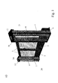
- FIG. 1a shows a perspective view of a sliding door construction which is intended to serve as an exemplary embodiment of the present invention.
- such a sliding door construction comprises fixed parts 1, which are arranged on both sides of the actual door opening.
- the door opening is closed by two sliding doors 2 and 3, wherein alternatively only one sliding door can be arranged.
- the two sliding doors 2 and 3 close synchronously and in opposite directions.
- Such sliding door structures are arranged in succession at the platform edge.
- the sliding door structures do not follow each other directly, but between sliding door constructions, as one of them is shown in Figure 1a), further wall elements are arranged, which do not constitute a door opening.
- Such wall elements are typically also formed similarly transparent. These wall elements are required inter alia, since otherwise the doors 2, 3 would encounter each other during the opening process.
- the fixed parts 1 comprise a bottom plate 6, on each of which the upper construction is attached.
- the upper construction essentially comprises in each case a frame 30, which is bounded in the head area by a cover 12.
- cover lamps 39 are arranged, which serve to emit optical signals during the opening process or respectively when closing the doors 2, 3, for example by lightning.
- As part of the superstructure of fixed parts 1 is made of aesthetic For example, a transparent area 4 arranged.
- each of these superstructures comprises a storage for the doors 2, 3, which will be described in detail below, as well as a drive.
- At least one fixed part per sliding door construction also includes a controller, which is connected, inter alia, to a total control of the entire system of sliding doors on a platform, so that a coordinated opening process or closing of all sliding doors at the right moment, that is at the correct position of the train, can be guaranteed ,
- the sliding doors 2, 3 are partially equipped with transparent areas 5.
- FIG. 1b such a sliding door construction is shown in a view from the side of the platform.
- the fixed parts 1 each comprise a frame 30.
- a transparent area 4 is arranged in each case.
- This transparent area is in a sense designed as a door, which can be opened to make the underlying functional parts such as drive and suspension and control for maintenance or installation accessible.
- these transparent areas 4 are provided with a lock 24.
- the sliding doors 2, 3 in turn likewise comprise a peripheral frame 26. Where the sliding doors adjoin one another, a sealing lip 28 is arranged on this frame. Preferably, such sealing lips 28 are configured such that the sealing lips 28 engage with one another by adjacent doors. Furthermore, transparent areas 5 are present in this frame 26. However, these transparent regions 5 do not extend all the way to the bottom, since in the lower region, due to the suspension arranged behind them, there is in each case one diaphragm region 25.
- the sliding doors can not be opened from the side of the platform in principle by simple manipulations.
- emergency opening options 23 are provided, which can only be operated using appropriate keys of the staff.
- the two sliding doors 2, 3 are designed to be cantilevered, that is, between the bottom and the lower edge of the door remains a small gap, which typically in the range of 5-30 mm.
- a fixed part 1 has, for example, a total width a of approximately 600 mm maximum, and the door opening may have a width b of 2100 mm. It is generally possible to open doors b in the range of up to 2500, normally up to 2200 mm. Depending on needs, the width of the door openings can be adjusted, and this is possible without the construction of the fixed parts 1 must be changed. So a construction is possible, which can be installed without major adjustments to the local conditions.
- the sliding doors 2, 3 have a height c, so that the upper edge of the sliding doors 2, 3 is located approximately 1500 mm above the floor. Normally, such doors are constructed with heights in the range of 1000-2000 mm.
- FIG. 1c shows a view of such a sliding door construction from the side of the tracks. It can be seen that behind the baffles 25 (see FIG. 1b) the actual suspension of the sliding doors is hidden. This suspension is covered with a cover 9, so that the pollution of the suspension can be avoided and thus the passengers can not access.
- handles 27 are provided on this side of the doors, with which the sliding doors 2, 3 can be opened.
- these handles 27 are designed to automatically open the doors when manipulated and still present, but also to allow door opening when force is applied, with no power left.
- Figure 1d shows such a sliding door construction in the open state from the side of the platform, as well as immediately below an associated floor plan. It can be seen that due to the much smaller width of the fixed structure 1, the sliding doors 2, 3 protrude laterally beyond these fixed parts 1. Specifically, each sliding door has a total width d including suspension of approximately 1700 mm (depending on the clear width of the door), since it has a guide rail 18 due to the cantilevered design, which rearwardly over the actual width of the door protrudes. Essential in this context is also that the overall construction depth is not too large, so that the required space is not too much platform surface consumed. The proposed construction is characterized by a very small construction depth, so in the above basic dimensions, the construction depth e is about 300 to 400 mm possible.
- Figure 2a shows a section through such a sliding door construction. It can be seen how two suspensions 10 and 11 are present, with both suspensions are arranged on the web side 21, and not on the platform side 20.
- the upper suspension 11 is disposed substantially in the region of the upper edge of the sliding doors 2, 3, and is described in detail below.
- the lower suspension 10 is arranged in the lowest area of the sliding doors 2, 3.
- the sliding doors 2, 3 have a cover 9, behind which the suspension 10 is hidden.
- the suspension 10 comprises a stationary part in the form of a guide element 19, which is arranged on the fixed part 1.
- a guide rail 18 is fastened to the respective sliding door and together with the guide element 19 forms a roller bearing or a ball bearing (for example a ball cage) via which the respective sliding door can be laterally displaced.
- the height f of the diaphragm area 25 or the cover 9 above the ground is approximately 400 mm, and the base plate 6 is spaced at a distance g of approximately 5 mm from the floor.
- the bottom plate 6 has a depth k of about 360 mm and is typically set back for safety reasons of the platform edge 46 by a distance 1 of about 75 mm. This value is project-specific and depends on the light profile of the train.
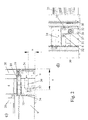
- FIGS. 2 b) -e The drive region is shown in detail in the following FIGS. 2 b) -e).
- Figure 2 b) is a sectional view. From this it can be seen that attached to the bottom plate 6 support columns 34, a horizontal guide member 19 am Fixed part is attached. This guide element 19 has a width, which in any case is less than the total width of the fixed part 1. Also attached to the bottom plate via a mounting plate 37 is the actual drive, which is ensured by a horizontally disposed electric motor 36.
- the electric motor 36 has, for example, a worm gear, which drives a toothed belt drive roller 31. Furthermore, 31 toothed belt deflection rollers 32 are arranged above this toothed belt drive roller, which should be discussed in connection with the figure 2d).
- a driver is provided with circulating toothed belt, or a fastening device 33 on the guide rail 18th
- FIGS. 2c) and d) show two views of the drive region from the tension side and the platform side, respectively. It can be seen that on the angled mounting plate 37, which is fixed by means of mounting screws 38 on the bottom plate 6, below the toothed belt drive roller 31 and above symmetrically laterally offset two Zahnriemenumlenkrollen 32 are arranged.
- the toothed belt 35 is fixed at its ends to the guide rail 18, and is deflected from each side from above via the Zahnriemenumlenkrolle 32 down to the toothed belt drive roller 31.
- the tension of the toothed belt 35 can thus be adjusted either by a lateral displacement of the toothed belt deflection rollers 32 or by a horizontal adjustment of the toothed belt drive roller 31 (also possible in each case via a sprung mounting with counter tension).
- This specific arrangement of the individual elements, ie horizontal drive motor with worm gear, toothed belt drive roller 31 with deflection over two toothed belt deflection rollers 32 allows a particularly compact design, and the use of a belt for driving proves to be particularly robust.
- the support columns are preferably designed as a hollow profile, wherein the guide member 19 is attached thereto from the platform side. It is possible to arrange two individual guide elements 19 on the two support columns 34, or else, and this is shown in FIG 2 e), it is also possible to form this guide element 19 as a rail, in which individual bearing elements are arranged distributed.
- the guide rail 18, which is fixed to the sliding doors 2, 3, is designed as a double U-profile, wherein the inner U-profile surrounds the guide member 19 for guiding and thus the inner U-profile serves as a tread, and wherein the outer U Profile is provided for the comprehensive protection of the leadership.
- the upper guide 11 is better seen in Figure 2f).
- an upper door profile 16 which forms part of the frame 26, is arranged.
- a guide rail 13 is attached.
- this guide rail has a width which corresponds approximately to the width of the sliding door 2, 3, but it can also protrude somewhat backwards over the door, as shown in Figure 1 d).
- a guide profile 15 is attached. However, it does not directly engage the guide rail 13 in the guide profile 15, but the upper guide is formed as a telescopic guide, in which a telescopic section 14 is movably arranged between these two elements.
- the telescopic profile 14 is thus both displaceable with respect to the guide rail 13 and with respect to the guide profile 15.
- the individual elements slide on each other, that is, the upper guide 11 is formed as a sliding guide.
- the use of the telescopic profile allows a particularly large width of the guide, without a chunky guide device is necessary.
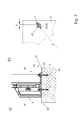
- FIG. 3a shows in detail the floor area of the construction.
- a bottom plate 6 is anchored with fastening elements 7 in the platform material 40. All elements of the fixed part 1 are then attached to this base plate 6.
- a bottom plate 6 is fixed on the platform by drilling appropriate holes in the platform. In these holes, the fasteners are either screwed (anchor bolts), or poured in, for example (anchor pins) or the like. About the above ground level upwardly protruding ends of the fasteners is now the Base plate 6 is placed, wherein the fastening elements 7 pass through corresponding provided in the bottom plate 6 holes 44, 45.
- Insulating spacer elements 42 are also provided between the bottom plate 7 and the bottom, wherein, for example, as shown in FIG. 3 a), they may be formed in the form of insulating washers 42. Similarly, 6 insulating washers 41 are now placed on top of the bottom plate and only then fixed the bottom plate with the aid of nuts 8 on the ground. The nuts 8 are screwed onto the upper end threaded fasteners 7.
- the floor panels are covered over their entire surface with an insulating coating.
- an insulating coating It is a coating of thermoplastic polyamide, such as thermoplastic PA11, which is configured with a thickness of about 0.4 mm.
- the material of the coating can be, for example, the product Rilsan® from Atofma (DE), such thermoplastic PA11 materials can be used, for example, in the fluidized bed process, in the electrostatic spray process, by powder spraying or the like. Applying, wherein the workpiece may be subjected to a surface pretreatment beforehand, for example, cleaning and application of a primer or the like.
- the holes 44, 45 designed much larger than the diameter of the fasteners 7.
- FIG. such a bottom plate is shown in FIG. It can be seen how in the area facing the platform, the fastening by three screws via three holes 45 rather in the central area, as in the lateral area, the two columns 30 of the fixed part 1 are arranged.
- the three tracks 44 facing the track area are widely distributed.
- the holes have a diameter q of 30 mm, while the anchor bolts or anchor pins 7 have a diameter r in the range of 12 mm.
- the first row of holes 44 is offset by w in the range of 110 mm to the rear, and the second row of holes 45 by 315 mm.
- the installation of such a sliding door design is particularly simple, since first the bottom plate as described above is fixed to the ground and then the fixed parts 1, that is their superstructure, put on respectively can be screwed.
- the fixed parts 1 are standard elements, which are designed independently of the width of the sliding doors. Between the fixed parts wall elements are now provided in the closed areas, which only need to be adjusted in length, which can be done either on site or before.
- the sliding doors 2, 3 can then be suspended from the track side, and last but not least the toothed belt 35 has to be placed around the corresponding elements 31 and 32, respectively, and tensioned.
- the controller can be designed so that it is self-learning, which means that when first switching on a measurement and an adjustment of the opening process takes place automatically.
- FIG. 5 shows a further exemplary embodiment of the invention.
- the upper guide is not arranged at the upper edge of the construction, but approximately at half height or slightly above the sliding doors. For aesthetic considerations, it may prove advantageous to make the top of the sliding doors as transparent as possible in order to minimize the constricting effect of such constructions occurring especially in narrow platforms.
- the upper guide is correspondingly arranged at half the height, and glass plates 48 and 49 are respectively arranged above and below.
- the arranged in the lower region lower guide is designed the same as in the above-discussed embodiment.
- the sliding doors 2, 3 are each designed with a central guide 54, but also the wall elements 47, while doing this intermediate rail 53 can hold either an upper and a lower glass plate as in the sliding doors , It is also possible to arrange this intermediate rail 53 behind a over the entire, above a lower aperture region 52 extending glass surface.
- the upper area and in particular the upper glass plate, which is exposed upwards and is not delimited by visually disturbing frame elements, enable a particularly slim construction, which is hardly distracting and restricting in the field of vision of the passengers.
- the upper guide 54 has a projection which protrudes to the rear beyond the trailing edge of the respective sliding doors. This increases the stability, especially shortly before closing the doors.
- FIG. 6 shows a section through the middle guide in detail. It can be seen that the fixed part 1 at half the height via a central support 55th has, on which the back, that is to say to the train area, a guide profile 56 is screwed.
- the guide profile 56 is formed as H-profile.
- the sliding door is formed from the upper and lower glass plates 48 and 49, respectively, and these two glass plates are held in the middle by the center support rail 54. Between the two glass plates 48 and 49 remains a horizontal slot, in which the support rail 54 has a corresponding horizontal slot, in which engages the guide profile 56 in the sense of a sliding.
- the upper guide is not designed as a telescopic guide, and it stabilizes the sliding doors only in the horizontal direction. Carrying in the vertical direction is completely taken over by the lower guide.
- this slot should for safety reasons, and to prevent contamination, have sealing lips 58, which close the slot to the people area with the door closed.
- the support rail 54 is arranged, for example, at a height H of about 1000 mm above the upper edge of the floor, and such a sliding door can have a very small thickness D of about 50 mm, and still have sufficient stability.
Landscapes
- Engineering & Computer Science (AREA)
- Mechanical Engineering (AREA)
- Platform Screen Doors And Railroad Systems (AREA)
Priority Applications (15)
| Application Number | Priority Date | Filing Date | Title |
|---|---|---|---|
| EP05106496A EP1743824A1 (fr) | 2005-07-14 | 2005-07-14 | Ensemble de porte coulissante pour perron et procédé pour son assemblage |
| TW095124148A TW200722606A (en) | 2005-07-14 | 2006-07-03 | Sliding door construction for platforms and method for assembly thereof |
| EP10163674.4A EP2213542A3 (fr) | 2005-07-14 | 2006-07-10 | Ensemble de porte coulissante pour quai et procédé pour son assemblage |
| EP06752912A EP1901951A1 (fr) | 2005-07-14 | 2006-07-10 | Construction de portes coulissantes destinee a des quais et procede d'assemblage de ladite construction |
| PCT/CH2006/000362 WO2006131018A1 (fr) | 2005-07-14 | 2006-07-10 | Construction de portes coulissantes destinee a des quais et procede d'assemblage de ladite construction |
| CN2006800252082A CN101218139B (zh) | 2005-07-14 | 2006-07-10 | 用于站台的滑动门结构及其安装方法 |
| AT08004834T ATE469804T1 (de) | 2005-07-14 | 2006-07-10 | Schiebetürkonstruktion für bahnsteige und verfahren zu deren montage |
| HK08110099.1A HK1118772B (en) | 2005-07-14 | 2006-07-10 | Sliding door construction for platforms and method for assembly thereof |
| DK08004834.1T DK1964747T3 (da) | 2005-07-14 | 2006-07-10 | Skydedørskonstruktion til perroner og fremgangsmåde til montering af disse |
| US11/995,419 US20080190031A1 (en) | 2005-07-14 | 2006-07-10 | Sliding Door Construction for Platforms and Method for Assembly Thereof |
| PL08004834T PL1964747T3 (pl) | 2005-07-14 | 2006-07-10 | Konstrukcja drzwi przesuwnych przeznaczona dla peronów oraz sposób jej montażu |
| ES08004834T ES2345465T3 (es) | 2005-07-14 | 2006-07-10 | Construccion de puertas corredizas para anden de ferrocarril y procedimiento para su montaje. |
| DE502006007132T DE502006007132D1 (de) | 2005-07-14 | 2006-07-10 | Schiebetürkonstruktion für Bahnsteige und Verfahren zu deren Montage |
| EP08004834A EP1964747B1 (fr) | 2005-07-14 | 2006-07-10 | Construction de porte coulissante pour quais et leur procédé de montage |
| HK09101171.0A HK1123591B (en) | 2005-07-14 | 2009-02-10 | Sliding door construction for platforms and method for their fitting |
Applications Claiming Priority (1)
| Application Number | Priority Date | Filing Date | Title |
|---|---|---|---|
| EP05106496A EP1743824A1 (fr) | 2005-07-14 | 2005-07-14 | Ensemble de porte coulissante pour perron et procédé pour son assemblage |
Publications (1)
| Publication Number | Publication Date |
|---|---|
| EP1743824A1 true EP1743824A1 (fr) | 2007-01-17 |
Family
ID=35355258
Family Applications (1)
| Application Number | Title | Priority Date | Filing Date |
|---|---|---|---|
| EP05106496A Withdrawn EP1743824A1 (fr) | 2005-07-14 | 2005-07-14 | Ensemble de porte coulissante pour perron et procédé pour son assemblage |
Country Status (1)
| Country | Link |
|---|---|
| EP (1) | EP1743824A1 (fr) |
Cited By (7)
| Publication number | Priority date | Publication date | Assignee | Title |
|---|---|---|---|---|
| DE102007016815A1 (de) * | 2007-04-05 | 2008-10-09 | Wolf, Gernot, Ing. | Schiebetürsystem |
| WO2008149246A1 (fr) * | 2007-06-06 | 2008-12-11 | O.C.L.A.P. S.R.L. | Porte de quai pour gares |
| WO2011048391A1 (fr) * | 2009-10-23 | 2011-04-28 | Knorr-Bremse Rail Systems (Uk) Ltd | Système de porte-écran de plateforme |
| WO2011060514A1 (fr) * | 2009-11-19 | 2011-05-26 | Bruno Francisco Rodrigues Forssell | Système de protection d'usagers sur un quai |
| EP2283198A4 (fr) * | 2008-04-02 | 2014-02-19 | Megalock Oy | Mecanisme de support et de fonctionnement de porte coulissante |
| CN110203212A (zh) * | 2019-07-11 | 2019-09-06 | 中国铁路设计集团有限公司 | 一种高铁车站站台门 |
| CN113027275A (zh) * | 2019-12-24 | 2021-06-25 | 方大智创科技有限公司 | 一种站台门传动装置 |
Citations (6)
| Publication number | Priority date | Publication date | Assignee | Title |
|---|---|---|---|---|
| GB2075564A (en) * | 1980-03-29 | 1981-11-18 | Strand Tool Co Ltd | Sliding gates |
| DE3401105A1 (de) * | 1984-01-13 | 1985-07-25 | Hörmann KG Antriebs- und Steuerungstechnik, 4834 Harsewinkel | Schiebetor-sockelbalken |
| DE4407122A1 (de) * | 1993-07-07 | 1995-03-23 | Adronit Verwaltungs Gmbh Co | Freitragendes Schiebetor |
| DE10231841A1 (de) * | 2001-07-13 | 2003-01-30 | Diefenthaler Gmbh Fa | Schiebetür |
| EP1386813A1 (fr) * | 2002-07-31 | 2004-02-04 | Hitachi, Ltd. | Dispositif de commande de portes d'un quai |
| WO2005077727A1 (fr) * | 2004-02-17 | 2005-08-25 | Mitsubishi Heavy Industries, Ltd. | Barrière amovible et procede d'ouverture/fermeture de barrière amovible |
-
2005
- 2005-07-14 EP EP05106496A patent/EP1743824A1/fr not_active Withdrawn
Patent Citations (6)
| Publication number | Priority date | Publication date | Assignee | Title |
|---|---|---|---|---|
| GB2075564A (en) * | 1980-03-29 | 1981-11-18 | Strand Tool Co Ltd | Sliding gates |
| DE3401105A1 (de) * | 1984-01-13 | 1985-07-25 | Hörmann KG Antriebs- und Steuerungstechnik, 4834 Harsewinkel | Schiebetor-sockelbalken |
| DE4407122A1 (de) * | 1993-07-07 | 1995-03-23 | Adronit Verwaltungs Gmbh Co | Freitragendes Schiebetor |
| DE10231841A1 (de) * | 2001-07-13 | 2003-01-30 | Diefenthaler Gmbh Fa | Schiebetür |
| EP1386813A1 (fr) * | 2002-07-31 | 2004-02-04 | Hitachi, Ltd. | Dispositif de commande de portes d'un quai |
| WO2005077727A1 (fr) * | 2004-02-17 | 2005-08-25 | Mitsubishi Heavy Industries, Ltd. | Barrière amovible et procede d'ouverture/fermeture de barrière amovible |
Cited By (9)
| Publication number | Priority date | Publication date | Assignee | Title |
|---|---|---|---|---|
| DE102007016815A1 (de) * | 2007-04-05 | 2008-10-09 | Wolf, Gernot, Ing. | Schiebetürsystem |
| WO2008122348A1 (fr) | 2007-04-05 | 2008-10-16 | Gernot Wolf | Système de porte coulissante |
| WO2008149246A1 (fr) * | 2007-06-06 | 2008-12-11 | O.C.L.A.P. S.R.L. | Porte de quai pour gares |
| US8387541B2 (en) | 2007-06-06 | 2013-03-05 | O.C.L.A.P. S.R.L. | Platform gate for train stations |
| EP2283198A4 (fr) * | 2008-04-02 | 2014-02-19 | Megalock Oy | Mecanisme de support et de fonctionnement de porte coulissante |
| WO2011048391A1 (fr) * | 2009-10-23 | 2011-04-28 | Knorr-Bremse Rail Systems (Uk) Ltd | Système de porte-écran de plateforme |
| WO2011060514A1 (fr) * | 2009-11-19 | 2011-05-26 | Bruno Francisco Rodrigues Forssell | Système de protection d'usagers sur un quai |
| CN110203212A (zh) * | 2019-07-11 | 2019-09-06 | 中国铁路设计集团有限公司 | 一种高铁车站站台门 |
| CN113027275A (zh) * | 2019-12-24 | 2021-06-25 | 方大智创科技有限公司 | 一种站台门传动装置 |
Similar Documents
| Publication | Publication Date | Title |
|---|---|---|
| EP1964747B1 (fr) | Construction de porte coulissante pour quais et leur procédé de montage | |
| EP0230999B1 (fr) | Porte roulante verticale pour basses hauteurs de linteau | |
| DE69518742T2 (de) | Overhead door and track therefor | |
| EP0883726A1 (fr) | Systeme de porte coulissante | |
| EP2685039A2 (fr) | Dispositif de guidage, chariot et rail de guidage | |
| DE8706868U1 (de) | Antriebsvorrichtung für Schranke od. dgl. | |
| EP3225771B1 (fr) | Seuil de porte pour une porte coulissante et porte coulissante | |
| DE68907768T2 (de) | Faltwand, bestehend aus miteinander gelenkig verbundenen doppelwandigen Flügeln. | |
| EP1743824A1 (fr) | Ensemble de porte coulissante pour perron et procédé pour son assemblage | |
| DE102014119145A1 (de) | Schiebetor und Baukastensystem für ein Schiebetor | |
| EP1836358B1 (fr) | Element de façade prefabrique | |
| DE3001993A1 (de) | Rollenanordnung zur befestigung an einer tuer o.dgl. | |
| WO1999022104A1 (fr) | Systeme modulaire de construction de mecanismes d'entrainement de portes ou de fenetres | |
| DE10157805A1 (de) | Verschiebbares und verschwenkbares Türflügelelement | |
| EP2708693B1 (fr) | Cadre de battant ouvrant-coulissant | |
| EP2058456A1 (fr) | Toit | |
| DE102021121213A1 (de) | Schiebetor mit einem Schiebetorkörper sowie Verfahren zum Montieren eines Schiebetors | |
| DE102016111410A1 (de) | Mittelstütze für eine Gebäudeöffnung mit großer lichter Breite | |
| EP3984941B1 (fr) | Ascenseur, en particulier permettant de transporter des personnes | |
| DE10353791B4 (de) | Horizontales Seitenlauftor mit Unterflur-Führungs- und Antriebskanal | |
| DE3037678A1 (de) | Segmenttor | |
| DE202024101220U1 (de) | Antriebsvorrichtung mit einer Führungsschiene für einen verschiebbaren Flügel als Schiebeflügel oder verschiebbaren Hebe-Schiebeflügel eines Fensters oder einer Tür | |
| DE102016101377A1 (de) | Schiebetor und Modulsystem zum Herstellen eines Schiebetors | |
| DE7918647U1 (de) | Schiebetuer | |
| DE10347283B4 (de) | Vorrichtung für insbesondere motorisch betätigte Türen eines Schacht- oder Aufzugskabinenzugangs |
Legal Events
| Date | Code | Title | Description |
|---|---|---|---|
| PUAI | Public reference made under article 153(3) epc to a published international application that has entered the european phase |
Free format text: ORIGINAL CODE: 0009012 |
|
| AK | Designated contracting states |
Kind code of ref document: A1 Designated state(s): AT BE BG CH CY CZ DE DK EE ES FI FR GB GR HU IE IS IT LI LT LU LV MC NL PL PT RO SE SI SK TR |
|
| AX | Request for extension of the european patent |
Extension state: AL BA HR MK YU |
|
| RIN1 | Information on inventor provided before grant (corrected) |
Inventor name: EGLI, PETER Inventor name: WINKELMANN, UELI Inventor name: HUG, ROBERT |
|
| AKX | Designation fees paid | ||
| REG | Reference to a national code |
Ref country code: DE Ref legal event code: 8566 |
|
| STAA | Information on the status of an ep patent application or granted ep patent |
Free format text: STATUS: THE APPLICATION IS DEEMED TO BE WITHDRAWN |
|
| 18D | Application deemed to be withdrawn |
Effective date: 20070718 |