EP1744355A2 - Magasin pour plaquettes de semiconducteurs ou d'objets similaires - Google Patents
Magasin pour plaquettes de semiconducteurs ou d'objets similaires Download PDFInfo
- Publication number
- EP1744355A2 EP1744355A2 EP06076347A EP06076347A EP1744355A2 EP 1744355 A2 EP1744355 A2 EP 1744355A2 EP 06076347 A EP06076347 A EP 06076347A EP 06076347 A EP06076347 A EP 06076347A EP 1744355 A2 EP1744355 A2 EP 1744355A2
- Authority
- EP
- European Patent Office
- Prior art keywords
- guide
- base plate
- along
- wafer
- base
- Prior art date
- Legal status (The legal status is an assumption and is not a legal conclusion. Google has not performed a legal analysis and makes no representation as to the accuracy of the status listed.)
- Granted
Links
Images


Classifications
-
- H—ELECTRICITY
- H10—SEMICONDUCTOR DEVICES; ELECTRIC SOLID-STATE DEVICES NOT OTHERWISE PROVIDED FOR
- H10P—GENERIC PROCESSES OR APPARATUS FOR THE MANUFACTURE OR TREATMENT OF DEVICES COVERED BY CLASS H10
- H10P72/00—Handling or holding of wafers, substrates or devices during manufacture or treatment thereof
- H10P72/10—Handling or holding of wafers, substrates or devices during manufacture or treatment thereof using carriers specially adapted therefor, e.g. front opening unified pods [FOUP]
- H10P72/12—Vertical boat type carrier whereby the substrates are horizontally supported, e.g. comprising rod-shaped elements
-
- B—PERFORMING OPERATIONS; TRANSPORTING
- B65—CONVEYING; PACKING; STORING; HANDLING THIN OR FILAMENTARY MATERIAL
- B65G—TRANSPORT OR STORAGE DEVICES, e.g. CONVEYORS FOR LOADING OR TIPPING, SHOP CONVEYOR SYSTEMS OR PNEUMATIC TUBE CONVEYORS
- B65G49/00—Conveying systems characterised by their application for specified purposes not otherwise provided for
- B65G49/05—Conveying systems characterised by their application for specified purposes not otherwise provided for for fragile or damageable materials or articles
- B65G49/06—Conveying systems characterised by their application for specified purposes not otherwise provided for for fragile or damageable materials or articles for fragile sheets, e.g. glass
- B65G49/068—Stacking or destacking devices; Means for preventing damage to stacked sheets, e.g. spaces
-
- H—ELECTRICITY
- H10—SEMICONDUCTOR DEVICES; ELECTRIC SOLID-STATE DEVICES NOT OTHERWISE PROVIDED FOR
- H10P—GENERIC PROCESSES OR APPARATUS FOR THE MANUFACTURE OR TREATMENT OF DEVICES COVERED BY CLASS H10
- H10P72/00—Handling or holding of wafers, substrates or devices during manufacture or treatment thereof
-
- H—ELECTRICITY
- H10—SEMICONDUCTOR DEVICES; ELECTRIC SOLID-STATE DEVICES NOT OTHERWISE PROVIDED FOR
- H10P—GENERIC PROCESSES OR APPARATUS FOR THE MANUFACTURE OR TREATMENT OF DEVICES COVERED BY CLASS H10
- H10P72/00—Handling or holding of wafers, substrates or devices during manufacture or treatment thereof
- H10P72/10—Handling or holding of wafers, substrates or devices during manufacture or treatment thereof using carriers specially adapted therefor, e.g. front opening unified pods [FOUP]
- H10P72/17—Handling or holding of wafers, substrates or devices during manufacture or treatment thereof using carriers specially adapted therefor, e.g. front opening unified pods [FOUP] specially adapted for supporting large square shaped substrates
Definitions
- the invention relates to a wafer magazine for semiconductor wafers or wafer-like articles having the features according to the preamble of claims 1 and 2.
- wafer magazine and wafers will be discussed below.
- wafer-like articles such as thin film solar cells in the form of semiconductor thin films on glass substrates.
- a large number of wafer magazines are known from the prior art, which are used in particular for the intermediate storage of semiconductor wafers in various processing stages in automated systems of semiconductor technology.
- a compact embodiment of such a wafer magazine comprises a base plate, which rests on a base body, without being attached thereto.
- Base plate and basic body lie together on a base.
- On the main body a plurality of limiting structures are fixed, which extend transversely, in particular perpendicularly, to the base surface. These boundary structures are around the base plate arranged around and form an upwardly open cage-like structure.
- the delimiting structures are provided, for example, in the form of elongated spars of the same length.
- the base plate On the basis defined by the base body and the peripheral boundary structures bottom of this cage-like structure, the base plate is loose.
- the base plate can be moved up and down along the base along a direction of travel oriented substantially perpendicular to the base area between the upper edge of the delimiting structures and the bearing surface of the base plate.
- a drive unit for example, a means of a spindle of a stepping motor driven piston is provided, which passes through the base body from below and presses the base plate of the main body upwards.
- a gripping arm can pivot a wafer fixed to the gripping arm over the base plate. There, the wafer comes to rest at a defined distance of a few millimeters parallel to the base plate. Then, the fixation of the wafer to the gripping arm dissolves, so that the wafer falls after a fall distance of the distance to the base plate on the surface of the base plate.
- the base plate is lowered slightly downwards by means of the drive unit, and the loading process can start anew. The next wafer falls directly onto the surface of the previous one. Controlled by sensors, the base plate is positioned so that the top edge of the wafer stack is always at a certain level. This process can be repeated until the base plate comes to rest on the base body and the magazine can no longer receive more wafers.
- a larger number of wafers can be stored in a small space and transported as a arranged in the wafer magazine production unit, for example, from a first to a downstream facility, where the wafers go through the next process step.
- shell breaks occur at the edges of the wafers.
- the material of semiconductor wafers but also of glass flakes is often very brittle, so that their edges sensitive to point loads react. Under mechanical stress, the material splits quickly, forming the characteristic terasse-like structures of the mussel fractures.
- the present invention is therefore based on the object to provide a wafer magazine, which overcomes the above-mentioned disadvantages and at the same time is simple and inexpensive.
- the two described solutions to the problem are based on the common principle of avoiding or at least reducing the critical frictional forces between the edges of the wafer stack and the delimiting structures.
- a plurality of the delimiting structures comprise an inner side facing the base plate and a guide device with a guide means extending at least on the inner side of the delimiting structures. wherein the guide means is formed transversely to the direction of travel flexible.
- the guide means are designed to be flexible transversely to the direction of travel, the mechanical stress on the edges are reduced.
- the material of the guide means is selected such that the static and sliding friction of the wafer edges on the guide means is low. The still occurring low frictional forces between the wafer edges and the guide means are at least partially taken up by a deflection movement of the guide means which is made possible by the flexibility of the guide means and oriented transversely to the direction of travel.
- a guide means is to be considered if it escapes in a caused by the movement of the base plate mechanical interaction with a wafer edge by a relative movement to the wafer edge such that the wafer edge is loaded with lower forces than if no relative movement of the Guiding agent occur.
- the Reduction of the acting forces is so great that significantly less shell fractures occur at the wafer edges.
- the second solution following the same basic principle provides that the guide means and the base plate cooperate in such a way that the movement of the base plate along the direction of travel causes a movement of the guide means which is oriented substantially along the direction of travel and substantially the same.
- the guide means are mechanically fixed to the base plate. This guarantees simultaneous movement.
- the guide device is designed accordingly so that the required movement of the guide means is ensured.
- the base plate so difficult, ie, for example, in accordance with solid metal construction form, that their weight is greater than the sum of all movement of the base plate along the travel direction on the guide means acting on the base plate movement-inhibiting forces.
- This has the advantage that the drive unit must exert no force on the base plate in the form of a stamp from a stepping motor from below against the base plate pressing punch when lowering the base plate. Gravity alone is enough to lower the base plate back to the base body. If the punch of the drive unit is lower than the lowest position of the base plate, the drive unit is automatically decoupled from the base plate. The power coupling between the drive unit and the base plate takes place in the opposite direction solely by traction.
- the guide means in the form of adjacent to the inside of the boundary structure arranged guide bands.
- Such belts or suitable belts made of various plastics are available as very inexpensive mass-produced on the market.
- the guide band is preferably positioned by an upper positioning means and a lower positioning means relative to the inside of the limiting structure.
- the upper positioning means is formed as an upper deflection roller for deflecting the guide band by substantially 180 °.
- This deflection roller changes the extension direction of the guide band from the inside of the delimiting structure to an outer side of the delimiting structure facing away from the base plate.
- Another embodiment of the wafer magazine provides a clamping device arranged between the upper deflection roller and the main body. This preferably mechanically acting tensioning device biases the guide belt along its extension direction.
- the lower positioning means is provided as a fixation of the guide band either on the boundary structure or on the base plate.
- the tensioning device is designed in such a way that, during the raising of the base plate, it winds the guide band moving over the upper deflection roller by means of a spring-loaded winding mechanism.
- An alternative embodiment of the wafer magazine provides for forming the lower positioning means as a lower deflection roller for deflecting the guide belt by substantially 180 °.
- the guide band can be formed as a circumferential, one-piece belt, which runs closed in itself from the inside of the delimiting structure to the outside of the delimiting structure.
- This application form can be realized in both basic variants of the invention.
- the flexibility of the guide means is given transversely to the direction of travel by its spacing to the inside of the boundary structure.
- Positioning means configured as deflection rollers are preferably rotatably mounted about an axis of rotation in such a way that the guide belt can be moved along its extension direction while rotating the lower and / or upper deflection roller.
- the deflection rollers are designed ball bearings.
- the pulleys as gears and the guide band are at least partially formed as a cooperating with the gears timing belt.
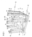
- FIG. 1 shows the perspective view of a preferred embodiment of the wafer magazine.
- a base plate 2 On a frame-shaped main body 1, which covers a substantially square base, a base plate 2 is arranged. On the four sides of the main body 1 two boundary structures in the form of limiting beams 10 are arranged symmetrically opposite each. These limiting spars 10 extend perpendicular to the base surface and are all formed identical to one another. Together with the main body 1 and the base plate 2 lying thereon, they form the overall structure of an upwardly open cage.
- Wafers can be stacked on top of the base plate 2 up to the upper edge of the limiting spars 10. The loading and unloading of the wafers takes place as shown in the introduction to the description.
- the base body 1 comprises a mechanical mounting structure in the form of a groove 14 running along one or more sides.
- the wafer magazine can be inserted into a system provided on the system , Insert correspondingly formed mechanical guide mechanism.
- Each boundary spar 10 is constructed from a cuboid, elongated body. Toward the base plate 2, the limiting spars 10 each have an inner side 11, facing away from the base plate 2, an outer side 12.
- Each limiting beam comprises a guide device 100.
- This guide device 100 has, in particular, a guide means in the form of a guide strip 101.
- This guide band 101 is formed as a closed toothed belt, which is spaced from the inside 11 and the outside 12 along the Extending direction of the limiting spar 10 extends from the lower end to the upper end.
- Positioning means in the form of deflection rollers 102, 103 are respectively provided at the two ends, which deflect the self-contained toothed belt 101 from the inner side 11 to the outer side 12 of the limiting beam 10.
- the toothed belt 101 is provided in the form of a flat band which has teeth exclusively on the side directed toward the limiting spar 10 side.
- the toothed belt 101 has a smooth surface.
- the upper and lower pulley 102, 103 are formed as cooperating with the teeth of the toothed belt 101 gears, which are rotatably mounted respectively about axes of rotation D.
- These gearwheels have guide cheeks 105 on their edge regions arranged on the outside in relation to the axis of rotation D, which prevent the toothed belt 101 from slipping along the axes of rotation D.
- the base plate 2 comprises no fixing means for attachment to the base body 1.
- the base plate 2 is loosely on the base body 1, so that they can move along with the stacked on the base plate 2 wafers along a direction perpendicular to the base oriented travel direction V relative to the limiting spars 10 ,
- the base plate 2 extends at least in the region of the inner sides 11 of the limiting spars 10 up to the guide belts 101 zoom.
- the adjacent region between the limiting beams 10 and the base plate 2 is shown along the perspective shown in the figure 1 with the arrows II - II in Figures 2a and 2c for the two basic solution variants.
- FIG. 2 a shows the variant that the guide strip 101 does not interact with the base plate 2.
- the guide belt 101 is arranged on the inside 11 of the limiting beam 10 by the correspondingly wide formation of the upper and lower gears 102, 103 spaced from the inside 11.
- a flexibility of the guide belt 101 is given transversely to the direction of travel V.
- the upper and lower gear 102, 103 are each mounted with ball bearings 106 about the axes of rotation D.
- particularly low movement-inhibiting forces of the self-contained toothed belt 101 are ensured. This may also be advantageous in this first variant of the solution because the toothed belt 101 is moved along with correspondingly strong frictional forces between it and the wafer edges.
- FIGS. 2b and 2d each show modifications of the first and second variants of the solution shown in FIGS. 2a and 2c. Both modifications have in common that the guide means 101 are not formed as a self-contained belt. Rather, the guide means 101 is provided in the form of a substantially arranged only along the inner side 11 of the limiting spar guide band.
- only one upper and one lower positioning means 102, 103 are provided on the inner side 11 for the spaced arrangement of the guide means 101. This is due to the immovable upper and lower positioning means is the simplest embodiment constructed.
- the guide strip 101 is coupled to the base plate 2 in the region of the base plate 2 by means of a fastening means 107. Thereby, the movement of the base plate 2 is transmitted to the guide belt 101.
- a clamping device 104 is provided on the outer side 12 of the limiting spar 10. This tensioning device 104 ensures that the guide means 101 moved by the movement of the base plate 2 is always under the same mechanical pretensioning. For this purpose, it is necessary to provide the tensioning device 104 with a winding mechanism that up or unwinds the guide means 101 supplied during the up and down movement of the base plate 2.
- the basic square shape of the basic body 1 and the base plate 2 shown are by no means compulsory. Likewise, a rectangular or round structure oriented on the shape of the wafers is possible.
- the number of limiting structures 10 is largely variable. For a square basic shape are Usually at least one limiting structure 10 is necessary on each side in order to ensure an all-round guidance and securing of the wafer stack. With a round structure, at least three appropriately distributed limiting structures would be necessary for this.
Landscapes
- Container, Conveyance, Adherence, Positioning, Of Wafer (AREA)
- Sheets, Magazines, And Separation Thereof (AREA)
- Packaging For Recording Disks (AREA)
- Packaging Frangible Articles (AREA)
Applications Claiming Priority (1)
| Application Number | Priority Date | Filing Date | Title |
|---|---|---|---|
| DE102005033859A DE102005033859B3 (de) | 2005-07-12 | 2005-07-12 | Wafermagazin für Halbleiterwafer oder waferartige Gegenstände |
Publications (3)
| Publication Number | Publication Date |
|---|---|
| EP1744355A2 true EP1744355A2 (fr) | 2007-01-17 |
| EP1744355A3 EP1744355A3 (fr) | 2008-08-06 |
| EP1744355B1 EP1744355B1 (fr) | 2019-08-07 |
Family
ID=37401026
Family Applications (1)
| Application Number | Title | Priority Date | Filing Date |
|---|---|---|---|
| EP06076347.1A Active EP1744355B1 (fr) | 2005-07-12 | 2006-06-28 | Magasin pour plaquettes de semiconducteurs ou d'objets similaires |
Country Status (3)
| Country | Link |
|---|---|
| EP (1) | EP1744355B1 (fr) |
| DE (1) | DE102005033859B3 (fr) |
| NO (1) | NO20063222L (fr) |
Cited By (1)
| Publication number | Priority date | Publication date | Assignee | Title |
|---|---|---|---|---|
| CN116198822A (zh) * | 2022-12-27 | 2023-06-02 | 沈阳农业大学 | 一种生物实验室用培养皿批量放置转移装置 |
Families Citing this family (5)
| Publication number | Priority date | Publication date | Assignee | Title |
|---|---|---|---|---|
| DE102008030629A1 (de) | 2008-06-20 | 2009-12-24 | Aci-Ecotec Gmbh & Co. Kg | Wafermagazin |
| DE202009014371U1 (de) | 2009-10-23 | 2011-02-24 | Aleo Solar Ag | Bauelemente-Magazin und Solarzellen-Positioniervorrichtung |
| DE102010005202B4 (de) | 2010-01-21 | 2020-04-09 | Q-Cells Se | Magazin für einen photovoltaischen Wafer- und/oder Zellstapel mit einem Magazineinsatz zur Aufnahme desselben |
| DE102011013511B4 (de) | 2011-03-10 | 2017-01-12 | Fraunhofer-Gesellschaft zur Förderung der angewandten Forschung e.V. | Plattenmagazin und Vorrichtung zum Abseparieren von plattenförmigen Gegenständen |
| CN114249086B (zh) * | 2020-09-24 | 2024-11-01 | 深南电路股份有限公司 | 一种上板设备 |
Citations (1)
| Publication number | Priority date | Publication date | Assignee | Title |
|---|---|---|---|---|
| JPH05116832A (ja) | 1991-10-25 | 1993-05-14 | Hitachi Electron Eng Co Ltd | フレキシブルデイスクスタツク機構 |
Family Cites Families (7)
| Publication number | Priority date | Publication date | Assignee | Title |
|---|---|---|---|---|
| US3915317A (en) * | 1974-09-17 | 1975-10-28 | Eastman Kodak Co | Apparatus for collecting articles in separate stacks |
| JPH03106721A (ja) * | 1989-09-21 | 1991-05-07 | Mitsubishi Electric Corp | 縦型ウエーハ搬送装置 |
| JP3163884B2 (ja) * | 1994-02-18 | 2001-05-08 | 株式会社ダイフク | 荷保管設備 |
| US5950643A (en) * | 1995-09-06 | 1999-09-14 | Miyazaki; Takeshiro | Wafer processing system |
| US6427096B1 (en) * | 1999-02-12 | 2002-07-30 | Honeywell International Inc. | Processing tool interface apparatus for use in manufacturing environment |
| KR100672634B1 (ko) * | 2001-12-19 | 2007-02-09 | 엘지.필립스 엘시디 주식회사 | 액정표시소자의 기판 반송 장치 및 방법 |
| US6886696B2 (en) * | 2003-01-15 | 2005-05-03 | Taiwan Semiconductor Manufacturing Co., Ltd | Wafer container with removable sidewalls |
-
2005
- 2005-07-12 DE DE102005033859A patent/DE102005033859B3/de not_active Expired - Lifetime
-
2006
- 2006-06-28 EP EP06076347.1A patent/EP1744355B1/fr active Active
- 2006-07-11 NO NO20063222A patent/NO20063222L/no not_active Application Discontinuation
Patent Citations (1)
| Publication number | Priority date | Publication date | Assignee | Title |
|---|---|---|---|---|
| JPH05116832A (ja) | 1991-10-25 | 1993-05-14 | Hitachi Electron Eng Co Ltd | フレキシブルデイスクスタツク機構 |
Cited By (1)
| Publication number | Priority date | Publication date | Assignee | Title |
|---|---|---|---|---|
| CN116198822A (zh) * | 2022-12-27 | 2023-06-02 | 沈阳农业大学 | 一种生物实验室用培养皿批量放置转移装置 |
Also Published As
| Publication number | Publication date |
|---|---|
| DE102005033859B3 (de) | 2006-12-14 |
| EP1744355B1 (fr) | 2019-08-07 |
| NO20063222L (no) | 2007-01-15 |
| EP1744355A3 (fr) | 2008-08-06 |
Similar Documents
| Publication | Publication Date | Title |
|---|---|---|
| DE102008006171B3 (de) | Vorrichtung zur Behandlung von Werkstücken, insbesondere von Fahrzeugrädern, insbesondere im Rahmen einer Pulverlackierung | |
| EP0564901A2 (fr) | Dispositif d'avance pour tôle | |
| EP0311699A1 (fr) | Dispositif de transport pour retourner au même niveau des colis de détail | |
| EP1744355B1 (fr) | Magasin pour plaquettes de semiconducteurs ou d'objets similaires | |
| DE102013016707A1 (de) | Transportvorrichtung und Bestückvorrichtung damit | |
| DE60301201T2 (de) | Vorrichtung zum Bewegen von Produkten | |
| EP0321680B1 (fr) | Dispositif servant à enlever des articles | |
| EP3543182A2 (fr) | Dispositif de transport, de rotation et de déplacement des marchandises | |
| DE3523901A1 (de) | Glasplattenschleifmaschine | |
| DE10125854A1 (de) | Transporteinrichtung, insbesondere Transportband | |
| DE29713290U1 (de) | Rollenbandförderanlage | |
| DE3403550A1 (de) | Transport- und lagergestell | |
| DE202024104580U1 (de) | Versiegel- und Förderfolienverpackungsmaschine | |
| DE69406263T2 (de) | Träger für ein Lineartriebwerk mit Selbstantrieb | |
| DE3877128T2 (de) | Vorrichtung zum verschieben von spulentransporttraegern, die aus einer scheibenartigen grundplatte und einem mittigen zapfen bestehen, in einer spinnerei. | |
| WO2011050868A1 (fr) | Système de stockage à moyens d'entraînement pouvant être tendus individuellement | |
| DE29519805U1 (de) | Transfereinrichtung für Fördergut | |
| DE3613580C2 (fr) | ||
| DE102022112578B4 (de) | Kurvenfördermodul für eine Transporteinrichtung zum Transportieren von Stückgütern, insbesondere von Paketen, entlang eines Transportweges | |
| DE102008030629A1 (de) | Wafermagazin | |
| DE20310185U1 (de) | Rollenbahn | |
| DE102019117026B4 (de) | Transportsystem | |
| DE3808042C2 (fr) | ||
| DE458466C (de) | Verzinnungsmaschine fuer Bleche | |
| DE102023131012A1 (de) | Kanalfahrzeug und Regalbediensystem mit einem solchen |
Legal Events
| Date | Code | Title | Description |
|---|---|---|---|
| PUAI | Public reference made under article 153(3) epc to a published international application that has entered the european phase |
Free format text: ORIGINAL CODE: 0009012 |
|
| AK | Designated contracting states |
Kind code of ref document: A2 Designated state(s): AT BE BG CH CY CZ DE DK EE ES FI FR GB GR HU IE IS IT LI LT LU LV MC NL PL PT RO SE SI SK TR |
|
| AX | Request for extension of the european patent |
Extension state: AL BA HR MK YU |
|
| PUAL | Search report despatched |
Free format text: ORIGINAL CODE: 0009013 |
|
| AK | Designated contracting states |
Kind code of ref document: A3 Designated state(s): AT BE BG CH CY CZ DE DK EE ES FI FR GB GR HU IE IS IT LI LT LU LV MC NL PL PT RO SE SI SK TR |
|
| AX | Request for extension of the european patent |
Extension state: AL BA HR MK RS |
|
| RIC1 | Information provided on ipc code assigned before grant |
Ipc: H01L 21/00 20060101ALI20080630BHEP Ipc: H01L 31/18 20060101ALI20080630BHEP Ipc: B65G 49/06 20060101AFI20080630BHEP Ipc: H01L 21/677 20060101ALI20080630BHEP Ipc: H01L 21/673 20060101ALI20080630BHEP |
|
| 17P | Request for examination filed |
Effective date: 20090130 |
|
| 17Q | First examination report despatched |
Effective date: 20090317 |
|
| AKX | Designation fees paid |
Designated state(s): AT BE BG CH CY CZ DE DK EE ES FI FR GB GR HU IE IS IT LI LT LU LV MC NL PL PT RO SE SI SK TR |
|
| RAP1 | Party data changed (applicant data changed or rights of an application transferred) |
Owner name: Q-CELLS SE |
|
| 19U | Interruption of proceedings before grant |
Effective date: 20120701 |
|
| 19W | Proceedings resumed before grant after interruption of proceedings |
Effective date: 20140303 |
|
| REG | Reference to a national code |
Ref country code: DE Ref legal event code: R079 Ref document number: 502006016320 Country of ref document: DE Free format text: PREVIOUS MAIN CLASS: H01L0021673000 Ipc: B65G0049060000 |
|
| GRAP | Despatch of communication of intention to grant a patent |
Free format text: ORIGINAL CODE: EPIDOSNIGR1 |
|
| STAA | Information on the status of an ep patent application or granted ep patent |
Free format text: STATUS: GRANT OF PATENT IS INTENDED |
|
| RIC1 | Information provided on ipc code assigned before grant |
Ipc: H01L 21/67 20060101ALI20180228BHEP Ipc: H01L 21/673 20060101ALI20180228BHEP Ipc: B65G 49/06 20060101AFI20180228BHEP |
|
| INTG | Intention to grant announced |
Effective date: 20180320 |
|
| RAP1 | Party data changed (applicant data changed or rights of an application transferred) |
Owner name: HANWHA Q CELLS GMBH |
|
| GRAS | Grant fee paid |
Free format text: ORIGINAL CODE: EPIDOSNIGR3 |
|
| GRAA | (expected) grant |
Free format text: ORIGINAL CODE: 0009210 |
|
| STAA | Information on the status of an ep patent application or granted ep patent |
Free format text: STATUS: THE PATENT HAS BEEN GRANTED |
|
| AK | Designated contracting states |
Kind code of ref document: B1 Designated state(s): AT BE BG CH CY CZ DE DK EE ES FI FR GB GR HU IE IS IT LI LT LU LV MC NL PL PT RO SE SI SK TR |
|
| REG | Reference to a national code |
Ref country code: GB Ref legal event code: FG4D Free format text: NOT ENGLISH |
|
| REG | Reference to a national code |
Ref country code: CH Ref legal event code: EP Ref country code: AT Ref legal event code: REF Ref document number: 1163520 Country of ref document: AT Kind code of ref document: T Effective date: 20190815 |
|
| REG | Reference to a national code |
Ref country code: DE Ref legal event code: R096 Ref document number: 502006016320 Country of ref document: DE |
|
| REG | Reference to a national code |
Ref country code: IE Ref legal event code: FG4D Free format text: LANGUAGE OF EP DOCUMENT: GERMAN |
|
| REG | Reference to a national code |
Ref country code: NL Ref legal event code: FP |
|
| REG | Reference to a national code |
Ref country code: LT Ref legal event code: MG4D |
|
| PG25 | Lapsed in a contracting state [announced via postgrant information from national office to epo] |
Ref country code: SE Free format text: LAPSE BECAUSE OF FAILURE TO SUBMIT A TRANSLATION OF THE DESCRIPTION OR TO PAY THE FEE WITHIN THE PRESCRIBED TIME-LIMIT Effective date: 20190807 Ref country code: BG Free format text: LAPSE BECAUSE OF FAILURE TO SUBMIT A TRANSLATION OF THE DESCRIPTION OR TO PAY THE FEE WITHIN THE PRESCRIBED TIME-LIMIT Effective date: 20191107 Ref country code: LT Free format text: LAPSE BECAUSE OF FAILURE TO SUBMIT A TRANSLATION OF THE DESCRIPTION OR TO PAY THE FEE WITHIN THE PRESCRIBED TIME-LIMIT Effective date: 20190807 Ref country code: FI Free format text: LAPSE BECAUSE OF FAILURE TO SUBMIT A TRANSLATION OF THE DESCRIPTION OR TO PAY THE FEE WITHIN THE PRESCRIBED TIME-LIMIT Effective date: 20190807 Ref country code: PT Free format text: LAPSE BECAUSE OF FAILURE TO SUBMIT A TRANSLATION OF THE DESCRIPTION OR TO PAY THE FEE WITHIN THE PRESCRIBED TIME-LIMIT Effective date: 20191209 |
|
| PG25 | Lapsed in a contracting state [announced via postgrant information from national office to epo] |
Ref country code: LV Free format text: LAPSE BECAUSE OF FAILURE TO SUBMIT A TRANSLATION OF THE DESCRIPTION OR TO PAY THE FEE WITHIN THE PRESCRIBED TIME-LIMIT Effective date: 20190807 Ref country code: IS Free format text: LAPSE BECAUSE OF FAILURE TO SUBMIT A TRANSLATION OF THE DESCRIPTION OR TO PAY THE FEE WITHIN THE PRESCRIBED TIME-LIMIT Effective date: 20191207 Ref country code: GR Free format text: LAPSE BECAUSE OF FAILURE TO SUBMIT A TRANSLATION OF THE DESCRIPTION OR TO PAY THE FEE WITHIN THE PRESCRIBED TIME-LIMIT Effective date: 20191108 Ref country code: ES Free format text: LAPSE BECAUSE OF FAILURE TO SUBMIT A TRANSLATION OF THE DESCRIPTION OR TO PAY THE FEE WITHIN THE PRESCRIBED TIME-LIMIT Effective date: 20190807 |
|
| PG25 | Lapsed in a contracting state [announced via postgrant information from national office to epo] |
Ref country code: TR Free format text: LAPSE BECAUSE OF FAILURE TO SUBMIT A TRANSLATION OF THE DESCRIPTION OR TO PAY THE FEE WITHIN THE PRESCRIBED TIME-LIMIT Effective date: 20190807 |
|
| PG25 | Lapsed in a contracting state [announced via postgrant information from national office to epo] |
Ref country code: DK Free format text: LAPSE BECAUSE OF FAILURE TO SUBMIT A TRANSLATION OF THE DESCRIPTION OR TO PAY THE FEE WITHIN THE PRESCRIBED TIME-LIMIT Effective date: 20190807 Ref country code: PL Free format text: LAPSE BECAUSE OF FAILURE TO SUBMIT A TRANSLATION OF THE DESCRIPTION OR TO PAY THE FEE WITHIN THE PRESCRIBED TIME-LIMIT Effective date: 20190807 Ref country code: IT Free format text: LAPSE BECAUSE OF FAILURE TO SUBMIT A TRANSLATION OF THE DESCRIPTION OR TO PAY THE FEE WITHIN THE PRESCRIBED TIME-LIMIT Effective date: 20190807 Ref country code: EE Free format text: LAPSE BECAUSE OF FAILURE TO SUBMIT A TRANSLATION OF THE DESCRIPTION OR TO PAY THE FEE WITHIN THE PRESCRIBED TIME-LIMIT Effective date: 20190807 Ref country code: RO Free format text: LAPSE BECAUSE OF FAILURE TO SUBMIT A TRANSLATION OF THE DESCRIPTION OR TO PAY THE FEE WITHIN THE PRESCRIBED TIME-LIMIT Effective date: 20190807 |
|
| PG25 | Lapsed in a contracting state [announced via postgrant information from national office to epo] |
Ref country code: IS Free format text: LAPSE BECAUSE OF FAILURE TO SUBMIT A TRANSLATION OF THE DESCRIPTION OR TO PAY THE FEE WITHIN THE PRESCRIBED TIME-LIMIT Effective date: 20200224 Ref country code: CZ Free format text: LAPSE BECAUSE OF FAILURE TO SUBMIT A TRANSLATION OF THE DESCRIPTION OR TO PAY THE FEE WITHIN THE PRESCRIBED TIME-LIMIT Effective date: 20190807 Ref country code: SK Free format text: LAPSE BECAUSE OF FAILURE TO SUBMIT A TRANSLATION OF THE DESCRIPTION OR TO PAY THE FEE WITHIN THE PRESCRIBED TIME-LIMIT Effective date: 20190807 |
|
| REG | Reference to a national code |
Ref country code: DE Ref legal event code: R097 Ref document number: 502006016320 Country of ref document: DE |
|
| PLBE | No opposition filed within time limit |
Free format text: ORIGINAL CODE: 0009261 |
|
| STAA | Information on the status of an ep patent application or granted ep patent |
Free format text: STATUS: NO OPPOSITION FILED WITHIN TIME LIMIT |
|
| PG2D | Information on lapse in contracting state deleted |
Ref country code: IS |
|
| 26N | No opposition filed |
Effective date: 20200603 |
|
| PG25 | Lapsed in a contracting state [announced via postgrant information from national office to epo] |
Ref country code: SI Free format text: LAPSE BECAUSE OF FAILURE TO SUBMIT A TRANSLATION OF THE DESCRIPTION OR TO PAY THE FEE WITHIN THE PRESCRIBED TIME-LIMIT Effective date: 20190807 |
|
| PG25 | Lapsed in a contracting state [announced via postgrant information from national office to epo] |
Ref country code: MC Free format text: LAPSE BECAUSE OF FAILURE TO SUBMIT A TRANSLATION OF THE DESCRIPTION OR TO PAY THE FEE WITHIN THE PRESCRIBED TIME-LIMIT Effective date: 20190807 |
|
| REG | Reference to a national code |
Ref country code: CH Ref legal event code: PL |
|
| GBPC | Gb: european patent ceased through non-payment of renewal fee |
Effective date: 20200628 |
|
| PG25 | Lapsed in a contracting state [announced via postgrant information from national office to epo] |
Ref country code: LU Free format text: LAPSE BECAUSE OF NON-PAYMENT OF DUE FEES Effective date: 20200628 |
|
| REG | Reference to a national code |
Ref country code: BE Ref legal event code: MM Effective date: 20200630 |
|
| PG25 | Lapsed in a contracting state [announced via postgrant information from national office to epo] |
Ref country code: GB Free format text: LAPSE BECAUSE OF NON-PAYMENT OF DUE FEES Effective date: 20200628 Ref country code: CH Free format text: LAPSE BECAUSE OF NON-PAYMENT OF DUE FEES Effective date: 20200630 Ref country code: IE Free format text: LAPSE BECAUSE OF NON-PAYMENT OF DUE FEES Effective date: 20200628 Ref country code: LI Free format text: LAPSE BECAUSE OF NON-PAYMENT OF DUE FEES Effective date: 20200630 |
|
| PG25 | Lapsed in a contracting state [announced via postgrant information from national office to epo] |
Ref country code: BE Free format text: LAPSE BECAUSE OF NON-PAYMENT OF DUE FEES Effective date: 20200630 |
|
| PG25 | Lapsed in a contracting state [announced via postgrant information from national office to epo] |
Ref country code: CY Free format text: LAPSE BECAUSE OF FAILURE TO SUBMIT A TRANSLATION OF THE DESCRIPTION OR TO PAY THE FEE WITHIN THE PRESCRIBED TIME-LIMIT Effective date: 20190807 |
|
| PGFP | Annual fee paid to national office [announced via postgrant information from national office to epo] |
Ref country code: DE Payment date: 20250618 Year of fee payment: 20 |
|
| PGFP | Annual fee paid to national office [announced via postgrant information from national office to epo] |
Ref country code: NL Payment date: 20250618 Year of fee payment: 20 |
|
| PGFP | Annual fee paid to national office [announced via postgrant information from national office to epo] |
Ref country code: FR Payment date: 20250618 Year of fee payment: 20 |
|
| PGFP | Annual fee paid to national office [announced via postgrant information from national office to epo] |
Ref country code: AT Payment date: 20250616 Year of fee payment: 20 |