EP1745902A2 - Procédé et dispotitif pour la fabrication d'une brique moulée, la brique moulée en soi et construction comprenant au moins deux briques moulées - Google Patents
Procédé et dispotitif pour la fabrication d'une brique moulée, la brique moulée en soi et construction comprenant au moins deux briques moulées Download PDFInfo
- Publication number
- EP1745902A2 EP1745902A2 EP06015133A EP06015133A EP1745902A2 EP 1745902 A2 EP1745902 A2 EP 1745902A2 EP 06015133 A EP06015133 A EP 06015133A EP 06015133 A EP06015133 A EP 06015133A EP 1745902 A2 EP1745902 A2 EP 1745902A2
- Authority
- EP
- European Patent Office
- Prior art keywords
- channels
- shaped
- pourable
- insulating
- block
- Prior art date
- Legal status (The legal status is an assumption and is not a legal conclusion. Google has not performed a legal analysis and makes no representation as to the accuracy of the status listed.)
- Granted
Links
- 238000000034 method Methods 0.000 title claims description 62
- 238000010276 construction Methods 0.000 title description 7
- 239000011459 moulded brick Substances 0.000 title 3
- 239000002245 particle Substances 0.000 claims abstract description 105
- 239000011449 brick Substances 0.000 claims abstract description 79
- 239000002557 mineral fiber Substances 0.000 claims abstract description 69
- 239000011230 binding agent Substances 0.000 claims abstract description 64
- 238000011049 filling Methods 0.000 claims abstract description 39
- 239000000463 material Substances 0.000 claims abstract description 17
- 238000004519 manufacturing process Methods 0.000 claims abstract description 12
- 238000009413 insulation Methods 0.000 claims description 67
- 238000000465 moulding Methods 0.000 claims description 66
- 239000011490 mineral wool Substances 0.000 claims description 58
- 239000011810 insulating material Substances 0.000 claims description 51
- 229910052751 metal Inorganic materials 0.000 claims description 22
- 239000004575 stone Substances 0.000 claims description 22
- 239000002184 metal Substances 0.000 claims description 20
- 239000004033 plastic Chemical class 0.000 claims description 20
- 239000003921 oil Substances 0.000 claims description 18
- 230000006835 compression Effects 0.000 claims description 17
- 238000007906 compression Methods 0.000 claims description 17
- 239000011491 glass wool Substances 0.000 claims description 17
- 239000011521 glass Substances 0.000 claims description 15
- 239000000853 adhesive Substances 0.000 claims description 14
- 230000001070 adhesive effect Effects 0.000 claims description 14
- 239000006185 dispersion Substances 0.000 claims description 14
- 239000011888 foil Substances 0.000 claims description 14
- 238000002844 melting Methods 0.000 claims description 13
- 239000011248 coating agent Substances 0.000 claims description 12
- 238000000576 coating method Methods 0.000 claims description 12
- 239000007924 injection Substances 0.000 claims description 12
- 238000002347 injection Methods 0.000 claims description 12
- 239000011347 resin Substances 0.000 claims description 12
- 229920005989 resin Polymers 0.000 claims description 11
- 239000000945 filler Substances 0.000 claims description 10
- 239000008187 granular material Substances 0.000 claims description 10
- 230000008018 melting Effects 0.000 claims description 10
- 239000000203 mixture Substances 0.000 claims description 10
- 239000003365 glass fiber Substances 0.000 claims description 9
- 239000011505 plaster Substances 0.000 claims description 9
- 239000003795 chemical substances by application Substances 0.000 claims description 8
- 235000019353 potassium silicate Nutrition 0.000 claims description 8
- 239000004793 Polystyrene Substances 0.000 claims description 7
- 239000002734 clay mineral Substances 0.000 claims description 7
- 230000004907 flux Effects 0.000 claims description 7
- 238000003780 insertion Methods 0.000 claims description 7
- 230000037431 insertion Effects 0.000 claims description 7
- 229920002223 polystyrene Polymers 0.000 claims description 7
- 239000012209 synthetic fiber Substances 0.000 claims description 7
- 229920002994 synthetic fiber Polymers 0.000 claims description 7
- 229920001187 thermosetting polymer Polymers 0.000 claims description 7
- 210000002105 tongue Anatomy 0.000 claims description 7
- 239000000839 emulsion Substances 0.000 claims description 6
- 239000011152 fibreglass Substances 0.000 claims description 6
- 239000012528 membrane Substances 0.000 claims description 6
- 239000003973 paint Substances 0.000 claims description 6
- 239000000049 pigment Substances 0.000 claims description 6
- 239000008262 pumice Substances 0.000 claims description 6
- 230000005855 radiation Effects 0.000 claims description 6
- 150000004756 silanes Chemical class 0.000 claims description 6
- RMAQACBXLXPBSY-UHFFFAOYSA-N silicic acid Chemical compound O[Si](O)(O)O RMAQACBXLXPBSY-UHFFFAOYSA-N 0.000 claims description 6
- 229920003043 Cellulose fiber Polymers 0.000 claims description 5
- 239000007788 liquid Substances 0.000 claims description 5
- 239000000126 substance Substances 0.000 claims description 5
- 229920003002 synthetic resin Polymers 0.000 claims description 5
- 239000000057 synthetic resin Substances 0.000 claims description 5
- 238000007664 blowing Methods 0.000 claims description 4
- KXGFMDJXCMQABM-UHFFFAOYSA-N 2-methoxy-6-methylphenol Chemical compound [CH]OC1=CC=CC([CH])=C1O KXGFMDJXCMQABM-UHFFFAOYSA-N 0.000 claims description 3
- 229910000639 Spring steel Inorganic materials 0.000 claims description 3
- 239000004745 nonwoven fabric Substances 0.000 claims description 3
- 229920001568 phenolic resin Polymers 0.000 claims description 3
- 239000005011 phenolic resin Substances 0.000 claims description 3
- 229920001169 thermoplastic Polymers 0.000 claims description 3
- 239000004416 thermosoftening plastic Substances 0.000 claims description 3
- 239000012858 resilient material Substances 0.000 claims description 2
- 230000008093 supporting effect Effects 0.000 claims description 2
- 239000000443 aerosol Substances 0.000 claims 1
- -1 for example Substances 0.000 claims 1
- 239000013590 bulk material Substances 0.000 abstract 1
- 239000012774 insulation material Substances 0.000 description 21
- 239000010410 layer Substances 0.000 description 21
- 239000004570 mortar (masonry) Substances 0.000 description 16
- 239000011470 perforated brick Substances 0.000 description 14
- 210000001503 joint Anatomy 0.000 description 13
- 230000000694 effects Effects 0.000 description 9
- 230000002829 reductive effect Effects 0.000 description 8
- 230000005540 biological transmission Effects 0.000 description 7
- 238000010438 heat treatment Methods 0.000 description 7
- 239000011464 hollow brick Substances 0.000 description 7
- 230000009467 reduction Effects 0.000 description 7
- 238000003860 storage Methods 0.000 description 7
- 239000000835 fiber Substances 0.000 description 6
- XLYOFNOQVPJJNP-UHFFFAOYSA-N water Substances O XLYOFNOQVPJJNP-UHFFFAOYSA-N 0.000 description 6
- 239000000654 additive Substances 0.000 description 5
- 239000000919 ceramic Substances 0.000 description 5
- 230000001419 dependent effect Effects 0.000 description 5
- 238000001035 drying Methods 0.000 description 5
- 239000011324 bead Substances 0.000 description 4
- 239000002131 composite material Substances 0.000 description 3
- 150000001875 compounds Chemical class 0.000 description 3
- 239000004567 concrete Substances 0.000 description 3
- 238000009826 distribution Methods 0.000 description 3
- 230000000452 restraining effect Effects 0.000 description 3
- 239000004576 sand Substances 0.000 description 3
- 238000007789 sealing Methods 0.000 description 3
- 239000007787 solid Substances 0.000 description 3
- 238000012546 transfer Methods 0.000 description 3
- 230000015572 biosynthetic process Effects 0.000 description 2
- 230000001680 brushing effect Effects 0.000 description 2
- 239000004566 building material Substances 0.000 description 2
- 239000000969 carrier Substances 0.000 description 2
- 239000004568 cement Substances 0.000 description 2
- 239000004927 clay Substances 0.000 description 2
- 230000001143 conditioned effect Effects 0.000 description 2
- 238000005336 cracking Methods 0.000 description 2
- 238000013016 damping Methods 0.000 description 2
- 230000007423 decrease Effects 0.000 description 2
- 238000005429 filling process Methods 0.000 description 2
- 239000011451 fired brick Substances 0.000 description 2
- 238000005470 impregnation Methods 0.000 description 2
- 238000011065 in-situ storage Methods 0.000 description 2
- 230000002401 inhibitory effect Effects 0.000 description 2
- 238000003475 lamination Methods 0.000 description 2
- 239000011148 porous material Substances 0.000 description 2
- 238000012545 processing Methods 0.000 description 2
- 230000002035 prolonged effect Effects 0.000 description 2
- 238000002310 reflectometry Methods 0.000 description 2
- 238000010008 shearing Methods 0.000 description 2
- 238000005245 sintering Methods 0.000 description 2
- 239000002893 slag Substances 0.000 description 2
- 239000012791 sliding layer Substances 0.000 description 2
- NTHWMYGWWRZVTN-UHFFFAOYSA-N sodium silicate Chemical compound [Na+].[Na+].[O-][Si]([O-])=O NTHWMYGWWRZVTN-UHFFFAOYSA-N 0.000 description 2
- QNRATNLHPGXHMA-XZHTYLCXSA-N (r)-(6-ethoxyquinolin-4-yl)-[(2s,4s,5r)-5-ethyl-1-azabicyclo[2.2.2]octan-2-yl]methanol;hydrochloride Chemical compound Cl.C([C@H]([C@H](C1)CC)C2)CN1[C@@H]2[C@H](O)C1=CC=NC2=CC=C(OCC)C=C21 QNRATNLHPGXHMA-XZHTYLCXSA-N 0.000 description 1
- 208000031872 Body Remains Diseases 0.000 description 1
- 235000008733 Citrus aurantifolia Nutrition 0.000 description 1
- 235000011941 Tilia x europaea Nutrition 0.000 description 1
- 229920001807 Urea-formaldehyde Polymers 0.000 description 1
- 238000005299 abrasion Methods 0.000 description 1
- 230000000996 additive effect Effects 0.000 description 1
- 230000002411 adverse Effects 0.000 description 1
- 230000004075 alteration Effects 0.000 description 1
- 239000012298 atmosphere Substances 0.000 description 1
- 229910052810 boron oxide Inorganic materials 0.000 description 1
- 239000011455 calcium-silicate brick Substances 0.000 description 1
- 238000006243 chemical reaction Methods 0.000 description 1
- 238000005253 cladding Methods 0.000 description 1
- 210000000078 claw Anatomy 0.000 description 1
- 238000004140 cleaning Methods 0.000 description 1
- 230000008878 coupling Effects 0.000 description 1
- 238000010168 coupling process Methods 0.000 description 1
- 238000005859 coupling reaction Methods 0.000 description 1
- 239000006063 cullet Substances 0.000 description 1
- 238000013461 design Methods 0.000 description 1
- 238000009792 diffusion process Methods 0.000 description 1
- 238000007598 dipping method Methods 0.000 description 1
- 239000000428 dust Substances 0.000 description 1
- 229920001971 elastomer Polymers 0.000 description 1
- 230000005284 excitation Effects 0.000 description 1
- 238000000605 extraction Methods 0.000 description 1
- 230000002349 favourable effect Effects 0.000 description 1
- 210000003746 feather Anatomy 0.000 description 1
- 239000002657 fibrous material Substances 0.000 description 1
- 239000010419 fine particle Substances 0.000 description 1
- 239000007789 gas Substances 0.000 description 1
- 239000003292 glue Substances 0.000 description 1
- 150000004676 glycans Chemical group 0.000 description 1
- 238000000227 grinding Methods 0.000 description 1
- 230000036541 health Effects 0.000 description 1
- 238000005338 heat storage Methods 0.000 description 1
- 238000000265 homogenisation Methods 0.000 description 1
- 230000036571 hydration Effects 0.000 description 1
- 238000006703 hydration reaction Methods 0.000 description 1
- 230000001976 improved effect Effects 0.000 description 1
- 239000004615 ingredient Substances 0.000 description 1
- 238000009434 installation Methods 0.000 description 1
- 239000004571 lime Substances 0.000 description 1
- 239000011431 lime mortar Substances 0.000 description 1
- 230000000670 limiting effect Effects 0.000 description 1
- 239000000155 melt Substances 0.000 description 1
- 239000002480 mineral oil Substances 0.000 description 1
- 238000002156 mixing Methods 0.000 description 1
- 238000012986 modification Methods 0.000 description 1
- 230000004048 modification Effects 0.000 description 1
- 230000003287 optical effect Effects 0.000 description 1
- MOWNZPNSYMGTMD-UHFFFAOYSA-N oxidoboron Chemical class O=[B] MOWNZPNSYMGTMD-UHFFFAOYSA-N 0.000 description 1
- 238000012856 packing Methods 0.000 description 1
- 230000036961 partial effect Effects 0.000 description 1
- 238000005192 partition Methods 0.000 description 1
- 230000000149 penetrating effect Effects 0.000 description 1
- 230000002093 peripheral effect Effects 0.000 description 1
- 239000010451 perlite Substances 0.000 description 1
- 235000019362 perlite Nutrition 0.000 description 1
- ISWSIDIOOBJBQZ-UHFFFAOYSA-N phenol group Chemical group C1(=CC=CC=C1)O ISWSIDIOOBJBQZ-UHFFFAOYSA-N 0.000 description 1
- ODGAOXROABLFNM-UHFFFAOYSA-N polynoxylin Chemical compound O=C.NC(N)=O ODGAOXROABLFNM-UHFFFAOYSA-N 0.000 description 1
- 229920001282 polysaccharide Polymers 0.000 description 1
- 239000005017 polysaccharide Substances 0.000 description 1
- 238000011417 postcuring Methods 0.000 description 1
- 238000003825 pressing Methods 0.000 description 1
- 239000000047 product Substances 0.000 description 1
- 230000001737 promoting effect Effects 0.000 description 1
- 238000005086 pumping Methods 0.000 description 1
- 230000002787 reinforcement Effects 0.000 description 1
- 230000003014 reinforcing effect Effects 0.000 description 1
- 239000005871 repellent Substances 0.000 description 1
- 239000011435 rock Substances 0.000 description 1
- 150000003839 salts Chemical class 0.000 description 1
- 238000007493 shaping process Methods 0.000 description 1
- 238000007873 sieving Methods 0.000 description 1
- 229920002545 silicone oil Polymers 0.000 description 1
- 229920002050 silicone resin Polymers 0.000 description 1
- 238000005507 spraying Methods 0.000 description 1
- 239000007858 starting material Substances 0.000 description 1
- 230000003068 static effect Effects 0.000 description 1
- 239000006228 supernatant Substances 0.000 description 1
- 239000013589 supplement Substances 0.000 description 1
- 210000002435 tendon Anatomy 0.000 description 1
- 230000003313 weakening effect Effects 0.000 description 1
- 210000002268 wool Anatomy 0.000 description 1
Images


Classifications
-
- E—FIXED CONSTRUCTIONS
- E04—BUILDING
- E04B—GENERAL BUILDING CONSTRUCTIONS; WALLS, e.g. PARTITIONS; ROOFS; FLOORS; CEILINGS; INSULATION OR OTHER PROTECTION OF BUILDINGS
- E04B2/00—Walls, e.g. partitions, for buildings; Wall construction with regard to insulation; Connections specially adapted to walls
- E04B2/02—Walls, e.g. partitions, for buildings; Wall construction with regard to insulation; Connections specially adapted to walls built-up from layers of building elements
- E04B2/14—Walls having cavities in, but not between, the elements, i.e. each cavity being enclosed by at least four sides forming part of one single element
- E04B2/16—Walls having cavities in, but not between, the elements, i.e. each cavity being enclosed by at least four sides forming part of one single element using elements having specially-designed means for stabilising the position
-
- B—PERFORMING OPERATIONS; TRANSPORTING
- B28—WORKING CEMENT, CLAY, OR STONE
- B28B—SHAPING CLAY OR OTHER CERAMIC COMPOSITIONS; SHAPING SLAG; SHAPING MIXTURES CONTAINING CEMENTITIOUS MATERIAL, e.g. PLASTER
- B28B11/00—Apparatus or processes for treating or working the shaped or preshaped articles
- B28B11/04—Apparatus or processes for treating or working the shaped or preshaped articles for coating or applying engobing layers
- B28B11/042—Apparatus or processes for treating or working the shaped or preshaped articles for coating or applying engobing layers with insulating material
- B28B11/043—Apparatus or processes for treating or working the shaped or preshaped articles for coating or applying engobing layers with insulating material filling cavities or chambers of hollow blocks
-
- B—PERFORMING OPERATIONS; TRANSPORTING
- B29—WORKING OF PLASTICS; WORKING OF SUBSTANCES IN A PLASTIC STATE IN GENERAL
- B29C—SHAPING OR JOINING OF PLASTICS; SHAPING OF MATERIAL IN A PLASTIC STATE, NOT OTHERWISE PROVIDED FOR; AFTER-TREATMENT OF THE SHAPED PRODUCTS, e.g. REPAIRING
- B29C44/00—Shaping by internal pressure generated in the material, e.g. swelling or foaming ; Producing porous or cellular expanded plastics articles
- B29C44/02—Shaping by internal pressure generated in the material, e.g. swelling or foaming ; Producing porous or cellular expanded plastics articles for articles of definite length, i.e. discrete articles
- B29C44/12—Incorporating or moulding on preformed parts, e.g. inserts or reinforcements
- B29C44/18—Filling preformed cavities
- B29C44/186—Filling multiple cavities
-
- B—PERFORMING OPERATIONS; TRANSPORTING
- B29—WORKING OF PLASTICS; WORKING OF SUBSTANCES IN A PLASTIC STATE IN GENERAL
- B29C—SHAPING OR JOINING OF PLASTICS; SHAPING OF MATERIAL IN A PLASTIC STATE, NOT OTHERWISE PROVIDED FOR; AFTER-TREATMENT OF THE SHAPED PRODUCTS, e.g. REPAIRING
- B29C44/00—Shaping by internal pressure generated in the material, e.g. swelling or foaming ; Producing porous or cellular expanded plastics articles
- B29C44/34—Auxiliary operations
- B29C44/36—Feeding the material to be shaped
- B29C44/38—Feeding the material to be shaped into a closed space, i.e. to make articles of definite length
- B29C44/44—Feeding the material to be shaped into a closed space, i.e. to make articles of definite length in solid form
- B29C44/445—Feeding the material to be shaped into a closed space, i.e. to make articles of definite length in solid form in the form of expandable granules, particles or beads
-
- B—PERFORMING OPERATIONS; TRANSPORTING
- B29—WORKING OF PLASTICS; WORKING OF SUBSTANCES IN A PLASTIC STATE IN GENERAL
- B29K—INDEXING SCHEME ASSOCIATED WITH SUBCLASSES B29B, B29C OR B29D, RELATING TO MOULDING MATERIALS OR TO MATERIALS FOR MOULDS, REINFORCEMENTS, FILLERS OR PREFORMED PARTS, e.g. INSERTS
- B29K2025/00—Use of polymers of vinyl-aromatic compounds or derivatives thereof as moulding material
- B29K2025/04—Polymers of styrene
- B29K2025/06—PS, i.e. polystyrene
-
- B—PERFORMING OPERATIONS; TRANSPORTING
- B29—WORKING OF PLASTICS; WORKING OF SUBSTANCES IN A PLASTIC STATE IN GENERAL
- B29L—INDEXING SCHEME ASSOCIATED WITH SUBCLASS B29C, RELATING TO PARTICULAR ARTICLES
- B29L2031/00—Other particular articles
- B29L2031/10—Building elements, e.g. bricks, blocks, tiles, panels, posts, beams
- B29L2031/102—Bricks
-
- E—FIXED CONSTRUCTIONS
- E04—BUILDING
- E04B—GENERAL BUILDING CONSTRUCTIONS; WALLS, e.g. PARTITIONS; ROOFS; FLOORS; CEILINGS; INSULATION OR OTHER PROTECTION OF BUILDINGS
- E04B2/00—Walls, e.g. partitions, for buildings; Wall construction with regard to insulation; Connections specially adapted to walls
- E04B2/02—Walls, e.g. partitions, for buildings; Wall construction with regard to insulation; Connections specially adapted to walls built-up from layers of building elements
- E04B2002/0202—Details of connections
- E04B2002/0204—Non-undercut connections, e.g. tongue and groove connections
- E04B2002/0208—Non-undercut connections, e.g. tongue and groove connections of trapezoidal shape
-
- E—FIXED CONSTRUCTIONS
- E04—BUILDING
- E04B—GENERAL BUILDING CONSTRUCTIONS; WALLS, e.g. PARTITIONS; ROOFS; FLOORS; CEILINGS; INSULATION OR OTHER PROTECTION OF BUILDINGS
- E04B2/00—Walls, e.g. partitions, for buildings; Wall construction with regard to insulation; Connections specially adapted to walls
- E04B2/02—Walls, e.g. partitions, for buildings; Wall construction with regard to insulation; Connections specially adapted to walls built-up from layers of building elements
- E04B2002/0202—Details of connections
- E04B2002/0204—Non-undercut connections, e.g. tongue and groove connections
- E04B2002/0226—Non-undercut connections, e.g. tongue and groove connections with tongues and grooves next to each other on the end surface
-
- E—FIXED CONSTRUCTIONS
- E04—BUILDING
- E04B—GENERAL BUILDING CONSTRUCTIONS; WALLS, e.g. PARTITIONS; ROOFS; FLOORS; CEILINGS; INSULATION OR OTHER PROTECTION OF BUILDINGS
- E04B2/00—Walls, e.g. partitions, for buildings; Wall construction with regard to insulation; Connections specially adapted to walls
- E04B2/02—Walls, e.g. partitions, for buildings; Wall construction with regard to insulation; Connections specially adapted to walls built-up from layers of building elements
- E04B2002/0256—Special features of building elements
- E04B2002/0289—Building elements with holes filled with insulating material
- E04B2002/0293—Building elements with holes filled with insulating material solid material
-
- Y—GENERAL TAGGING OF NEW TECHNOLOGICAL DEVELOPMENTS; GENERAL TAGGING OF CROSS-SECTIONAL TECHNOLOGIES SPANNING OVER SEVERAL SECTIONS OF THE IPC; TECHNICAL SUBJECTS COVERED BY FORMER USPC CROSS-REFERENCE ART COLLECTIONS [XRACs] AND DIGESTS
- Y02—TECHNOLOGIES OR APPLICATIONS FOR MITIGATION OR ADAPTATION AGAINST CLIMATE CHANGE
- Y02P—CLIMATE CHANGE MITIGATION TECHNOLOGIES IN THE PRODUCTION OR PROCESSING OF GOODS
- Y02P40/00—Technologies relating to the processing of minerals
- Y02P40/60—Production of ceramic materials or ceramic elements, e.g. substitution of clay or shale by alternative raw materials, e.g. ashes
Definitions
- the invention relates to a method for producing a molded block, for example a brick, in particular a brick with a preferably substantially cuboid body, the two substantially parallel and spaced apart aligned large surfaces and substantially perpendicular thereto extending side surfaces and substantially parallel to the Side surfaces and substantially perpendicular to the large surfaces extending channels, which is at least partially a filling of an at least limited compressible insulating material, in particular of a mineral fiber insulation is introduced.
- the invention further relates to a device for carrying out the method and a molded block, such as brick, in particular brick with a preferably substantially cuboid body, the two substantially parallel and spaced apart aligned large surfaces and substantially perpendicular thereto extending side surfaces and substantially parallel to the side surfaces and thus has substantially perpendicular to the large surfaces extending channels, wherein at least one channel is a filling of an at least limited compressible insulating material, in particular of a mineral fiber insulating material is arranged.
- a molded block such as brick, in particular brick with a preferably substantially cuboid body, the two substantially parallel and spaced apart aligned large surfaces and substantially perpendicular thereto extending side surfaces and substantially parallel to the side surfaces and thus has substantially perpendicular to the large surfaces extending channels, wherein at least one channel is a filling of an at least limited compressible insulating material, in particular of a mineral fiber insulating material is arranged.
- the invention relates to a building, in particular a wall, consisting of at least two molded bricks, wherein the bricks are arranged with two side surfaces abutting each other.
- Buildings have outer and inner partitions. These walls separate heated from unheated rooms. As a rule, transmission heat losses occur via the outer walls, which, as multifunctional components, represent an essential component of the supporting structure and therefore must have sufficient compressive strength. Since exterior walls must separate the interior of the building from the outside environment and thus the effects of the atmosphere and transmission heat losses must be limited, it is common practice to form the exterior walls with thermal insulation. Furthermore, exterior walls should bring about the highest possible sound insulation, in order to both reduce external noise compared to the interior and to reduce noise emissions to the outside.
- Airborne sound is, for example, by speaking, structure-borne noise by the direct excitation of the wall, z. B. generated by actuation on or attached fittings, knock or the like.
- the sound reduction factor is the logarithmic ratio of the sound energy incident on a wall to the transmitted energy.
- the sound reduction coefficient increases with single-shell homogeneous walls with the basis weight, the connection is called Berg'sches law.
- the achievable sound insulation dimensions depend on many factors. In general, cavities present in these walls should be small so that their boundary surfaces are not already excited by small sound energy to vibrate. If the components of the wall get into resonant vibrations, this regularly leads to a significant reduction of the sound insulation value in a certain frequency range.
- external walls must provide protection against external fire attacks and against fire propagation to the outside.
- Walls are made, for example, from shaped bricks, for example made of bricks, which consist of clay, loam or a clayey mass and have long been proven building materials for exterior walls. A distinction is made between air-dried bricks and fired bricks.
- a wall made of these bricks is clad on its outside with thermal insulation materials.
- the thermal insulation materials can be designed as ventilated claddings or with plaster layers applied directly to the insulating layers in the form of so-called composite thermal insulation systems.
- a reduction of the weight and thus also of the specific use of energy in the production of bricks is achieved by the formation of high holes in the Form stone achieved.
- the high holes are arranged at right angles to bearing surfaces.
- bearing surface the product of length x width of the molding is defined.
- this also applies to lime sand, concrete or slag bricks which are pressed discontinuously into molds.
- these high holes affect only a small extent due to their low volume fraction and the high thermal conductivity of the molded block.
- the density limited to 1.000 kg / m3 is achieved on the one hand by a reduced bulk density of the structure-forming ceramic shards and on the other hand by a high proportion of high holes of more than 50% with respect to the respective bearing surface.
- the reduction of the bulk density of the ceramic cullet is carried out by burning out arranged therein fine particles.
- Large-sized and / or heavy molded blocks also have grip holes, which facilitate the handling, in particular of the setting of the molded blocks.
- Holes A, B or C have certain hole patterns, which are referred to as holes A, B or C.
- the hole percentage may be 55% for bricks with handle holes.
- the diameters of the circular, elliptical or rhombic holes are fixed.
- Lightweight bricks are bricks with a hole B and have a height of 238 mm, which additional requirements u. a. have to meet in terms of the number of holes.
- webs are arranged, which have a certain web thickness.
- the webs can be arranged offset from one another.
- both faces of the blocks have teeth and recesses which are arranged so that they engage in the assembly of the stones together and thus form verspringende butt joints. These teeth and recesses are not reworked, so that the butt joints are not closed because of the unavoidable dimensional tolerances, but at least partially open. This results in thermal bridges.
- Significantly disadvantageous, however, is the effect of the partially open butt joints in terms of sound transmission. Relative movements of the shaped blocks in the area of the open butt joints can also lead to cracks in a plaster layer applied on one or both sides.
- thin-bed mortars are used, which are mortars with cement and sand to 1 mm grain size and additives and additives that u. a. Increase the water retention capacity of the thin bed mortar so that the cement does not deprive the water required for hydration from the environment.
- the bearing surfaces of the bricks must be smooth and flat plan running parallel to each other, so that thickness tolerances are reduced to ⁇ 1 mm and at the same time correspondingly flat bearing surfaces arise.
- molding blocks can be immersed in the thin bed mortar layer with the lower bearing surface and an end face and take on a certain amount of thin-bed mortar depending on the time, which adheres only in a thin layer due to its limited internal cohesion.
- the bricks are then placed up and down in a bandage.
- the distance adjacent tile arranged and thus the joint thickness remains limited in this processing to 1 to 3 mm, so that the mortar adheres only to the webs of the tile.
- the thermal bridge effect of the thin-bed mortar layer is low despite the relatively high thermal conductivity of the thin-bed mortar.
- the thin-bed mortar can also be applied by mounting with the aid of a device on the upper bearing surfaces of a series of juxtaposed bricks.
- the high holes in the bricks become closed chambers by covering with a layer of mortar.
- the thin, porosiere webs of the lightly hollow bricks can be stimulated by sound waves, whereby the holes or the closed in the brickwork chambers of the bricks assume the character of resonance bodies.
- the lightweight hollow bricks are formed symmetrically in their horizontal cross sections. Soundproof adversely affect also ungrounded and therefore air-permeable butt joints. This is also true if both wall surfaces are covered with plaster layers.
- a hollow brick with a large number of channels which avoids these disadvantages, describes the DE 100 34 342 A1 ,
- This hollow brick has an increased shearing density of at least> 1,400 kg / m3 and a conventional butt joint, with rows of small rectangular slots are arranged alternately with larger holes in comparison.
- the elongated holes are aligned transversely to the main heat flow direction of the walls made of these perforated bricks or in the direction of the butt teeth with respect to the perforated bricks.
- rectangular holes may also be provided holes with square, elliptical to circular cross-section.
- the bulk density of the perforated brick should be> 600 kg / m3.
- a molded body of insulating material is to be arranged, which is slightly smaller than the dimensions of the hole receiving it. This naturally facilitates the pushing in of hard, incompressible or even less stiff insulating materials.
- the holes In order to avoid falling out of the molding during handling or during transport of the perforated brick, the holes have sharp edges, tips, preferably triangular strips or hook-shaped projections. These projections serve as holding devices and are preferably arranged opposite one another in order to be effective at all. Furthermore, a light mortar from the previously known hollow bricks brick wall of 36.5 cm thickness only insufficient thermal conductivity.
- the perforated brick is fitted in the factory with the moldings, being used as insulation mineral wool or plastic, such as polystyrene.
- the moldings are formed with the holes intended for receiving corresponding dimension and may be made slightly smaller than the cross section of the holes to allow easier insertion, but the engagement of the projecting edges of the moldings is still guaranteed in the inserted moldings.
- Soundproofing brick known as the one comprise labyrinth-like cross-structure with preferably webs, which have strips, depressions, nubs, holes or the like and should enable a positive connection with arranged in channels filling materials such as concrete.
- fillers insulation materials preferably made of foamy material for thermal insulation and / or fibrous material, such as mineral fibers, to increase the airborne sound insulation of the brick are also called.
- a device for introducing packing into channels of a perforated brick is known.
- This device consists of two sheet-like bodies, which are movable separately in a direction of movement and between which the filler can be arranged and compressed.
- the filler of mineral wool is placed in a first step between the two sheet-like bodies and then compressed, whereupon both sheet-like bodies are inserted together into a channel of a perforated brick. After reaching the end position, a first sheet-like body is pulled out of the channel, so that a large surface of the shaped body made of mineral wool comes into contact with an inner surface of the channel of the perforated brick.
- insulating materials made of mineral fibers consist of vitreous solidified mineral fibers with average diameters of approx. 2 - 6 ⁇ m.
- the mineral fibers are biosoluble.
- Commercially available glass wool and rock wool insulation materials are distinguished. Because of the high Salts of alkalis and boron oxides melt the glass wool insulating materials at just over 650 ° C, while rock wool insulation materials have a melting point> 1,000 ° C according to DIN 4102 Part 17.
- the insulating materials are usually combined with mixtures of thermosetting phenolic and formaldehyde-urea resins. By adding mineral oils, silicone oils and resins, the insulating materials made from the mineral fibers are almost completely water-repellent.
- melts are used, which can be completely converted into mineral fibers.
- the impregnated with binders and additives mineral fibers are collected below a chute as a mineral fiber web on a slow-moving air-permeable conveyor belt.
- the smooth mineral fibers lie flat, albeit randomly aligned.
- the fibrous web formed from the mineral fibers has large surfaces and side surfaces and is easily compressed in the vertical direction, and its structure is then fixed by curing the binders.
- the thermal conductivities can differ by up to about 0.003 W / m K, so that the insulation materials in a normal arrangement with an orientation of the large surfaces across the main heat flow regularly in the heat conductivity group 035 according to DIN 4108 and with the arrangement of mineral fibers parallel to the next higher thermal conductivity group 040 can be set.
- glass wool insulating materials have a gross density of between about 12 and about 17 kg / m 3 thermal conductivity group 040 according to DIN 4108 or> 20 kg / m 3 thermal conductivity group 035.
- Glass fiber insulation materials described above have binder contents of about 4.5 to about 8% by weight. The tensile strength of these insulating materials is parallel to the large surfaces and thus to the flat storage of mineral fibers relatively high, at least significantly higher than transverse to it.
- rockwool insulation consists of rockwool mineral fibers that can be produced on different fiberizing devices.
- insulation materials from rock wool mineral fibers on the market which are produced with the usual in the production of glass wool insulation devices and processing techniques.
- the structure of these insulating materials of rock wool mineral fibers is thus similar to the structure of the glass wool insulating materials, although the binder contents in insulating materials made of rock wool mineral fibers less than about 5.5 mass% and the insulation of rock wool mineral fibers regularly about 25 to 35% by weight of non-fibrous ingredients in various shapes and sizes.
- the medium to coarser non-fibrous components are not bound via binders. They are mostly anchored in the mineral fiber web because of their shapes or due to complications.
- rockwool insulation is produced by means of cascade fiberizing machines.
- a thin, endless, impregnated with uncured, wet binders and additives mineral fiber web is formed.
- This mineral fiber web is referred to as a primary web and deposited by means of a pendulum device across a slower running second conveyor, thus overlapping each other in meanders.
- This second mineral fiber web formed from several individual layers is called a secondary web and is compressed both vertically and slightly in the horizontal direction before the structure of the mineral fiber web is in turn fixed by heating and curing the binder in a hardening furnace.
- the primary fleece already consists of flake-like structures whose main orientation is now oriented transversely or obliquely to the conveying direction of the second conveying device, even without horizontal compression of the secondary fleece, a significantly higher transverse tensile strength results at right angles to the large surfaces than the glass wool insulating materials and similarly structured rock wool insulation materials, as described above.
- the horizontal compression of the secondary web leads to a blending of the mineral fibers.
- the tensile and compressive strength in the direction of the folding axes is significantly higher than in the folding or conveying direction.
- Typical rockwool insulation materials have densities of between about 27 kg / m 3 and about 150 kg / m 3 and about 2 to 4.5% by mass of organic binders which may also be modified with polysaccharides. If the absolute binder content is based solely on the mass of mineral fibers, the percentage increases accordingly.
- the large surfaces of all continuously produced mineral fiber insulation materials are characterized by surveys, which result from the pressing of impregnated with binders mineral fiber web in perforations arranged in the curing furnace conveyor stands. These surveys are sharpened at higher densities and higher binder levels.
- the composite of the mineral fibers of a mineral fiber web or an insulating board can be largely dissolved by smashing, for example with hammer mills, ripping and / or grinding. This naturally also break many mineral fibers. By sieving different sizes of flakes can be obtained.
- the bulk density of the starting material is determined by the density of the flakes and their bulk densities.
- the flakes have due to the shape and orientation of the mineral fibers together with the not completely dissolved composite on the Binder on a soft spring behavior. They are not free-flowing, but also have steep slopes in loose beds. Commercially, such flakes are referred to as granules.
- These granules of mineral fibers are filled into film bags and compacted. They can be distributed on even or inclined open areas and distributed, for example, with rakes, thereby causing a loosening.
- the granules carriers In most cases, for the distribution of the granules carriers are used, with the aid of which the granules are transported from a central storage location to the installation site.
- the compacted granules are first loosened up with the help of arranged in the carrier rotating arms and passed through a metering device in a uniform mass flow of mineral fibers in a hose with an end disposed outlet nozzle, in which an air flow is maintained. Due to the shearing effect of the air flow and the outlet nozzle as well as the friction on the inner walls of the delivery hose, flakes of the granules are loosened up and partially dissolved, thus making the particle sizes and shapes uniform overall.
- the flakes or granules can or can therefore be easily distributed on surfaces and blown into cavities.
- the light flakes get caught in the thus accumulated mineral fiber masses, so that a high positional stability is achieved.
- the mass flow of mineral fibers permanently or periodically an atmospheric drying binder and / or fixing agents such as water glass, plastic dispersions are admixed alone or in mixture.
- injection nozzles are arranged in the region of the starting nozzle.
- the bulk weights of the freefall distributed flakes usually vary between about 45 and about 60 kg / m3.
- the bed can also be fixed by subsequent over-spraying of the mineral fibers with a binder which dries out under atmospheric conditions and thereby solidifies, for example a water glass.
- each one row of a wall filling materials such as sand, broken rocks or slags are known, have the bulk densities of> 1,400 kg / m3 and as heavy unbound masses have high internal damping and airborne sound insulation the walls can improve significantly.
- these fillers are not more, increasingly replaced by free-flowing insulation materials, such as expanding gas, perlite, pumice, polystyrene beads.
- free-flowing insulation materials such as expanding gas, perlite, pumice, polystyrene beads.
- relatively small particles are used, which may lead to a dust release and thus to a health burden of the craftsman.
- the filling takes place mostly without additional devices, so that material losses occur and the site is contaminated.
- the upper bearing surfaces of the bricks must then be freed of excess material. From subsequently drilled cavities, the loose filling runs out easily.
- the method according to the present invention is for producing a molded block, for example a brick, in particular a tile having a preferably substantially parallelepiped body, the two substantially parallel and spaced large surfaces and substantially perpendicular thereto extending side surfaces and substantially parallel Having to the side surfaces and substantially perpendicular to the large surfaces extending channels.
- the Schalldämmcore such blocks is heavily dependent on the number of channels, their size, their arrangement or symmetry, their periodicity, the shear density and the shape of the webs, which separate the individual channels.
- the channels of individual blocks may become too vertical for a long time running channels are connected.
- Their boundary walls can be easily excited by airborne sound, the cavities act like sound box. At the same time they also conduct the structure-borne noise to a high degree.
- sonic longitudinal conduction makes it possible to easily reach the interior of the building via the room-limiting ceilings.
- the fillings of insulating material are formed at least for part of the channels as shaped bodies - hereinafter also referred to as insulating molded bodies or mineral wool shaped bodies -, the shaped bodies being drawn into the channels.
- insulating molded bodies or mineral wool shaped bodies -
- the shaped bodies being drawn into the channels.
- the tensile strength parallel to the large surfaces of the molded bodies is significantly higher than the compressive strength or the rigidity.
- the inventive method takes into account by the insulating moldings are drawn into the channels to be filled. Accordingly, the moldings can be positioned precisely and without damage in the channels of the molded block.
- all channels of the molded block are filled with moldings.
- a part of the channels in particular with a smaller opening cross-section, filled with pourable and / or blowable insulation particles, in particular mineral fibers with or without binder.
- the minimum channel size is technically conditioned by the size of the retracting device for the insertion of insulating moldings. With a large number of small and / or irregularly shaped channels, it is accordingly much more economical to fill them with pourable and / or blowable insulating particles.
- the pourable and / or blowable insulating particles are preferably blown into the channels and / or sucked in, whereby a proper and fast filling of the channels with the insulating particles can be ensured.
- the channels of the shaped block are advantageously formed with a regular, in particular symmetrical, preferably rectangular, round or elliptical cross section.
- the introduction of mineral wool moldings in the channels of the molded block is particularly economical and technically easy to perform when the channels have a sufficient cross-sectional size and / or regular cross-sectional shape. These are in particular rectangular and elliptical to circular cross-sections, since otherwise the production of the moldings from the mostly plate-shaped insulation itself is already too expensive.
- the channels are preferably formed with different sized cross-sections. In the channels with a larger cross-section moldings are then preferably used with respect to the molds used in the channels with a smaller cross-section lower density and / or rigidity. The strength values of the insulating moldings decrease with the reduction of their dimensions. With smaller channel cross-sections insulation materials with higher density and greater rigidity are then advantageously used to then bring them easily into the channels can.
- the shaped bodies are advantageously compressed prior to drawing into the channels, the shaped bodies preferably being formed with an oversize or undersize formed in relation to the channels.
- the frictional forces required for a secure clamping between at least two opposite channel inner walls can not be quantified directly because of the large number of insulating variants and their inhomogeneities. However, they are achieved by a corresponding and, if necessary, easily correctable measure with respect to the direction of compression.
- the oversize can be reduced with the here preferred contents of inorganic binders 3 2% by mass with respect to the pure fiber mass with increasing bulk density.
- General standard guidelines are approx. 1 mm to approx.
- the excess of the insulating molded body in the compression direction is largely dependent on the clamping effect and the compression resistance of the insulating molded body. At a low compression resistance of the insulating molded body is drawn in at a considerable oversize. If the insulation moldings are less compressible, the oversize is reduced to 0 or to a lesser undersize if necessary, since the transversely compressed insulation moldings cause a slight bulging of the side surfaces over the thickness.
- the moldings are preferably formed with an oversize or undersize of at least 2% based on the volume of the opening. Furthermore, the moldings advantageously have a bulk density of 20 kg / m 3 to 120 kg / m 3 .
- the shaped bodies are provided on at least one side with a sliding and / or radiation-reflecting lining, for example a random web, in particular a fiberglass or synthetic fiber random web or a preferably perforated metal foil.
- a sliding and / or radiation-reflecting lining for example a random web, in particular a fiberglass or synthetic fiber random web or a preferably perforated metal foil.
- Non-flammable glass fiber random webs, but also synthetic fiber random webs can serve as sliding layers. Due to their reflectivity, metal foils should reduce the radiation transmission and thus the energy transmission.
- Insulating moldings with radiation-reflecting films are used in particular in the room-side and thus in the heating period to be heated part of the molded block.
- the shaped bodies are preferably divided into sections and preferably introduced into the channels from both sides, whereby the positioning of the shaped bodies in the channels can be accelerated.
- the shaped bodies can also be formed with a geometry deviating from the geometry, in particular from the cross section of the channels, and introduced into the channels.
- the pourable and / or blowable insulation particles in particular the mineral fibers
- binders in particular with inorganic water glasses, silica sol, organically modified silanes, plastic dispersions and / or thermosetting, water-soluble resins, for example phenolic resin and / or thermoplastics introduced, wherein the binder may additionally pigments and / or fillers.
- the pourable and / or blowable insulating particles are preferably made of a mineral fiber granules having up to 20% by weight of binder.
- the pourable and / or blowable insulating particles can also be made of binder-free mineral fibers, which can be mixed with up to 20% by weight of binders when introduced into the channels.
- the binder in the pourable and / or blowable insulating particles dries either atmospherically or is solidified, especially in the near-surface zones, by exposing the molded blocks to thermal radiation.
- thermal radiation microwave radiation and / or a heated air stream guided through the pourable and / or blowable insulating particles and / or at least one heat radiator can be used.
- the pourable and / or blowable insulating particles are introduced into the channels of a heated, in particular a temperature between 100 ° C and 180 ° C, preferably between 150 ° C and 180 ° C, having shaped block.
- the introduction of the pourable and / or blowable insulating particles and the binder in the channels of the molded block can be done sequentially or simultaneously.
- aerosolized aerosolized oils or oil emulsions are additionally introduced into the channels, in particular injected and / or aspirated.
- the additional impregnation with oil should increase the often required water repellency of the insulating particles or bring after the addition of binders to the old state.
- a for the blowing and / or sucking introduction of pourable and / or blowable insulation particles, in particular the mineral fibers, provided air flow is preferably set depending on a desired degree of filling of the channels and / or the density of the arranged in the channels insulating particles. In this case, the negative pressure and / or the exhaust air flow can be varied.
- the filling can also be different Channels are made uniform both in terms of the time required and the bulk density of the pourable and / or blowable insulating particles. Conversely, this also achieves a greater range of variation in terms of filling.
- the pourable and / or blowable insulating particles are advantageously introduced into the channels at a density between 45 kg / m 3 and 120 kg / m 3 , depending on the original particle size of the pourable and / or blowable insulating particles and the channel geometries.
- a density between 45 kg / m 3 and 120 kg / m 3 , depending on the original particle size of the pourable and / or blowable insulating particles and the channel geometries.
- protruding insulating particles are removed after introduction of the pourable and / or blowable insulating particles over at least one large surface of the shaped body. This can be done for example by a light brushing over.
- the pourable and / or blowable insulation particles are fixed after introduction into the channels in the region of the large surfaces of the molding.
- the fixation in the region of at least one large surface can be carried out with a layer of at least one binder, which is preferably sprayed onto the pourable and / or blowable insulating particles and in particular cured atmospherically and / or in a curing oven.
- the pourable and / or blowable insulating particles are preferably impregnated with an oil after introduction into the channels in the region of the large surfaces of the shaped body.
- the pourable and / or blowable insulating particles can also be formed from cellulose fibers, expanded glass, pumice and / or spherical polystyrene particles. These are then introduced into the channels and thereby impregnated with binders and connected with each other and with the inner walls of the channels. In most cases, even the form-fitting bond with the inner walls of the holes is sufficient to prevent falling not too heavy masses.
- the channels are after the introduction of pourable and / or blowable insulating particles with at least one closure element, in particular a plug of insulating material, preferably made of mineral wool, sealed, the plug advantageously has a height of about 20 mm to 50 mm.
- the closure element is then preferably connected to the shaped body, especially glued.
- the closure elements can be formed of pourable and / or blowable insulation particles and binders, wherein unbound insulation particles are arranged between the closure elements.
- the moldings are preferably cylindrical, hollow cylindrical, partially hollow cylindrical or partially cylindrical.
- Hollow cylindrical molded bodies are advantageously formed with a linear opening extending in the longitudinal direction of the shaped body, wherein the linear opening of the hollow cylindrical shaped bodies in adjacent channels or sections are advantageously oriented differently in a channel by a hollow cylindrical shaped body, so that no continuous opening is formed.
- the moldings can be laminated with a perforated metal foil or an air-permeable nonwoven or coated with a paint or a plaster.
- the molded block is formed in the region of two parallel side surfaces with corresponding grooves, which serve to receive an insulating strip, wherein adjoining the insulating strips adjacent shaped blocks are connected.
- the insulation strip is advantageously held by clamping in the groove.
- the insulating molded body can already be clamped at the factory, but there is a risk that it will be damaged in the handling of the molded block and then no longer fits into the groove of the molded block to be connected.
- This insulating molded body is intended to reduce the heat as well as the sound bridge effect of the butt joints.
- the depth of the groove can be the same or different on both sides.
- the insulating strips are preferably formed of mineral wool and advantageously have a bulk density of 3 30 kg / m 3 .
- the hollow cylindrical molded body is advantageously formed with a linear opening extending in its longitudinal direction.
- the line-shaped openings of the hollow cylindrical shaped bodies can be aligned differently in adjacent channels or sections of a hollow cylindrical shaped body in a channel.
- the moldings can be laminated with a perforated metal foil or an air-permeable nonwoven or coated with a paint or a plaster.
- the molded block is formed in the region of two parallel side surfaces with corresponding grooves, which serve to receive an insulating strip, wherein adjoining the insulating strips adjacent molded blocks are connected.
- the insulating strip is preferably held by clamping in the groove, advantageously formed of mineral wool and preferably has a density of> 30 kg / m 3 .
- the insulating strip is advantageously laminated on at least one side with a glass fiber random fleece and / or a heat-reflecting layer.
- the insulating strip can also be formed at least on one side with an airtight coating.
- the molded block is formed at least in two parts, wherein each part of the shaped block may have different geometric, mechanical, physical and / or chemical properties.
- the parts of the molded block are advantageously connected to each other, in particular glued.
- the parts of the formstone can be joined together with an engobe.
- the parts of the molded block in the region of surfaces to be joined are formed with positively interlocking connecting elements, in particular in the form of grooves and springs.
- the parts of the shaped block, in particular of differently dense brick shards can be dried separately, then joined together and finally fired.
- the optionally added plastic dispersions should counteract slippage in smooth joint surfaces.
- the ceramic compound of the two parts is carried out by the melting or sintering of the flux-rich adhesive.
- appropriately shaped burners are preferably guided through the channels and along the connection points. In this way, only the surfaces to be directly connected are heated and the cost of alternative heating of the entire molded block is avoided.
- the adhesive can be post-cured after setting.
- the present invention relates to a molded block, such as brick, especially brick, with a particular in particular substantially cuboidal body having two substantially parallel and spaced apart aligned large surfaces and substantially perpendicular thereto extending side surfaces and substantially parallel to the side surfaces and substantially perpendicular to the large surfaces extending channels, wherein in at least one channel, a filling of a at least limited compressible insulation material, in particular of a mineral fiber insulation, is arranged.
- the filling or fillings are designed as retractable moldings into the channels.
- All channels of the shaped block can be filled with moldings.
- a part of the channels, in particular with a smaller opening cross-section, may be filled with pourable and / or blowable insulation particles, in particular of mineral fibers with or without a binder.
- the channels advantageously have a regular, in particular symmetrical, preferably rectangular, round or elliptical cross section. Furthermore, the channels are advantageously formed with different sized cross sections.
- channels with a larger cross-section are preferably molded body with opposite inserted into the channels of smaller cross section moldings of lower density and / or stiffness used.
- the shaped bodies are preferably arranged compressed in the channels.
- the shaped bodies can be formed with an oversize or undersize formed with respect to the channels, the oversize or undersize preferably being at least 2% based on the volume of the opening.
- the moldings advantageously have densities of between 20 kg / m 3 and 120 kg / m 3 .
- the shaped bodies are advantageously designed at least on one side with a sliding and / or radiation-reflecting lining, for example a random web, in particular a fiberglass or synthetic fiber random web or a preferably perforated metal foil.
- a sliding and / or radiation-reflecting lining for example a random web, in particular a fiberglass or synthetic fiber random web or a preferably perforated metal foil.
- the shaped body in a channel can be divided into sections.
- the shaped bodies can be formed with a geometry deviating from the geometry, in particular the cross section of the channels, and introduced into the channels.
- the pourable and / or blowable insulation particles, in particular the mineral fibers, are preferably introduced with liquid binders, in particular with inorganic water glasses, silica sol, organically modified silane, plastic dispersions and / or thermosetting, water-soluble resins, the binders additionally pigments and / or fillers can have.
- aerosol-atomized oils or oil emulsions can be introduced into the channels, in particular injected and / or sucked in.
- the pourable and / or blowable insulating particles preferably have a density of between 45 kg / m 3 and 120 kg / m 3 .
- pourable and / or blowable insulating particles advantageously close flush with at least one large surface of the shaped body.
- the pourable and / or blowable insulation particles can be fixed in the region of the large surfaces of the molded body, wherein the pourable and / or blowable insulating particles in the region of at least one large surface are advantageously fixed with a layer of at least one binder, which preferably on the bulk - and / or blowable insulating particles sprayed and in particular atmospheric and / or cured in a curing oven.
- the pourable and / or blowable insulating particles in the region of the large surfaces of the molding are preferably impregnated with an oil.
- the pourable and / or blowable insulating particles can be formed from mineral wool flakes or alternatively from cellulose fibers, expanded glass, pumice and / or spherical polystyrene particles.
- the channels can then be closed with at least one closure element, in particular a plug of insulating material, preferably of mineral wool.
- the closure element is advantageously connected to the molded block, in particular glued.
- the closure elements preferably consist of pourable and / or blowable insulating particles and binders, unbound between the closure elements Insulating particles are arranged.
- the molded body may be cylindrical, hollow cylindrical, partially hollow cylindrical or partially cylindrical. If the shaped body is hollow cylindrical, it is preferably provided with a linear opening extending in its longitudinal direction, wherein the linear openings of the hollow cylindrical shaped bodies in adjacent channels or sections of a hollow cylindrical shaped body in a channel are advantageously aligned differently.
- the moldings can be laminated with a perforated metal foil or an air-permeable nonwoven or coated with a paint or a plaster.
- the molded block may be formed in the region of two parallel side surfaces with corresponding grooves, which serve to receive an insulating strip, wherein adjoining the insulating strips adjacent molded blocks are connected.
- the insulation strip is preferably held by clamping in the groove.
- the insulating strip is advantageously formed of mineral wool, which preferably has a bulk density 3 30 kg / m 3 .
- the insulating strip is preferably laminated on at least one side with a glass fiber random fleece and / or a heat-reflecting layer and / or formed at least on one side with an airtight coating.
- the molded block may be formed by at least two parts, wherein the parts may have different geometric, mechanical, physical and / or chemical properties.
- the parts are preferably connected to each other, in particular glued.
- the parts can be connected together with an engobe.
- the parts are in the area of surfaces to be joined together with form-fitting interlocking connecting elements, in particular in the form of grooves and springs.
- the parts are preferably formed of differently dense brick shards.
- the parts are advantageously glued with an adhesive of mixtures of flux-rich clay minerals with frits of low-melting glasses, for example glass wool glasses with melting ranges ⁇ 700 ° C, plastic dispersions, setting agents or the like or a high-strength synthetic resin, for example multi-component resins.
- the invention relates to an apparatus for carrying out the method and / or for producing a molded block according to the present invention Invention, with at least one bearing surface which serves the support at least of the filling to be provided with a large surface stone having at least one perpendicular to the large surfaces running channel and at least one gripping device, the recording of at least one molded body of an at least limited compressible Insulating material is used, wherein the gripping device has a receptacle for the shaped body and is movable parallel to the channel in the molded block relative to the support surface and wherein the gripping device has a relative to the longitudinal axis of the receptacle movable Ausschubvorraum for the molded body.
- the receptacle preferably has a wall consisting of at least two sections which are connected to one another via an energy accumulator and are movable relative to one another to a limited extent, wherein the energy accumulator is preferably designed as a compression spring.
- the receptacle has at its end facing the shaped stone advantageously converging wall sections in order to facilitate the insertion of a shaped body into a corresponding channel of the molded block.
- the Ausschubvorraum advantageously comprises a punch as a support for the molding and a preferably hydraulically or pneumatically actuated cylinder having a first piston rod and a second, connected to the gripping device piston rod, wherein the second piston rod is also preferably hydraulically or pneumatically movable.
- the first piston rod is preferably guided telescopically in the second piston rod.
- the ejection device may be designed such that it is movable in the direction of the surface normal or normal to this.
- the support surface preferably has a holding device for fixing at least one molded article to be fitted with shaped bodies.
- the receptacle may consist of thin sheet metal elements, which preferably comprise beads for reinforcement. Furthermore, the receptacle may have an outer contour that substantially coincides with the geometric shape of the channel to be filled.
- the recording is disassembled and replaceable.
- the receptacle may have on its outer surfaces sliding elements, such as plastic strips, resilient metal strips or the like.
- the receptacle may further fork-shaped at at least one end, preferably the free end be formed and have a plurality of prongs or tongues, wherein the prongs or tongues are preferably made of a resilient material, in particular of spring steel, are formed.
- the receptacle may be formed at least in two parts and the prongs or tongues of both parts offset from one another.
- the bearing surface for the shaped body is preferably movable relative to the gripping device in a plane extending parallel to a plane of the large surfaces aligned at right angles to the axial direction of the channels of the shaped body.
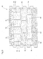
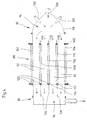
- An embodiment of a device according to the present invention for introducing pourable and / or blowable insulating particles in molded stone channels comprises at least one support surface, the support of at least to be provided with a filling and large surfaces having molded block with at least one perpendicular to the large surfaces extending channel serves, and a conveyor, which promotes pourable and / or blowable insulating particles, in particular mineral fiber with a channel flowing air stream comprises.
- the conveyor preferably has a particular bell-shaped housing, which has a supply line for the Constant pourable and / or blowable insulating particles and can be placed with the interposition of a seal on a large surface of the molded block.
- the conveyor may comprise a housing having a suction line for generating a negative pressure in the channel of the molded block for the pourable and / or blowable insulating particles to be sucked in and can be placed with the interposition of a seal on a large surface of a molded block.
- the housing can comprise an input area facing the shaped block, which has an air-permeable membrane spanning this input area, which is essentially impermeable to the pourable and / or blowable insulation particles.
- the conveying direction of the blowable insulating particles is preferably aligned substantially horizontally, wherein the channel is formed in the molded block on the output side with an air-permeable membrane.
- the membrane may be formed as a film and is preferably detachably connectable to the molded block.
- the housing preferably has a guide device, for example in the form of, at its input and / or output region facing the shaped block Baffles, up.
- the housing advantageously comprises an injection device for the addition of binding and / or impregnating agents in the flow.
- the injection device advantageously comprises at least two injection nozzles, which are arranged diametrically opposite on both sides of the supply line.
- the guide device in particular the length of the guide plates, preferably formed adjustable.
- the housing may comprise a collecting device for excess insulating particles.
- the supply line and / or the suction line preferably comprises or comprise a valve via which excess conveying air can be discharged.
- the injection device preferably has at least one storage container for binders.
- the supply line and / or the suction line are advantageously connected to a pump, in particular a vacuum pump and / or a fan.
- the present invention relates to a building, in particular a wall, consisting of at least two molded bricks according to the invention, wherein the bricks are arranged abutting with two side surfaces, wherein between the adjacently arranged molded bricks an insulating element, in particular of mineral fibers, is arranged.
- the molded blocks preferably have alternately arranged projections, in particular springs and recesses, in particular grooves, at least in the region of their abutting side surfaces.
- the insulating element is advantageously designed as a shaped body, wherein it preferably extends over approximately the entire side surface and is flush with an edge of the side surface.
- the material thickness of the insulating element is advantageously between 3 mm to 15 mm, in particular between 3 mm and 5 mm.
- the density of the insulating element is preferably in the range between 50 kg / m 3 and 120 kg / m 3 .
- the insulating element advantageously comprises at least one side an adhesion-promoting coating, so that it is firmly positioned on a molded block.
- each side face of the shaped bricks has a groove which serves to receive an insulating strip which substantially, preferably completely, fills the grooves of adjacent shaped bricks.
- the groove is preferably arranged substantially centrally in the side surface and may have different depths.
- the insulating strip advantageously has a width of the groove slightly increased material thickness, preferably between 10 mm and 70 mm, in particular between 20 mm and 40 mm.
- the groove preferably has a ratio of depth to width of 3: 1.
- the bulk density of the insulating strip is advantageously> 30 kg / m 3 .
- the insulating strip is preferably laminated on at least one large area with a heat-reflecting coating or a fiberglass mat.
- the insulating strip on a large surface may have a substantially air-impermeable coating.
- the present invention relates to a shaped brick, such as brick, especially brick, with a preferably substantially cuboid body, the two substantially parallel and spaced apart aligned large surfaces and substantially perpendicular thereto extending side surfaces and substantially parallel to the side surfaces and having substantially perpendicular to the large surfaces extending channels, wherein in at least one channel, a filling of an at least limited compressible insulating material, in particular of a mineral fiber insulation, is arranged.
- the filling has a vapor-permeable layer which is arranged together with the insulating material in the channel.
- the layer is advantageously located directly on a wall of the channel. Furthermore, a plurality of channels are preferably arranged adjacent and separated by transverse webs.
- transverse webs are preferably formed at least partially pliable.
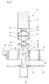
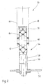
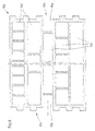
- Fig. 1 shows a partially sectioned front view of an embodiment of a first device 10 according to the present invention, which serves as a collection device for drawing a shaped body 12 into a channel 14 of a molded block 16.
- the molded block 16 is a perforated brick having channels 14, which is held by means of a gripper 18 of the device 10 to be positioned precisely such that the channels 14 of the shaped block 16 are vertical extend.
- the gripper 18 is at least horizontally, but preferably freely moved in space, so that the molded block 16 and the device 10 can be moved relative to each other so that the individual channels 14 of the molded block 16 can be filled by means of the device 10 with moldings 12.
- the molded block 16 can be optionally held by means of an alternative support, wherein the alternative support is presently formed by a perforated plate 20, the hole pattern is formed according to the channels 14 of the molded block 16.
- the device 10 is mounted on a platform 22 that is movable at least in height, but preferably freely movable in space.
- the platform 22 may for example be attached to guide rails, not shown, and is at least movable up and down by means of pneumatically or hydraulically moving piston rods or drive motors.
- the drive is preferably effected by a hydraulic drive.
- the platform 22 can also be attached to a vectorially controlled, three-dimensionally movable arm of a so-called robot in order to be able to precisely control the individual channels 14 of the molded block 16 with the aid of suitable sensors.
- the device 10 shown in FIG. 1 serves for filling a respective channel 14 of a molded block 16 with a shaped body 12.
- the device 10 can also be extended such that a plurality of channels 14 or entire rows of channels of one or more blocks 16 are simultaneously filled with corresponding moldings 12. However, this will not be discussed further below for the sake of simplicity.
- a support structure 24 is arranged, which is in the present case formed from a sleeve 26 which is connected at its upper free end fixed to a serving as a stamp plate 28 whose outer contour is smaller than that of the molded body 12 to be filled channel 14th of the molded block 16, so that the plate 28 can move through the corresponding channel 14.
- the plate 28 serves primarily to receive the shaped body 12.
- the required pressure cylinder 32 of the hydraulic drive is attached to the platform 22.
- the piston rod 30 can of course also be moved pneumatically or by means of drive motors up and down, however, as indicated previously, due to the exact positioning a hydraulic drive is preferred.
- a plurality of piston rods are movable by a single pressure cylinder, if several channels 14 of a molded block 16 are to be filled with moldings 12 at the same time.
- the piston rods can for example be attached to a common plate, which in turn is moved by a central piston rod of the impression cylinder.
- pin-shaped projections 34 are attached on both sides for coupling in each case a compression and draft-receiving linkage 36.
- the sleeve 26 is laterally open, so that the projections 34 can extend therethrough.
- corresponding, vertically extending guide slots may be provided.
- Another linkage 38 is attached to an upper guide sleeve 40, which is pushed over the sleeve 26 and guided up and down on this movable.
- the upward movement of the guide sleeve 40 is limited by the plate 28, which serves as a stop here.
- the guide sleeve 40 may alternatively be performed similar to the head 33 of the piston rod 30 within the sleeve 26.
- Both rods 36 and 38 are attached to two gripper shells 42 and 44 and give them an exact guide.
- the gripper shells 42 and 44 may for example consist of thin sheets which can accommodate the pressure forces required for the compression of the shaped body 12 without substantial deformations.
- the gripper shells 42 and 44 can be provided for stiffening with beads, which optionally form guide rails.
- plastic strips or resilient metal strips can be attached to the outside of the gripper shells 42 and 44.
- rollers or wheels can be arranged on the outside of the gripper shells 44 and 46.
- closed gripper shells 42 and 44 these can be constructed fork-shaped, wherein the prongs consist of rods or tongues made of spring steel.
- the reinforcing and guide rails as well as the tines of the forked grippers can be used in devices for the simultaneous filling of a plurality of channels 14 of a molded block 16 in each case in relation to the gripper shells 42, 44 which are moved relative to one another when opened, are arranged offset.
- the largest possible opening width can be achieved with a simultaneous filling of consecutive channels 14.
- this aspect is negligible when the device for filling only one channel 14 of a molded block 16 with a shaped body 12 is used, or if every second channel row of a molded block 16 is skipped, so that the individual gripper shells 42, 44 are not so close to each other ,
- the gripper shells 42 and 44 are angled inwardly at the lower end so that they can be easily moved into the refill channels 14 of the molded block 16.
- the device 10 is operated as follows:
- the support structure 24 For receiving the molded body 12, the support structure 24 is first brought together with the pulled-down looper shells 42 and 44 via the platform 22 in the upper position, which is shown in Fig. 1.
- the piston rod 30 moved upward, the lower linkage 36 exerts a lateral, outward pressure on the claw shells 42 and 44.
- the same is done by the upper linkage 44 after it is driven against the serving as a stop plate 28.
- the spring 46 is preferably a metal spring. Alternatively, however, an air-filled rubber cushion or a gas spring may be provided. Furthermore, it is of course possible to arrange a plurality of springs 46.
- the shaped body 12 is optionally guided or dropped by hand, by means of a corresponding task device or with the aid of a robot between the gripper shells 42 and 44 and is seated on the plate 28.
- the piston rod 30 is offset by means of the pressure cylinder 32 in a downward movement.
- the lower linkage 36 is aligned in the pulling direction.
- the platform 22 is also moved downwards, so that the angled gripper shells 42 and 44 touch the inner edges of the channels 14 of the molded block 16.
- the train of the piston rod 30 is now a sufficient counterforce on the two gripper shells 42 and 44 constructed, which now leads to the compression of the shaped body 12.
- the downward movement of the platform 22 is stopped when the plate 28 is located approximately at the level of the lower opening of the channel 14 of the molded block 16.
- the exact position is dependent on the stiffness of the insulating material of the molded body 12, but usually it is above the lower opening of the channel 14, to prevent the molded body 12 protrudes from the channel 14.
- the piston rod 30 is moved further down. Since the molded body 12 is held on the plate 28 and optionally upsetting, the gripper shells 42 and 44 are pulled past this out of the channel 14 of the molded block 16.
- the gripper shells 42 and 44 are either moved under the next channel 14 of the block 16 or the shaped block 16 is moved accordingly by means of the gripper 18. Subsequently, the support structure 24 is moved to receive a new molded body through the corresponding channel 14 of the molded block 16 upwards.
- Fig. 2 shows a partially sectioned front view of another embodiment of a device 50 according to the invention, which serves for drawing a shaped body into a channel of a molded block.
- the device 50 comprises a platform 52, which is movable by suitable means at least up and down, but preferably freely in space.
- a support structure 54 is held, which has a sleeve 56 in which two telescopically movable piston rods 58 and 60 are arranged and movable up and down.
- the actuating means for the piston rods 58 and 60 which may be, for example, pressure cylinder, are not shown in Fig. 2.
- the remaining structure of the device 50 substantially corresponds to that of the device 10 in Fig. 1, which is why will not be discussed in more detail below.
- the piston rod 60 is moved to an upper position.
- the piston rod 58 is moved upwards until the rods 62 and 64 have pushed apart the gripper shells 66 and 68.
- the piston rods 58 and 60 are pulled apart, so that the gripper shells 66 and 68 not only contactless, but even with significantly reduced thickness in the corresponding channel 14 of the molded block 16 can be fed.
- the gripper shells 66 and 68 In the lower end position of the punch-like plate 70 of the piston rod 60, the gripper shells 66 and 68 as far as it allows the channel width, moved apart and deducted from the mold body 12.
- the molded body 12 can generally protrude upwardly from the gripper shells 66 and 68 as well as laterally, so that it itself clamps during the downward movement and the frictional forces thereby developed facilitate the extraction or reduce the compression in the region of the plate 70.
- the telescopic arrangement of the piston rods 58 and 60 allows high compression of the molded body 12 with low stress on the channel inner walls, in particular the upper edges of the molded block 16 and the inevitable wear on the outer surfaces of the gripper shells 66 and 68th
- the moldings 12, which are drawn into the channels 14 of the molded blocks 16, preferably have densities in the range from 20 kg / m 3 to 120 kg / m 3 fiber mass.
- the frictional forces required for a secure clamping between at least two opposite inner walls of the holes can not be quantified directly because of the large number of types of insulating material and their inhomogeneities. However, they are achieved by a corresponding and, if necessary, easily correctable excess with respect to the compression direction.
- the oversize can be reduced with the usual contents of organic binders of 3 2% by mass with respect to the pure fiber mass with increasing bulk density. Generally standard values are approx. 1 mm to approx.
- the oversize of the moldings 12 with respect to the side surfaces lying parallel to the compression direction of the gripper shells 66, 68 depends to a great extent on their clamping effect and the compression resistance of the shaped body 12. At a low compression resistance of the molded body 12 is drawn in even at a considerable excess. If the insulation materials are less compressible, the excess is reduced to 0 or to a small undersize, if necessary, since the insulation materials compressed transversely thereto cause a slight bulging of the side walls across the thickness.
- the moldings 12 for use can be laminated on at least one surface, for example with glass fiber mats or perforated metal foils.
- Non-flammable glass fiber random webs, but also synthetic fiber random webs can serve as sliding layers. Due to their reflectivity, metal foils should reduce the radiation transmission and thus the energy transmission. Insulating moldings with radiation-reflecting films are used in particular in the room-side and thus in the heating period to be heated part of the molded block 16.
- the gripper shells 66, 68 of the collection device are arranged parallel to the longitudinal axis of the shaped stone channels. However, especially in the case of stiff rock wool insulation materials, they can also be oriented transversely thereto. Thus, the gripper shells 66, 68 can be further contracted to the respective channel center.
- the minimum channel size of the molded block 16 is technically conditioned by the size of the retraction device for the drawing of insulating moldings. With a variety of small and / or irregularly shaped holes, it is much more economical to fill them with mineral wool flakes or other blowable insulating materials.
- FIG 3 shows an example of a cross-sectional view of an embodiment of a molded block 80 according to the present invention, which is a so-called perforated brick whose channels 82 have very different geometries, but otherwise the usual outer shape.
- the moldings are formed with a density between 20 kg / m 3 and 120 kg / m 3 and can at least one side with a sliding and / or radiation-reflecting Lamination, for example, a random web, in particular a glass fiber or synthetic fiber random web or a preferably perforated metal foil be provided.
- the inner smaller channels are not filled with insulating materials. All other channels 86, in which no moldings are used, are filled with mineral wool flakes or other pourable and / or blowable insulation particles.
- the pourable and / or blowable insulation particles can be mixed with binders, in particular with inorganic water glasses, silica sol, organically modified silanes, plastic dispersions and / or thermosetting, water-soluble resins, for example phenolic resin and / or thermoplastics, the binders additionally pigments and / or or fillers.
- the pourable and / or blowable insulating particles can be produced from a mineral fiber granulate which has up to 20% by mass of binder.
- the binder in the pourable and / or blowable insulation particles is advantageously cured with microwave radiation and / or with heated air guided through the pourable and / or blowable insulation particles and / or at least one heat radiator.
- the pourable and / or blowable insulating particles can also be introduced into the channels of a given, in particular a temperature between 100 ° C and 180 ° C, preferably between 150 ° C and 180 ° C having shaped block 80.
- aerosol-like atomized oils or oil emulsions can additionally be introduced into the channels 86, in particular blown in and / or sucked in.
- the pourable and / or blowable insulation particles preferably have a density of between 45 kg / m 3 and 120 kg / m 3 in the state introduced into the molded block 80.
- An example of a corresponding blowing device is shown in FIG.
- Fig. 4 is a sectional view and shows the example of a horizontally shaped block 88, a device 90 for filling channels 92 of the block 88 with arbitrarily shaped cross-sections.
- the molded block 88 can rest on a support or be positioned by means of a gripper, which is not shown in Fig. 4.
- the device 90 comprises two independently movable heads, namely a material supply head 94 and a suction head 96.
- Both the Materialzu Fightingkopf 94 and the suction head 96 can be fixed, for example, not shown guides and means also not shown electric drives or optionally by means of pneumatically or hydraulically driven Moves piston rods and pressed from both sides according to the molded block 88.
- the heads 94 and 96 can also be moved by freely movable in space robot arms.
- the device 90 can also have a plurality of material feed heads 94 and correspondingly also suction heads 96, which are moved via a common control unit and via common guide elements.
- the supply of mineral wool flakes via the Materialzu slaughterwood 94 comprises a split sheet metal construction 98 which is pressed via a sealing ring 100 at least on the peripheral outer webs 102 and 104 of the block 88, but optionally also on the webs of a channel row or a single channel in that the gasket produced by the gasket 100 is intended to prevent the escape of conveying air and mineral wool flakes.
- the mineral wool flakes are conveyed by means of the commonly used carriers whose respective power is adapted to consumption, via one or more distribution nozzles or via several conveying lines together with corresponding connections in the direction of arrow 106 into the cavity of Materialzuseasonedkopfes 94.
- guide vanes 114, 116, 118 are arranged above the webs 108, 110, 112 of the molded block 88. These can fully reproduce the pattern with the channels to be filled.
- the height of the baffles 114, 116, 118 can be varied in order to achieve a uniform or just a selective admission of the openings of individual channel rows or individual channels 92.
- baffles 114, 116 and 118 and the congestion of mineral wool flakes before or on the webs 108, 110 and 112 is prevented, which drop after the end of the filling process and must be eliminated consuming.
- one or more bulges may be provided on the material feed head 94 in the lower part of the housing in which the excess mineral wool flakes are collected. At the beginning of the next filling process, these can then optionally be blown into the channels to be filled.
- injection nozzles 120 distributed along the circumference are provided on the material supply head 94 in the present case. If liquids are to be introduced, both injection nozzles and high-pressure nozzles with the corresponding storage containers can be installed on the conveyor.
- Suitable liquid binders are, for example, inorganic water glasses, silica sol, organically modified silanes, plastic dispersions or thermosetting, water-soluble resin mixtures.
- the components or mixtures may be added alone or together or sequentially to the mineral wool flakes or other blowable insulation materials.
- aerosol-type atomized oils or oil emulsions can be injected.
- Both the liquid inorganic and the organic binders may contain pigments and / or fillers.
- the suction head 96 of the device 90 is connected either to a pumping system, such as a vacuum pump, or to a ventilator, which produces both a sufficiently high vacuum and a sufficiently high conveying air flow. Also, the suction head 96 is sealed by means of appropriate seals 122 against the block 88 to prevent the suction of so-called false air as well as the escape of fibers safely.
- a pumping system such as a vacuum pump
- a ventilator which produces both a sufficiently high vacuum and a sufficiently high conveying air flow.
- the suction head 96 is sealed by means of appropriate seals 122 against the block 88 to prevent the suction of so-called false air as well as the escape of fibers safely.
- a screen 124 which intercepts the mineral wool flakes or non-fibrous particles contained therein. By occupying with the mineral wool flakes, a filter quickly builds up on the screen 124, which itself is highly effective.
- the suction head 96 is subdivided by means of baffles 126 or by means of fixtures adapted to the web widths of the molded block 88. In this way, similar to the baffles 114, 116 and 118, a uniform application or filling of the channels 92 of the molded block 88 is effected.
- the screen 124 can be set back so far along the baffles 126 in the suction 96, that after each filling always enough residual material remains, so that from the outset, a sufficiently high filter resistance is present.
- the vacuum and / or the exhaust air flow can be varied.
- the individual connection of individual channels 92 or rows of channels to the exhaust system, the filling of different channels 92, both in terms of time and the bulk density of the mineral wool flakes are made uniform or similar.
- the bulk density of the injected or sucked mineral wool flakes varies depending on the original floc size and the channel geometries between about 45 kg / m 3 to 120 kg / m 3 .
- the highly compressed mineral wool flakes after lifting the heads 94 and 96 is still a slight expansion, so that the insulating material from the channels 92 of the molded block 88 can swell out. By slightly brushing over the supernatant material can be finally removed.
- the mineral wool flakes can be added to binders or be subsequently sprayed onto the open end faces of the molded block 88.
- binders either dry atmospherically or are solidified, especially in the near-surface zones, by virtue of the fact that the shaped brick 88 is pushed past area-effect radiant heaters.
- other drying methods are conceivable.
- the additional impregnation with oil should increase the often required water repellency of the mineral wool flakes or bring after the addition of binders to the old state.
- blowable insulation particles may be introduced into the channels 92 of the molding block 88, such as cellulose fibers, expanded glass, pumice, polystyrene beads or the like. These blowable insulating particles can also be impregnated with binders and connected to one another and to the inner walls of the channels 92 of the molded block 88. In most cases, even the form-fitting bond with the inner walls of the holes is sufficient to prevent falling not too heavy masses.
- FIG. 5 shows a cross-sectional view of another embodiment of a molded block 130 according to the invention.
- the channels 132 of the molded block 130 are filled with insulating material by first blowing in mineral wool flakes which form a plug 134 approximately 20 mm to 50 mm high, which is bound by a binder is fixed. Subsequently, unbound loose particles 136 are filled, the final conclusion in turn a plug 138 bound from Mineral wool flakes forms, which is shown on the left side in Fig. 5.
- the plugs closing off a channel 132 may also be formed, for example, from shaped articles, such as rockwool moldings with densities> 40 kg / m 3 , as shown in FIG. 5 by the plugs designated by the reference numbers 140 and 142.
- FIG. 6 shows a further embodiment of a molded block 150 according to the invention, which has any channel pattern conceived taking into consideration aspects of heat and / or sound insulation.
- the channels 152 of the molded block 150 may optionally be filled with insulating materials.
- the side surfaces 154 of the molded block 150 are formed toothed, whereby an accurate positioning of adjacent blocks 150 is ensured relative to each other.
- Grooves 156 extending in each case over the height of the molded block 150 are formed in the side surfaces 154, into which, preferably after the setting of the molded block 150, an insulating molded article (not shown) with, for example, a rectangular cross section can be inserted.
- the insulating molded body can already be clamped at the factory, but there is a risk that it will be damaged in the handling of the block 150 and then no longer fits into the corresponding groove 156 of the adjacent block 150 to be arranged.
- This insulating molded body is intended to reduce heat as well as shadow bridge effect of the butt joints.
- the grooves 156 can each be arranged in the middle of the toothed side surface 154 of the molded block 150, to allow a symmetrical toothing. However, it is also possible that the grooves 154 are arranged off-center. The depth of the grooves 156 may be equal or different on both sides.
- the thickness of the preferably made of mineral wool insulating molding is about 10 mm to about 70 mm, preferably about 20 mm to 40 mm.
- the cross-section is usually rectangular, the width-to-thickness ratio mostly> 3: 1. In order to achieve sufficient rigidity, the bulk density should exceed> 30 kg / m 3 .
- the insulating molded body can be laminated on one or both sides with heat-reflecting layers or fiberglass nonwovens. Furthermore, it may have an air-inhibiting coating alone or in addition to the aforementioned laminations. This air-inhibiting coating is preferably directed outwards.
- FIG. 7 shows a cross-sectional view of another embodiment of two adjacently arranged molded bricks 160 according to the present invention.
- the molded blocks 160 likewise have moldings 160 made of insulating material Channels 162 and provided with a toothing end faces 166. Between the toothed end faces 166 of the adjacently arranged molded blocks 160, a shaped body, preferably formed of rock wool, is provided which has a form corresponding to the serrations of the end faces 166 of the adjacently arranged shaped blocks 160.
- the height of the molded body 168 corresponds to the height of the molded blocks 160.
- the thickness of the molded body 168 is about 3 mm to 15 mm, preferably about 3 mm to 5 mm.
- the apparent density is in a range of preferably between 50 kg / m 3 and 120 kg / m 3 .
- the mold body 168 may be flush with the side surfaces of the adjacently located mold bricks 160, see reference numeral 170. This embodiment is appropriate when the outer surface of the outer wall made of these mold bricks 160 is covered, for example, with another insulating layer or only with a ventilated clothing.
- the molded body 168 may alternatively spring back slightly on the usually plastered inner wall surface, see reference numeral 172.
- One or both side edges of the molding 168 may be provided with adhesion promoting primers.
- adhesion-promoting primers or layers By means of these adhesion-promoting primers or layers, a non-positive bond with the plaster layers is to be achieved.
- Fig. 8 shows a cross-sectional view of another embodiment of a molded block 180 according to the invention with a two-part construction.
- the first part 182 is formed with a high bulk density and smaller channels 184, while the second part 186, which is preferably directed outwardly, has a lower bulk density and correspondingly a lower compressive strength, but a higher thermal resistance.
- the insulating shaped body 188 and insulating flakes 190 are preferably introduced into the corresponding channels of the second part 186.
- the two parts 182 and 186 of the molded block 190 are prepared as usual, each in a separate extruder and joined together by applying a slip on the adhesive surfaces, dried and fired.
- flat grooves may be formed in the wall of the rear part, in which the webs of the part to be bonded are introduced, which is not shown here.
- both parts 182 and 186 of the molded block 180 can be glued to high-strength synthetic resins.
- the minimum width of the rear part 182 of the molded block 180 is preferably 3 17.5 cm.
- the bonding surfaces are treated with suitable primers, that is, sufficiently deep-primed. This pretreatment is known in principle. If multi-component resins with sufficient reaction rate and heat release are used, a post-curing is unnecessary. Prophylactically, however, the bonding surfaces are heated and, if necessary, also after the application of the adhesive aftertreated, for example, to obtain a consistently solid compound at lower temperatures in the production halls.
- Fig. 9 shows a cross-sectional view of another embodiment of a molded block 192 according to the invention, the channels 194 are at least partially filled with segments 196 and 198 of mineral wool pipe shells.
- pipe shells are preferred with a sufficiently high rigidity in the axial direction.
- the segments 196 have the shape of the channels 194 corresponding to beveled longitudinal side surfaces.
- the tubing segments can be stretched along the tendon and thus easily inserted into the channels 194.
- the small thicknesses of the side surfaces do not lead to high frictional forces and excessive abrasion, so that a tight fit is ensured.
- the tubing segments 196, 198 may be divided in height and inserted into the channels 194 from both sides.
- the pipe shell segments 194 and 196 serve primarily the airborne sound damping. You should therefore be placed at any angle to the outer surfaces, so that they point in different directions.
- Tubular shell segments are particularly suitable for filling round or elliptical holes. They may be laminated with perforated metal foils and / or with air-permeable nonwovens or coated with sealing paints, plasters or the like.
Landscapes
- Engineering & Computer Science (AREA)
- Structural Engineering (AREA)
- Chemical & Material Sciences (AREA)
- Ceramic Engineering (AREA)
- Mechanical Engineering (AREA)
- Architecture (AREA)
- Physics & Mathematics (AREA)
- Electromagnetism (AREA)
- Civil Engineering (AREA)
- Building Environments (AREA)
- Finishing Walls (AREA)
- Moulds, Cores, Or Mandrels (AREA)
Applications Claiming Priority (2)
| Application Number | Priority Date | Filing Date | Title |
|---|---|---|---|
| DE102005034807 | 2005-07-21 | ||
| DE102006022516A DE102006022516A1 (de) | 2005-07-21 | 2006-05-15 | Verfahren und Vorrichtung zur Herstellung eines Formsteins, Formstein und Bauwerk bestehend aus mindestens zwei Formsteinen |
Publications (3)
| Publication Number | Publication Date |
|---|---|
| EP1745902A2 true EP1745902A2 (fr) | 2007-01-24 |
| EP1745902A3 EP1745902A3 (fr) | 2008-04-23 |
| EP1745902B1 EP1745902B1 (fr) | 2016-01-13 |
Family
ID=37198183
Family Applications (1)
| Application Number | Title | Priority Date | Filing Date |
|---|---|---|---|
| EP06015133.9A Not-in-force EP1745902B1 (fr) | 2005-07-21 | 2006-07-20 | Procédé pour la fabrication d'une brique moulée |
Country Status (5)
| Country | Link |
|---|---|
| EP (1) | EP1745902B1 (fr) |
| DE (1) | DE102006022516A1 (fr) |
| ES (1) | ES2564170T3 (fr) |
| HU (1) | HUE027193T2 (fr) |
| PL (1) | PL1745902T3 (fr) |
Cited By (4)
| Publication number | Priority date | Publication date | Assignee | Title |
|---|---|---|---|---|
| FR2963034A1 (fr) * | 2010-07-22 | 2012-01-27 | Tarmac Materiaux De Construction | Procede et dispositif de fabrication d'au moins un bloc de construction integrant un materiau isolant |
| CZ304720B6 (cs) * | 2010-11-02 | 2014-09-10 | HELUZ cihlářský průmysl v.o.s. | Způsob plnění dutinových cihelných tvarovek sypkým izolačním materiálem a zařízení k provádění tohoto způsobu |
| EP3768908A1 (fr) * | 2018-03-20 | 2021-01-27 | Ceramix AG | Produit de construction |
| DE102024000821A1 (de) | 2024-03-12 | 2025-09-18 | X2024 Patente UG (haftungsbeschränkt) i.G. | Flammfeste, hochisolierende und auch schwerlastfähige Bausteine in Leichtbauweise |
Families Citing this family (4)
| Publication number | Priority date | Publication date | Assignee | Title |
|---|---|---|---|---|
| DE102007031906A1 (de) | 2007-07-09 | 2009-01-15 | Grenzebach Maschinenbau Gmbh | Vorrichtung und Verfahren zum industriellen Befüllen von unterschiedlich strukturierten Hohlräumen in Bausteinen |
| DE102010045927B4 (de) * | 2010-09-21 | 2012-12-20 | Keller Hcw Gmbh | Vorrichtung zum Einbringen von Isoliermaterialien in Lochziegel |
| DE102015108255A1 (de) * | 2015-05-26 | 2016-12-01 | Michael Kellerer | Verfahren zum Erstellen einer mehrschichtigen Wand, mehrschichtige Wand, hierfür verwendeter Langloch- oder Hochlochziegel sowie hieraus ausgebildetes Gebäude |
| BE1026839B1 (nl) * | 2018-12-06 | 2020-07-06 | Debinco Nv | Kimblok voor dubbelwandig muurwerk, werkwijze voor het vervaardigen ervan, en gebruik ervan |
Citations (4)
| Publication number | Priority date | Publication date | Assignee | Title |
|---|---|---|---|---|
| DE4101125A1 (de) | 1991-01-16 | 1992-07-23 | Mantel Juval | Verbesserte, schalldaemmende ziegel |
| DE10034342A1 (de) | 1999-09-29 | 2001-05-03 | Xaver Winklmann Ziegelwerk Roe | Ziegel |
| EP0741827B1 (fr) | 1994-01-28 | 2003-04-02 | Rockwool International A/S | Procede et element isolant et atelier de fabrication et d'emballage |
| DE10217548A1 (de) | 2002-04-19 | 2003-11-13 | Stefan Geyer | Vorrichtung und Maschine zum Einbringen von Mineralwolle in die Hohlräume stranggepresster Lochziegel |
Family Cites Families (4)
| Publication number | Priority date | Publication date | Assignee | Title |
|---|---|---|---|---|
| US3343251A (en) * | 1963-10-07 | 1967-09-26 | Natco Corp | Method for filling structural clay tile |
| AT348396B (de) * | 1977-07-29 | 1979-02-12 | Kruegler Emil Dipl Ing | Vorrichtung zur einbringung einer elastischen isolationsschichte zwischen zwei bauteile |
| AT367680B (de) * | 1979-05-07 | 1982-07-26 | Quehenberger Andreas | Vorrichtung zum einsetzen von daemmplatten in entsprechende hohlraeume von bauelementen |
| SE8004635L (sv) * | 1980-06-23 | 1981-12-24 | Ferila Lettblock Ab | Maskin for isolering av halblock |
-
2006
- 2006-05-15 DE DE102006022516A patent/DE102006022516A1/de not_active Withdrawn
- 2006-07-20 EP EP06015133.9A patent/EP1745902B1/fr not_active Not-in-force
- 2006-07-20 PL PL06015133.9T patent/PL1745902T3/pl unknown
- 2006-07-20 HU HUE06015133A patent/HUE027193T2/en unknown
- 2006-07-20 ES ES06015133.9T patent/ES2564170T3/es active Active
Patent Citations (4)
| Publication number | Priority date | Publication date | Assignee | Title |
|---|---|---|---|---|
| DE4101125A1 (de) | 1991-01-16 | 1992-07-23 | Mantel Juval | Verbesserte, schalldaemmende ziegel |
| EP0741827B1 (fr) | 1994-01-28 | 2003-04-02 | Rockwool International A/S | Procede et element isolant et atelier de fabrication et d'emballage |
| DE10034342A1 (de) | 1999-09-29 | 2001-05-03 | Xaver Winklmann Ziegelwerk Roe | Ziegel |
| DE10217548A1 (de) | 2002-04-19 | 2003-11-13 | Stefan Geyer | Vorrichtung und Maschine zum Einbringen von Mineralwolle in die Hohlräume stranggepresster Lochziegel |
Cited By (5)
| Publication number | Priority date | Publication date | Assignee | Title |
|---|---|---|---|---|
| FR2963034A1 (fr) * | 2010-07-22 | 2012-01-27 | Tarmac Materiaux De Construction | Procede et dispositif de fabrication d'au moins un bloc de construction integrant un materiau isolant |
| CZ304720B6 (cs) * | 2010-11-02 | 2014-09-10 | HELUZ cihlářský průmysl v.o.s. | Způsob plnění dutinových cihelných tvarovek sypkým izolačním materiálem a zařízení k provádění tohoto způsobu |
| EP3768908A1 (fr) * | 2018-03-20 | 2021-01-27 | Ceramix AG | Produit de construction |
| EP3768908B1 (fr) * | 2018-03-20 | 2025-03-05 | Ceramix AG | Paroi ou enveloppe de bâtiment |
| DE102024000821A1 (de) | 2024-03-12 | 2025-09-18 | X2024 Patente UG (haftungsbeschränkt) i.G. | Flammfeste, hochisolierende und auch schwerlastfähige Bausteine in Leichtbauweise |
Also Published As
| Publication number | Publication date |
|---|---|
| EP1745902B1 (fr) | 2016-01-13 |
| PL1745902T3 (pl) | 2016-09-30 |
| HUE027193T2 (en) | 2016-10-28 |
| EP1745902A3 (fr) | 2008-04-23 |
| DE102006022516A1 (de) | 2007-02-01 |
| ES2564170T3 (es) | 2016-03-18 |
Similar Documents
| Publication | Publication Date | Title |
|---|---|---|
| EP1745901B1 (fr) | Procédé et dispositif pour la fabrication d'une brique moulée | |
| EP3128103B1 (fr) | Tapis de desolidarisation | |
| DE102013007800B4 (de) | Trockenmörtelplatte sowie Verfahren und Verwendung einer Vorrichtung zu deren Herstellung | |
| DE10020956B4 (de) | Mauerstein und Verfahren zu seiner Herstellung | |
| EP1745902B1 (fr) | Procédé pour la fabrication d'une brique moulée | |
| EP2395171B2 (fr) | Panneau de construction ainsi que procédé et dispositif de fabrication d'un panneau de construction | |
| EP3466625A1 (fr) | Plaque composite et sa fabrication | |
| AT405204B (de) | Wandplatte sowie verfahren zur herstellung einer wandplatte | |
| EP2860319A1 (fr) | Composé d'isolation thermique et zone composite d'isolation thermique ainsi que structure murale comprenant le composé d'isolation thermique ou la zone composite d'isolation thermique et procédé de fabrication de structures murales | |
| EP2758610B1 (fr) | Méthode pour fabriquer un panneau de construction | |
| EP3156383B1 (fr) | Procédé de fabrication d'une mousse inorganique | |
| EP0378217B1 (fr) | Brique perforée et procédé pour l'érection d'une paroi insonore | |
| EP1708876B1 (fr) | Procede de fabrication d'une bande de materiau isolant a partir de fibres minerales et bande de materiau isolant ainsi obtenue | |
| DE3530138A1 (de) | Sandwich-baustein fuer aussenmauerwerke | |
| EP2765251B1 (fr) | Composite d'isolation thermique en forme de plaque, et zones de composite d'isolation thermique, en particulier zones de plaque d'isolation thermique, comprenant des composites d'isolation thermique en forme de plaques, procédé de fabrication de composites d'isolation thermique et utilisation de composites d'isolation thermique pour l'isolation thermique de bâtiments | |
| WO2019180605A1 (fr) | Produit de construction | |
| EP1559844B1 (fr) | Element d' isolation et système composite d' isolation thermique | |
| EP0939173B2 (fr) | Procédé de fabrication d'un panneau isolant en fibres minérales et panneau isolant | |
| DE4432110A1 (de) | Bauplatte aus Kunststoff | |
| WO1994017258A1 (fr) | Element de construction | |
| DE102006019796A1 (de) | Mauerwerksandwichelement und Verfahren zu seiner Herstellung | |
| NZ524021A (en) | Molding shaped cavities into mineral fiber panels during conveying and compression operation | |
| EP1004716A2 (fr) | Panneau d'isolation | |
| EP2395164A2 (fr) | Composant pour un bâtiment, notamment composant de mur, de plafond ou de toit et procédé de fabrication associé | |
| EP0343148A2 (fr) | Fibre en matière plastique traitée spécialement pour la modification de matériaux de construction |
Legal Events
| Date | Code | Title | Description |
|---|---|---|---|
| PUAI | Public reference made under article 153(3) epc to a published international application that has entered the european phase |
Free format text: ORIGINAL CODE: 0009012 |
|
| AK | Designated contracting states |
Kind code of ref document: A2 Designated state(s): AT BE BG CH CY CZ DE DK EE ES FI FR GB GR HU IE IS IT LI LT LU LV MC NL PL PT RO SE SI SK TR |
|
| AX | Request for extension of the european patent |
Extension state: AL BA HR MK YU |
|
| PUAL | Search report despatched |
Free format text: ORIGINAL CODE: 0009013 |
|
| AK | Designated contracting states |
Kind code of ref document: A3 Designated state(s): AT BE BG CH CY CZ DE DK EE ES FI FR GB GR HU IE IS IT LI LT LU LV MC NL PL PT RO SE SI SK TR |
|
| AX | Request for extension of the european patent |
Extension state: AL BA HR MK RS |
|
| 17P | Request for examination filed |
Effective date: 20081023 |
|
| AKX | Designation fees paid |
Designated state(s): AT BE BG CH CY CZ DE DK EE ES FI FR GB GR HU IE IS IT LI LT LU LV MC NL PL PT RO SE SI SK TR |
|
| 17Q | First examination report despatched |
Effective date: 20090709 |
|
| RAP1 | Party data changed (applicant data changed or rights of an application transferred) |
Owner name: ROCKWOOL INTERNATIONAL A/S |
|
| REG | Reference to a national code |
Ref country code: DE Ref legal event code: R079 Ref document number: 502006014711 Country of ref document: DE Free format text: PREVIOUS MAIN CLASS: B28B0011040000 Ipc: E04B0002160000 |
|
| GRAP | Despatch of communication of intention to grant a patent |
Free format text: ORIGINAL CODE: EPIDOSNIGR1 |
|
| RIC1 | Information provided on ipc code assigned before grant |
Ipc: E04B 2/16 20060101AFI20150710BHEP Ipc: B28B 11/04 20060101ALI20150710BHEP |
|
| INTG | Intention to grant announced |
Effective date: 20150731 |
|
| GRAS | Grant fee paid |
Free format text: ORIGINAL CODE: EPIDOSNIGR3 |
|
| GRAA | (expected) grant |
Free format text: ORIGINAL CODE: 0009210 |
|
| AK | Designated contracting states |
Kind code of ref document: B1 Designated state(s): AT BE BG CH CY CZ DE DK EE ES FI FR GB GR HU IE IS IT LI LT LU LV MC NL PL PT RO SE SI SK TR |
|
| REG | Reference to a national code |
Ref country code: GB Ref legal event code: FG4D Free format text: NOT ENGLISH |
|
| REG | Reference to a national code |
Ref country code: CH Ref legal event code: EP |
|
| REG | Reference to a national code |
Ref country code: IE Ref legal event code: FG4D Free format text: LANGUAGE OF EP DOCUMENT: GERMAN |
|
| REG | Reference to a national code |
Ref country code: AT Ref legal event code: REF Ref document number: 770627 Country of ref document: AT Kind code of ref document: T Effective date: 20160215 |
|
| REG | Reference to a national code |
Ref country code: DE Ref legal event code: R096 Ref document number: 502006014711 Country of ref document: DE |
|
| REG | Reference to a national code |
Ref country code: ES Ref legal event code: FG2A Ref document number: 2564170 Country of ref document: ES Kind code of ref document: T3 Effective date: 20160318 |
|
| REG | Reference to a national code |
Ref country code: NL Ref legal event code: FP |
|
| REG | Reference to a national code |
Ref country code: CH Ref legal event code: NV Representative=s name: FIAMMENGHI-FIAMMENGHI, CH |
|
| REG | Reference to a national code |
Ref country code: LT Ref legal event code: MG4D |
|
| REG | Reference to a national code |
Ref country code: FR Ref legal event code: PLFP Year of fee payment: 11 |
|
| PG25 | Lapsed in a contracting state [announced via postgrant information from national office to epo] |
Ref country code: FI Free format text: LAPSE BECAUSE OF FAILURE TO SUBMIT A TRANSLATION OF THE DESCRIPTION OR TO PAY THE FEE WITHIN THE PRESCRIBED TIME-LIMIT Effective date: 20160113 Ref country code: GR Free format text: LAPSE BECAUSE OF FAILURE TO SUBMIT A TRANSLATION OF THE DESCRIPTION OR TO PAY THE FEE WITHIN THE PRESCRIBED TIME-LIMIT Effective date: 20160414 |
|
| REG | Reference to a national code |
Ref country code: SK Ref legal event code: T3 Ref document number: E 20648 Country of ref document: SK |
|
| PG25 | Lapsed in a contracting state [announced via postgrant information from national office to epo] |
Ref country code: IS Free format text: LAPSE BECAUSE OF FAILURE TO SUBMIT A TRANSLATION OF THE DESCRIPTION OR TO PAY THE FEE WITHIN THE PRESCRIBED TIME-LIMIT Effective date: 20160513 Ref country code: LV Free format text: LAPSE BECAUSE OF FAILURE TO SUBMIT A TRANSLATION OF THE DESCRIPTION OR TO PAY THE FEE WITHIN THE PRESCRIBED TIME-LIMIT Effective date: 20160113 Ref country code: SE Free format text: LAPSE BECAUSE OF FAILURE TO SUBMIT A TRANSLATION OF THE DESCRIPTION OR TO PAY THE FEE WITHIN THE PRESCRIBED TIME-LIMIT Effective date: 20160113 Ref country code: PT Free format text: LAPSE BECAUSE OF FAILURE TO SUBMIT A TRANSLATION OF THE DESCRIPTION OR TO PAY THE FEE WITHIN THE PRESCRIBED TIME-LIMIT Effective date: 20160513 Ref country code: LT Free format text: LAPSE BECAUSE OF FAILURE TO SUBMIT A TRANSLATION OF THE DESCRIPTION OR TO PAY THE FEE WITHIN THE PRESCRIBED TIME-LIMIT Effective date: 20160113 |
|
| REG | Reference to a national code |
Ref country code: DE Ref legal event code: R097 Ref document number: 502006014711 Country of ref document: DE |
|
| REG | Reference to a national code |
Ref country code: HU Ref legal event code: AG4A Ref document number: E027193 Country of ref document: HU |
|
| PG25 | Lapsed in a contracting state [announced via postgrant information from national office to epo] |
Ref country code: EE Free format text: LAPSE BECAUSE OF FAILURE TO SUBMIT A TRANSLATION OF THE DESCRIPTION OR TO PAY THE FEE WITHIN THE PRESCRIBED TIME-LIMIT Effective date: 20160113 Ref country code: DK Free format text: LAPSE BECAUSE OF FAILURE TO SUBMIT A TRANSLATION OF THE DESCRIPTION OR TO PAY THE FEE WITHIN THE PRESCRIBED TIME-LIMIT Effective date: 20160113 |
|
| PLBE | No opposition filed within time limit |
Free format text: ORIGINAL CODE: 0009261 |
|
| STAA | Information on the status of an ep patent application or granted ep patent |
Free format text: STATUS: NO OPPOSITION FILED WITHIN TIME LIMIT |
|
| PG25 | Lapsed in a contracting state [announced via postgrant information from national office to epo] |
Ref country code: RO Free format text: LAPSE BECAUSE OF FAILURE TO SUBMIT A TRANSLATION OF THE DESCRIPTION OR TO PAY THE FEE WITHIN THE PRESCRIBED TIME-LIMIT Effective date: 20160113 |
|
| 26N | No opposition filed |
Effective date: 20161014 |
|
| PG25 | Lapsed in a contracting state [announced via postgrant information from national office to epo] |
Ref country code: BG Free format text: LAPSE BECAUSE OF FAILURE TO SUBMIT A TRANSLATION OF THE DESCRIPTION OR TO PAY THE FEE WITHIN THE PRESCRIBED TIME-LIMIT Effective date: 20160413 Ref country code: SI Free format text: LAPSE BECAUSE OF FAILURE TO SUBMIT A TRANSLATION OF THE DESCRIPTION OR TO PAY THE FEE WITHIN THE PRESCRIBED TIME-LIMIT Effective date: 20160113 |
|
| GBPC | Gb: european patent ceased through non-payment of renewal fee |
Effective date: 20160720 |
|
| PG25 | Lapsed in a contracting state [announced via postgrant information from national office to epo] |
Ref country code: MC Free format text: LAPSE BECAUSE OF FAILURE TO SUBMIT A TRANSLATION OF THE DESCRIPTION OR TO PAY THE FEE WITHIN THE PRESCRIBED TIME-LIMIT Effective date: 20160113 |
|
| REG | Reference to a national code |
Ref country code: IE Ref legal event code: MM4A |
|
| PG25 | Lapsed in a contracting state [announced via postgrant information from national office to epo] |
Ref country code: GB Free format text: LAPSE BECAUSE OF NON-PAYMENT OF DUE FEES Effective date: 20160720 |
|
| REG | Reference to a national code |
Ref country code: FR Ref legal event code: PLFP Year of fee payment: 12 |
|
| PG25 | Lapsed in a contracting state [announced via postgrant information from national office to epo] |
Ref country code: IE Free format text: LAPSE BECAUSE OF NON-PAYMENT OF DUE FEES Effective date: 20160720 |
|
| PG25 | Lapsed in a contracting state [announced via postgrant information from national office to epo] |
Ref country code: LU Free format text: LAPSE BECAUSE OF NON-PAYMENT OF DUE FEES Effective date: 20160720 |
|
| PG25 | Lapsed in a contracting state [announced via postgrant information from national office to epo] |
Ref country code: CY Free format text: LAPSE BECAUSE OF FAILURE TO SUBMIT A TRANSLATION OF THE DESCRIPTION OR TO PAY THE FEE WITHIN THE PRESCRIBED TIME-LIMIT Effective date: 20160113 |
|
| PG25 | Lapsed in a contracting state [announced via postgrant information from national office to epo] |
Ref country code: TR Free format text: LAPSE BECAUSE OF FAILURE TO SUBMIT A TRANSLATION OF THE DESCRIPTION OR TO PAY THE FEE WITHIN THE PRESCRIBED TIME-LIMIT Effective date: 20160113 |
|
| REG | Reference to a national code |
Ref country code: FR Ref legal event code: PLFP Year of fee payment: 13 |
|
| REG | Reference to a national code |
Ref country code: DE Ref legal event code: R082 Ref document number: 502006014711 Country of ref document: DE Representative=s name: KILBURN & STRODE LLP, NL |
|
| PGFP | Annual fee paid to national office [announced via postgrant information from national office to epo] |
Ref country code: NL Payment date: 20210726 Year of fee payment: 16 |
|
| PGFP | Annual fee paid to national office [announced via postgrant information from national office to epo] |
Ref country code: FR Payment date: 20210726 Year of fee payment: 16 Ref country code: CZ Payment date: 20210712 Year of fee payment: 16 Ref country code: AT Payment date: 20210702 Year of fee payment: 16 Ref country code: IT Payment date: 20210721 Year of fee payment: 16 |
|
| PGFP | Annual fee paid to national office [announced via postgrant information from national office to epo] |
Ref country code: ES Payment date: 20210802 Year of fee payment: 16 Ref country code: SK Payment date: 20210701 Year of fee payment: 16 Ref country code: BE Payment date: 20210727 Year of fee payment: 16 Ref country code: CH Payment date: 20210804 Year of fee payment: 16 Ref country code: DE Payment date: 20210728 Year of fee payment: 16 Ref country code: PL Payment date: 20210705 Year of fee payment: 16 Ref country code: HU Payment date: 20210714 Year of fee payment: 16 |
|
| REG | Reference to a national code |
Ref country code: DE Ref legal event code: R119 Ref document number: 502006014711 Country of ref document: DE |
|
| REG | Reference to a national code |
Ref country code: CH Ref legal event code: PL |
|
| REG | Reference to a national code |
Ref country code: NL Ref legal event code: MM Effective date: 20220801 |
|
| REG | Reference to a national code |
Ref country code: SK Ref legal event code: MM4A Ref document number: E 20648 Country of ref document: SK Effective date: 20220720 Ref country code: AT Ref legal event code: MM01 Ref document number: 770627 Country of ref document: AT Kind code of ref document: T Effective date: 20220720 |
|
| REG | Reference to a national code |
Ref country code: BE Ref legal event code: MM Effective date: 20220731 |
|
| PG25 | Lapsed in a contracting state [announced via postgrant information from national office to epo] |
Ref country code: LI Free format text: LAPSE BECAUSE OF NON-PAYMENT OF DUE FEES Effective date: 20220731 Ref country code: FR Free format text: LAPSE BECAUSE OF NON-PAYMENT OF DUE FEES Effective date: 20220731 Ref country code: CZ Free format text: LAPSE BECAUSE OF NON-PAYMENT OF DUE FEES Effective date: 20220720 Ref country code: CH Free format text: LAPSE BECAUSE OF NON-PAYMENT OF DUE FEES Effective date: 20220731 Ref country code: AT Free format text: LAPSE BECAUSE OF NON-PAYMENT OF DUE FEES Effective date: 20220720 |
|
| PG25 | Lapsed in a contracting state [announced via postgrant information from national office to epo] |
Ref country code: SK Free format text: LAPSE BECAUSE OF NON-PAYMENT OF DUE FEES Effective date: 20220720 Ref country code: HU Free format text: LAPSE BECAUSE OF NON-PAYMENT OF DUE FEES Effective date: 20220721 Ref country code: DE Free format text: LAPSE BECAUSE OF NON-PAYMENT OF DUE FEES Effective date: 20230201 Ref country code: BE Free format text: LAPSE BECAUSE OF NON-PAYMENT OF DUE FEES Effective date: 20220731 |
|
| PG25 | Lapsed in a contracting state [announced via postgrant information from national office to epo] |
Ref country code: NL Free format text: LAPSE BECAUSE OF NON-PAYMENT OF DUE FEES Effective date: 20220801 |
|
| PG25 | Lapsed in a contracting state [announced via postgrant information from national office to epo] |
Ref country code: IT Free format text: LAPSE BECAUSE OF NON-PAYMENT OF DUE FEES Effective date: 20220720 |
|
| REG | Reference to a national code |
Ref country code: ES Ref legal event code: FD2A Effective date: 20230829 |
|
| PG25 | Lapsed in a contracting state [announced via postgrant information from national office to epo] |
Ref country code: ES Free format text: LAPSE BECAUSE OF NON-PAYMENT OF DUE FEES Effective date: 20220721 |
|
| PG25 | Lapsed in a contracting state [announced via postgrant information from national office to epo] |
Ref country code: PL Free format text: LAPSE BECAUSE OF NON-PAYMENT OF DUE FEES Effective date: 20220720 |