EP1747850A2 - Vorrichtung und Verfahren zur Herstellung von Schwabbelbänder - Google Patents
Vorrichtung und Verfahren zur Herstellung von Schwabbelbänder Download PDFInfo
- Publication number
- EP1747850A2 EP1747850A2 EP06253873A EP06253873A EP1747850A2 EP 1747850 A2 EP1747850 A2 EP 1747850A2 EP 06253873 A EP06253873 A EP 06253873A EP 06253873 A EP06253873 A EP 06253873A EP 1747850 A2 EP1747850 A2 EP 1747850A2
- Authority
- EP
- European Patent Office
- Prior art keywords
- buff
- tapes
- tape
- guide roller
- roller
- Prior art date
- Legal status (The legal status is an assumption and is not a legal conclusion. Google has not performed a legal analysis and makes no representation as to the accuracy of the status listed.)
- Granted
Links
- 238000000034 method Methods 0.000 title claims description 18
- 230000006835 compression Effects 0.000 claims abstract description 31
- 238000007906 compression Methods 0.000 claims abstract description 31
- 239000002245 particle Substances 0.000 claims abstract description 24
- 239000000758 substrate Substances 0.000 abstract description 7
- 238000004804 winding Methods 0.000 abstract description 6
- 238000009499 grossing Methods 0.000 abstract description 3
- 238000005498 polishing Methods 0.000 abstract description 3
- 239000000463 material Substances 0.000 description 7
- 238000004519 manufacturing process Methods 0.000 description 6
- 239000004744 fabric Substances 0.000 description 4
- JOYRKODLDBILNP-UHFFFAOYSA-N Ethyl urethane Chemical compound CCOC(N)=O JOYRKODLDBILNP-UHFFFAOYSA-N 0.000 description 2
- 238000000576 coating method Methods 0.000 description 2
- 230000002093 peripheral effect Effects 0.000 description 2
- OKTJSMMVPCPJKN-UHFFFAOYSA-N Carbon Chemical compound [C] OKTJSMMVPCPJKN-UHFFFAOYSA-N 0.000 description 1
- 239000004677 Nylon Substances 0.000 description 1
- 229910000831 Steel Inorganic materials 0.000 description 1
- 230000002159 abnormal effect Effects 0.000 description 1
- 229910052782 aluminium Inorganic materials 0.000 description 1
- XAGFODPZIPBFFR-UHFFFAOYSA-N aluminium Chemical compound [Al] XAGFODPZIPBFFR-UHFFFAOYSA-N 0.000 description 1
- 239000011230 binding agent Substances 0.000 description 1
- 229910052799 carbon Inorganic materials 0.000 description 1
- 239000011248 coating agent Substances 0.000 description 1
- 239000011521 glass Substances 0.000 description 1
- 230000001050 lubricating effect Effects 0.000 description 1
- 229910052751 metal Inorganic materials 0.000 description 1
- 239000002184 metal Substances 0.000 description 1
- 229920001778 nylon Polymers 0.000 description 1
- TWNQGVIAIRXVLR-UHFFFAOYSA-N oxo(oxoalumanyloxy)alumane Chemical compound O=[Al]O[Al]=O TWNQGVIAIRXVLR-UHFFFAOYSA-N 0.000 description 1
- 229920000728 polyester Polymers 0.000 description 1
- 230000001681 protective effect Effects 0.000 description 1
- 229910052710 silicon Inorganic materials 0.000 description 1
- 239000010703 silicon Substances 0.000 description 1
- 239000010959 steel Substances 0.000 description 1
Images

Classifications
-
- B—PERFORMING OPERATIONS; TRANSPORTING
- B24—GRINDING; POLISHING
- B24D—TOOLS FOR GRINDING, BUFFING OR SHARPENING
- B24D11/00—Constructional features of flexible abrasive materials; Special features in the manufacture of such materials
- B24D11/008—Finishing manufactured abrasive sheets, e.g. cutting, deforming
-
- B—PERFORMING OPERATIONS; TRANSPORTING
- B08—CLEANING
- B08B—CLEANING IN GENERAL; PREVENTION OF FOULING IN GENERAL
- B08B1/00—Cleaning by methods involving the use of tools
- B08B1/30—Cleaning by methods involving the use of tools by movement of cleaning members over a surface
-
- B—PERFORMING OPERATIONS; TRANSPORTING
- B26—HAND CUTTING TOOLS; CUTTING; SEVERING
- B26D—CUTTING; DETAILS COMMON TO MACHINES FOR PERFORATING, PUNCHING, CUTTING-OUT, STAMPING-OUT OR SEVERING
- B26D1/00—Cutting through work characterised by the nature or movement of the cutting member or particular materials not otherwise provided for; Apparatus or machines therefor; Cutting members therefor
- B26D1/01—Cutting through work characterised by the nature or movement of the cutting member or particular materials not otherwise provided for; Apparatus or machines therefor; Cutting members therefor involving a cutting member which does not travel with the work
- B26D1/12—Cutting through work characterised by the nature or movement of the cutting member or particular materials not otherwise provided for; Apparatus or machines therefor; Cutting members therefor involving a cutting member which does not travel with the work having a cutting member moving about an axis
- B26D1/14—Cutting through work characterised by the nature or movement of the cutting member or particular materials not otherwise provided for; Apparatus or machines therefor; Cutting members therefor involving a cutting member which does not travel with the work having a cutting member moving about an axis with a circular cutting member, e.g. disc cutter
- B26D1/24—Cutting through work characterised by the nature or movement of the cutting member or particular materials not otherwise provided for; Apparatus or machines therefor; Cutting members therefor involving a cutting member which does not travel with the work having a cutting member moving about an axis with a circular cutting member, e.g. disc cutter coacting with another disc cutter
- B26D1/245—Cutting through work characterised by the nature or movement of the cutting member or particular materials not otherwise provided for; Apparatus or machines therefor; Cutting members therefor involving a cutting member which does not travel with the work having a cutting member moving about an axis with a circular cutting member, e.g. disc cutter coacting with another disc cutter for thin material, e.g. for sheets, strips or the like
-
- B—PERFORMING OPERATIONS; TRANSPORTING
- B65—CONVEYING; PACKING; STORING; HANDLING THIN OR FILAMENTARY MATERIAL
- B65H—HANDLING THIN OR FILAMENTARY MATERIAL, e.g. SHEETS, WEBS, CABLES
- B65H18/00—Winding webs
- B65H18/08—Web-winding mechanisms
- B65H18/10—Mechanisms in which power is applied to web-roll spindle
- B65H18/106—Mechanisms in which power is applied to web-roll spindle for several juxtaposed strips
-
- B—PERFORMING OPERATIONS; TRANSPORTING
- B65—CONVEYING; PACKING; STORING; HANDLING THIN OR FILAMENTARY MATERIAL
- B65H—HANDLING THIN OR FILAMENTARY MATERIAL, e.g. SHEETS, WEBS, CABLES
- B65H35/00—Delivering articles from cutting or line-perforating machines; Article or web delivery apparatus incorporating cutting or line-perforating devices, e.g. adhesive tape dispensers
- B65H35/02—Delivering articles from cutting or line-perforating machines; Article or web delivery apparatus incorporating cutting or line-perforating devices, e.g. adhesive tape dispensers from or with longitudinal slitters or perforators
-
- B—PERFORMING OPERATIONS; TRANSPORTING
- B65—CONVEYING; PACKING; STORING; HANDLING THIN OR FILAMENTARY MATERIAL
- B65H—HANDLING THIN OR FILAMENTARY MATERIAL, e.g. SHEETS, WEBS, CABLES
- B65H2301/00—Handling processes for sheets or webs
- B65H2301/50—Auxiliary process performed during handling process
- B65H2301/51—Modifying a characteristic of handled material
- B65H2301/511—Processing surface of handled material upon transport or guiding thereof, e.g. cleaning
- B65H2301/5115—Cleaning
Definitions
- This invention relates to an apparatus for and a method of producing buff tapes for smoothing the surface of a magnetic disk substrate and more particularly to an apparatus and method for removing small loose debris particles of 0.3 ⁇ m - 5 ⁇ m in size when such buff tapes are produced from a mother tape by slitting it longitudinally.
- a magnetic disk substrate is generally produced by forming layers of metal and magnetic coatings on an aluminum or glass substrate and finally forming a layer of carbon and a lubricating protective over-coating.
- a surface smoothing process is carried out by using a buff tape (or polishing tape) to remove the abnormal protrusions which are inevitably present as described, for example, in Japanese Patent Publication Tokko 2-10486 .
- a common problem with the use of such a buff tape has been the unwanted presence of small loose particles in the buff tape itself because such small loose particles on the hard disk substrate tend to crash into the magnetic head or become caught under it so as to effectively scratch or become embedded in the disk surface.
- the major cause of the presence of such loose particles in the buff tape was in its production process, or the process of slitting a mother tape which is produced typically with a width of 100mm to 1000mm and is slit longitudinally to obtain individual buff tapes typically having a width of 0.25 inches to 1.5 inches.
- Examples of prior art methods for removing such unwanted loose debris particles from buff tapes after obtained by slitting a much wider mother tape include the use of a tacky roller to force the loose particles to get stuck on its surface but the tacky roller material such as including silicon and/or urethane is commonly rejected in the list of materials that may be used or make contact with consumable products for hard disk substrate manufacturing.
- Another prior art method includes a wiping cloth and a vacuum device to suck up and trap the loose particles in the cloth material but the action of the wiping cloth and the vacuum causes the winding of the rolls to become uneven, loose and/or shifted. Also, the vacuum in a clean room environment upsets the laminar flow of the clean air and effectively causes debris and other particulates to enter the work area.
- An apparatus is characterized as comprising, in addition to a slitting device for receiving a mother tape and slitting it longitudinally to thereby produce a plurality of narrower buff tapes and take-up rollers for individually winding up the buff tapes that have been slit, a guide roller for guiding the slit buff tapes from the slitting device to the take-up rollers, a compression roller for compressing the buff tapes onto this guide roller, and a wiping tape that contacts the buff tapes between the guide roller and the compression roller and serves to thereby remove debris particles from the buff tapes.
- the slitting device may be a device of a know kind such as making use of a male knife and a female knife which rotate with respect to each other and thereby slit the mother tape passed in between.
- the mother tape is fed to the slitting device at a specified feed speed by a feeding means of a known kind such as a AC motor with a controller, compressing means of a known kind including pneumatic cylinders and a compressed air supply valve is provided for compressing the compression roller against the guide roller with a specified force with the wiping tape and the buff tapes in between, and the wiping tape is advanced in a direction opposite to the motion of the buffer tape by a wiping mechanism that may include a supplying roller and a take-up roller.
- the speed of the wiping tape is preferably specified according to the feed speed of the mother tape and the compressive pressure between the guide roller and the compression roller for achieving a desired efficiency.
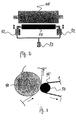
- Fig. 1 is a schematic of a production apparatus 10 embodying this invention.
- buff tapes are produced according to this invention by slitting a mother tape 20 longitudinally into a plurality of strips and by winding up these slit stripes.
- the mother tape 20 is basically of the same structure as the target buff tapes 25 to be produced, having a backing film 25b of a suitable material such as PET with a suitable thickness and coated with abrading particles such as aluminum oxide particles of a desired size such as 0.1-5.0 ⁇ m mixed in a urethane binder and dried to form a polishing layer 25a, different from the target buff tapes to be produced essentially in that it is much wider.
- the mother tape 20 is typically produced and provided in the form of a roll, or a web 22, typically having a width of 100mm to 1000mm and a length of 100m to 1000m, and is mounted to a feed roller 23, from which it is unwound and fed to a slitting device 30.
- the slitting device 30 may be of a conventionally known kind, for example, comprising a male knife 34 and a female knife 32 which engage with respect to each other and between which the mother tape 20 unwound from the web 22 is fed, the peripheral speed of the male knife 34 being 1.01-1.20 times greater than that of the female knife 32, for example, such that the mother tape 20 fed in between is slit thereby into a plurality of buff tapes 25 each with a specified width, say, in a typical range of 0.25 to 1.5 inches.
- the buff tapes 25, into which the mother tape 20 is thus slit longitudinally by means of the slitting device 30, are individually wound up around take-up rollers 28. Although two separate rollers 28 are shown in Fig. 1 for clearly showing that a plurality of buffer tapes 25 are individually being produced, the produced plurality of buff tapes 25 may be adapted to be wound up around a single roller to be taken up.
- a guide roller 40 with a polished steel surface is provided between the slitting device 30 and the take-up rollers 28 for guiding the slit buff tapes 25 from the slitting device 30 to the take-up rollers 28 by contacting the surface of the tapes coated with the particles.
- An AC motor 43 with a controller is provided for driving the slitting device 30, the guide roller 40 and the take-up roller 28 through interconnecting means such as a series of gears, brakes and timing belts (not shown), corresponding to the feed speed of the mother tape 20 to the slitting device 30.
- interconnecting means such as a series of gears, brakes and timing belts (not shown), corresponding to the feed speed of the mother tape 20 to the slitting device 30.
- Such a mechanism for controlling the feed speed is well known and is not intended to limit the scope of the invention.
- a compression roller 50 having a compressible peripheral surface with hardness of Shore A 50-70 Durometers is provided proximally to the portion of the surface of the guide roller 40 where the buff tapes 25 are in contact.
- a mechanism such as comprising pneumatic cylinders 52 along with a compressed air supply valve 53, is provided for moving the compression roller 50 towards the guide roller 40 such that a specified pressure may be applied as shown in Fig. 3, and also away from the guide roller 40 to a retracted position as shown in Fig. 1.
- a wiping tape 45 of a material such as a clean-room approved wiping cloth of polyester or nylon commonly used as a consumable product for direct or indirect contact use with a hard disk substrate surface is unwound from a supply roller 46, threaded around the compression roller 50 where it contacts the guide roller 40 and rewound by a take-up roller 47 such that, as the compression roller 50 is moved towards the guiding roller by the operation of the pneumatic cylinders 52 serving as its moving mechanism, the wiping tape 45 contacts the buff tapes 25 on the side of their backing film 25b.
- the wiping tape 45 is pressed onto the buff tapes 25 between the guide roller 40 and the compression roller 50 on the downstream side of the slitting device 30.
- the wiping tape 45 contacts the buff tapes 25 across the entire width and from the side of the backing film 25b because experiments have shown that the loose particles to be removed according to this invention are mostly attracted to the PET material of the backing film 25b due to the electrostatic charge of the buff tapes 25.
- the wiping tape 45 is advanced over the contacting surface of the compression roller 50 in the direction opposite to the motion of the buff tapes 25 by being unwound from the supply roller 46 and rewound around the take-up roller 47 at a specified supply rate.
- This supply rate is optimally determined according to other operational conditions such as the feed speed of the mother tape 20 and the compressive pressure between the compression.
- the feed speed of the mother tape 20 should be greater than 10m/min from the point of view of the minimally acceptable productivity and should preferably be less than 30m/min from the point of view of the minimally acceptable winding quality for buff tapes 25 with a width of 1.375 inches.
- Table 1 shows some representative examples of preferred combination of the supply rate of the wiping tape 45 and the compressive pressure between the guide roller 40 and the compression roller 50 in the case of a compression roller with surface hardness of Shore A 50-70 Durometers for collecting debris particles of size of 0.3 to 5.0 ⁇ m on a 1 mil-PET backing film.
- Table 1 Feed speed of mother tape Supply rate of wiping tape Compressive pressure between guide roller and compression roller (kg/cm 2 ) 10 m/min 15 mm/min 2 kg/cm 2 15 m/min 22.5 mm/min 1.75 kg/cm 2 20 m/min 30 mm/min 1.5 kg/cm 2 25 m/min 37.5 mm/min 1.25 kg/cm 2 30 m/min 45 mm/min 1 kg/cm 2
Landscapes
- Engineering & Computer Science (AREA)
- Mechanical Engineering (AREA)
- Life Sciences & Earth Sciences (AREA)
- Forests & Forestry (AREA)
- Manufacturing Of Magnetic Record Carriers (AREA)
- Finish Polishing, Edge Sharpening, And Grinding By Specific Grinding Devices (AREA)
- Details Of Cutting Devices (AREA)
Applications Claiming Priority (1)
| Application Number | Priority Date | Filing Date | Title |
|---|---|---|---|
| US11/190,669 US20070023560A1 (en) | 2005-07-26 | 2005-07-26 | Apparatus for and method of producing buff tapes |
Publications (3)
| Publication Number | Publication Date |
|---|---|
| EP1747850A2 true EP1747850A2 (de) | 2007-01-31 |
| EP1747850A3 EP1747850A3 (de) | 2007-08-08 |
| EP1747850B1 EP1747850B1 (de) | 2009-03-25 |
Family
ID=37192386
Family Applications (1)
| Application Number | Title | Priority Date | Filing Date |
|---|---|---|---|
| EP06253873A Not-in-force EP1747850B1 (de) | 2005-07-26 | 2006-07-24 | Vorrichtung und Verfahren zur Herstellung von Schwabbelbänder |
Country Status (5)
| Country | Link |
|---|---|
| US (1) | US20070023560A1 (de) |
| EP (1) | EP1747850B1 (de) |
| JP (1) | JP2007050503A (de) |
| AT (1) | ATE426486T1 (de) |
| DE (1) | DE602006005866D1 (de) |
Cited By (1)
| Publication number | Priority date | Publication date | Assignee | Title |
|---|---|---|---|---|
| CN119750296A (zh) * | 2025-03-10 | 2025-04-04 | 四川省科学城久信科技有限公司 | 薄膜电容器极箔用自动化波浪分切修边装置 |
Families Citing this family (3)
| Publication number | Priority date | Publication date | Assignee | Title |
|---|---|---|---|---|
| JP4625517B2 (ja) | 2008-10-27 | 2011-02-02 | 富士フイルム株式会社 | 3次元表示装置および方法並びにプログラム |
| JP5967383B2 (ja) * | 2014-03-18 | 2016-08-10 | コニカミノルタ株式会社 | 後処理装置および画像形成システム |
| CN114405936A (zh) * | 2021-12-01 | 2022-04-29 | 西安泰金工业电化学技术有限公司 | 一种用于超薄铜箔表面的除尘装置 |
Citations (2)
| Publication number | Priority date | Publication date | Assignee | Title |
|---|---|---|---|---|
| JPS6347069A (ja) | 1986-08-08 | 1988-02-27 | Fuji Photo Film Co Ltd | 研磨テ−プの製造方法 |
| JPS63214911A (ja) | 1987-03-03 | 1988-09-07 | Fuji Photo Film Co Ltd | 磁気テ−プクリ−ニング装置 |
Family Cites Families (17)
| Publication number | Priority date | Publication date | Assignee | Title |
|---|---|---|---|---|
| JP3218617B2 (ja) * | 1990-07-02 | 2001-10-15 | ソニー株式会社 | カレンダーロールクリーニング装置 |
| JPH06773A (ja) * | 1992-06-22 | 1994-01-11 | Fuji Photo Film Co Ltd | 研磨テープの製造方法 |
| US5474248A (en) * | 1993-08-16 | 1995-12-12 | Product Search, Inc. | Slitter/rewinder machine |
| US5611826A (en) * | 1994-03-01 | 1997-03-18 | Fuji Photo Film Co., Ltd. | Abrasive tape |
| FR2722127B1 (fr) * | 1994-07-06 | 1996-08-14 | Kodak Pathe | Procede et dispositif pour le decoupage de produits photographiques en bandes |
| JPH0985631A (ja) * | 1995-09-28 | 1997-03-31 | Fuji Photo Film Co Ltd | 研磨体 |
| US5991954A (en) * | 1996-02-05 | 1999-11-30 | Fuji Photo Film Co., Ltd. | Apparatus for cleaning photo film |
| US5930857A (en) * | 1997-10-14 | 1999-08-03 | Eastman Kodak Company | Apparatus for cleaning a surface of a moving web |
| US6036787A (en) * | 1998-07-13 | 2000-03-14 | Dek Printing Machines, Ltd. | Stencil cleaning apparatus |
| JP3640291B2 (ja) * | 1998-12-07 | 2005-04-20 | 富士写真フイルム株式会社 | 磁気記録媒体の製造方法及びその製造装置 |
| FI105463B (fi) * | 1999-01-22 | 2000-08-31 | Valmet Corp | Menetelmä ja laite paperirainan rullauksessa |
| US6378154B1 (en) * | 1999-11-18 | 2002-04-30 | Seratek, Llc | Web cleaning system |
| JP3728406B2 (ja) * | 2000-06-15 | 2005-12-21 | シャープ株式会社 | 基板洗浄装置 |
| US6505372B1 (en) * | 2001-02-27 | 2003-01-14 | Amphenol Corporation | Wire cleaning apparatus and method |
| ITBG20020015A1 (it) * | 2002-04-23 | 2003-10-23 | Tgc Srl | Apparato per la preparazione e/o la rigenerazione di bobine detergenti in tessuto per la pulizia di cilindri di stampa o di equivalente prec |
| JP2005339593A (ja) * | 2004-05-24 | 2005-12-08 | Fuji Photo Film Co Ltd | 磁気テープおよびその製造方法 |
| US20060153977A1 (en) * | 2005-01-12 | 2006-07-13 | Fuji Photo Film Co., Ltd. | Magnetic tape, and manufacturing method and winding apparatus therefor |
-
2005
- 2005-07-26 US US11/190,669 patent/US20070023560A1/en not_active Abandoned
-
2006
- 2006-07-24 EP EP06253873A patent/EP1747850B1/de not_active Not-in-force
- 2006-07-24 AT AT06253873T patent/ATE426486T1/de not_active IP Right Cessation
- 2006-07-24 DE DE602006005866T patent/DE602006005866D1/de not_active Expired - Fee Related
- 2006-07-26 JP JP2006202868A patent/JP2007050503A/ja active Pending
Patent Citations (2)
| Publication number | Priority date | Publication date | Assignee | Title |
|---|---|---|---|---|
| JPS6347069A (ja) | 1986-08-08 | 1988-02-27 | Fuji Photo Film Co Ltd | 研磨テ−プの製造方法 |
| JPS63214911A (ja) | 1987-03-03 | 1988-09-07 | Fuji Photo Film Co Ltd | 磁気テ−プクリ−ニング装置 |
Cited By (1)
| Publication number | Priority date | Publication date | Assignee | Title |
|---|---|---|---|---|
| CN119750296A (zh) * | 2025-03-10 | 2025-04-04 | 四川省科学城久信科技有限公司 | 薄膜电容器极箔用自动化波浪分切修边装置 |
Also Published As
| Publication number | Publication date |
|---|---|
| EP1747850A3 (de) | 2007-08-08 |
| EP1747850B1 (de) | 2009-03-25 |
| DE602006005866D1 (de) | 2009-05-07 |
| JP2007050503A (ja) | 2007-03-01 |
| ATE426486T1 (de) | 2009-04-15 |
| US20070023560A1 (en) | 2007-02-01 |
Similar Documents
| Publication | Publication Date | Title |
|---|---|---|
| KR101569798B1 (ko) | 이차전지의 전극 노칭장치 | |
| JPS59156507A (ja) | 圧延ロ−ルの研削装置 | |
| KR100840120B1 (ko) | 슬리팅 절단면 버어처리 및 보호막 형성을 위한연속처리방법과 연속처리장치 | |
| EP1747850B1 (de) | Vorrichtung und Verfahren zur Herstellung von Schwabbelbänder | |
| CN101745858A (zh) | 平板研磨机 | |
| US5071083A (en) | Touch roller for plastic polymer film manufacturing apparatus | |
| DE69319255T2 (de) | Rollenreinigungsvorrichtung einer streckrichtmaschine | |
| CN114074854B (zh) | 一种具有除去液态废物功能的服饰商标激光卷料打标机的使用方法 | |
| JP3025125B2 (ja) | 打抜剥離方法および打抜剥離装置 | |
| CN215965602U (zh) | 一种带刮铣及除尘的精整装置 | |
| JP5056527B2 (ja) | 粉末圧延装置 | |
| JPH08243907A (ja) | ヘアライン仕上げ金属帯の製造方法および装置 | |
| DE29706768U1 (de) | Vorrichtung zur Bearbeitung von Magnetbändern | |
| CN223339677U (zh) | 一种自动分切式流延机 | |
| US6811472B2 (en) | Inline lapping of magnetic tape | |
| CN218370820U (zh) | 一种膜料收放设备 | |
| JP4857762B2 (ja) | 金属帯の表面欠陥防止方法および表面欠陥防止設備 | |
| KR200332891Y1 (ko) | 네일파일 제조용 합지장치 | |
| JPH06269753A (ja) | スリッター微粉除去装置 | |
| CN116140926B (zh) | 一种变压器铁芯硅钢片的纵剪系统及纵剪方法 | |
| CN217702919U (zh) | 一种金属卷带高效双面砂磨装置 | |
| JP4396329B2 (ja) | 帯状物接続装置 | |
| JPH04148742A (ja) | シート搬送装置 | |
| JP4274638B2 (ja) | 金属帯板のバリ取り方法及びその装置 | |
| SU1602702A1 (ru) | Способ ленточного шлифовани тел вращени |
Legal Events
| Date | Code | Title | Description |
|---|---|---|---|
| PUAI | Public reference made under article 153(3) epc to a published international application that has entered the european phase |
Free format text: ORIGINAL CODE: 0009012 |
|
| AK | Designated contracting states |
Kind code of ref document: A2 Designated state(s): AT BE BG CH CY CZ DE DK EE ES FI FR GB GR HU IE IS IT LI LT LU LV MC NL PL PT RO SE SI SK TR |
|
| AX | Request for extension of the european patent |
Extension state: AL BA HR MK YU |
|
| RIN1 | Information on inventor provided before grant (corrected) |
Inventor name: TIMBANG, ALVIN Inventor name: KODAKA, ICHIRO Inventor name: VAN BANG, VUONG |
|
| PUAL | Search report despatched |
Free format text: ORIGINAL CODE: 0009013 |
|
| AK | Designated contracting states |
Kind code of ref document: A3 Designated state(s): AT BE BG CH CY CZ DE DK EE ES FI FR GB GR HU IE IS IT LI LT LU LV MC NL PL PT RO SE SI SK TR |
|
| AX | Request for extension of the european patent |
Extension state: AL BA HR MK YU |
|
| RIN1 | Information on inventor provided before grant (corrected) |
Inventor name: VAN BANG, VUONGMIPOX INTERNATIONAL CORP Inventor name: KODAKA, ICHIRO Inventor name: TIMBANG, ALVIN |
|
| 17P | Request for examination filed |
Effective date: 20080111 |
|
| 17Q | First examination report despatched |
Effective date: 20080311 |
|
| AKX | Designation fees paid |
Designated state(s): AT BE BG CH CY CZ DE DK EE ES FI FR GB GR HU IE IS IT LI LT LU LV MC NL PL PT RO SE SI SK TR |
|
| GRAP | Despatch of communication of intention to grant a patent |
Free format text: ORIGINAL CODE: EPIDOSNIGR1 |
|
| GRAS | Grant fee paid |
Free format text: ORIGINAL CODE: EPIDOSNIGR3 |
|
| GRAA | (expected) grant |
Free format text: ORIGINAL CODE: 0009210 |
|
| AK | Designated contracting states |
Kind code of ref document: B1 Designated state(s): AT BE BG CH CY CZ DE DK EE ES FI FR GB GR HU IE IS IT LI LT LU LV MC NL PL PT RO SE SI SK TR |
|
| REG | Reference to a national code |
Ref country code: GB Ref legal event code: FG4D |
|
| REG | Reference to a national code |
Ref country code: CH Ref legal event code: EP |
|
| REG | Reference to a national code |
Ref country code: IE Ref legal event code: FG4D |
|
| REF | Corresponds to: |
Ref document number: 602006005866 Country of ref document: DE Date of ref document: 20090507 Kind code of ref document: P |
|
| PG25 | Lapsed in a contracting state [announced via postgrant information from national office to epo] |
Ref country code: FI Free format text: LAPSE BECAUSE OF FAILURE TO SUBMIT A TRANSLATION OF THE DESCRIPTION OR TO PAY THE FEE WITHIN THE PRESCRIBED TIME-LIMIT Effective date: 20090325 Ref country code: LT Free format text: LAPSE BECAUSE OF FAILURE TO SUBMIT A TRANSLATION OF THE DESCRIPTION OR TO PAY THE FEE WITHIN THE PRESCRIBED TIME-LIMIT Effective date: 20090325 Ref country code: SI Free format text: LAPSE BECAUSE OF FAILURE TO SUBMIT A TRANSLATION OF THE DESCRIPTION OR TO PAY THE FEE WITHIN THE PRESCRIBED TIME-LIMIT Effective date: 20090325 |
|
| PG25 | Lapsed in a contracting state [announced via postgrant information from national office to epo] |
Ref country code: LV Free format text: LAPSE BECAUSE OF FAILURE TO SUBMIT A TRANSLATION OF THE DESCRIPTION OR TO PAY THE FEE WITHIN THE PRESCRIBED TIME-LIMIT Effective date: 20090325 Ref country code: SE Free format text: LAPSE BECAUSE OF FAILURE TO SUBMIT A TRANSLATION OF THE DESCRIPTION OR TO PAY THE FEE WITHIN THE PRESCRIBED TIME-LIMIT Effective date: 20090625 Ref country code: PL Free format text: LAPSE BECAUSE OF FAILURE TO SUBMIT A TRANSLATION OF THE DESCRIPTION OR TO PAY THE FEE WITHIN THE PRESCRIBED TIME-LIMIT Effective date: 20090325 Ref country code: AT Free format text: LAPSE BECAUSE OF FAILURE TO SUBMIT A TRANSLATION OF THE DESCRIPTION OR TO PAY THE FEE WITHIN THE PRESCRIBED TIME-LIMIT Effective date: 20090325 |
|
| NLV1 | Nl: lapsed or annulled due to failure to fulfill the requirements of art. 29p and 29m of the patents act | ||
| PG25 | Lapsed in a contracting state [announced via postgrant information from national office to epo] |
Ref country code: BE Free format text: LAPSE BECAUSE OF FAILURE TO SUBMIT A TRANSLATION OF THE DESCRIPTION OR TO PAY THE FEE WITHIN THE PRESCRIBED TIME-LIMIT Effective date: 20090325 |
|
| PG25 | Lapsed in a contracting state [announced via postgrant information from national office to epo] |
Ref country code: CZ Free format text: LAPSE BECAUSE OF FAILURE TO SUBMIT A TRANSLATION OF THE DESCRIPTION OR TO PAY THE FEE WITHIN THE PRESCRIBED TIME-LIMIT Effective date: 20090325 Ref country code: PT Free format text: LAPSE BECAUSE OF FAILURE TO SUBMIT A TRANSLATION OF THE DESCRIPTION OR TO PAY THE FEE WITHIN THE PRESCRIBED TIME-LIMIT Effective date: 20090901 Ref country code: ES Free format text: LAPSE BECAUSE OF FAILURE TO SUBMIT A TRANSLATION OF THE DESCRIPTION OR TO PAY THE FEE WITHIN THE PRESCRIBED TIME-LIMIT Effective date: 20090706 Ref country code: EE Free format text: LAPSE BECAUSE OF FAILURE TO SUBMIT A TRANSLATION OF THE DESCRIPTION OR TO PAY THE FEE WITHIN THE PRESCRIBED TIME-LIMIT Effective date: 20090325 |
|
| PG25 | Lapsed in a contracting state [announced via postgrant information from national office to epo] |
Ref country code: RO Free format text: LAPSE BECAUSE OF FAILURE TO SUBMIT A TRANSLATION OF THE DESCRIPTION OR TO PAY THE FEE WITHIN THE PRESCRIBED TIME-LIMIT Effective date: 20090325 Ref country code: SK Free format text: LAPSE BECAUSE OF FAILURE TO SUBMIT A TRANSLATION OF THE DESCRIPTION OR TO PAY THE FEE WITHIN THE PRESCRIBED TIME-LIMIT Effective date: 20090325 Ref country code: IS Free format text: LAPSE BECAUSE OF FAILURE TO SUBMIT A TRANSLATION OF THE DESCRIPTION OR TO PAY THE FEE WITHIN THE PRESCRIBED TIME-LIMIT Effective date: 20090725 Ref country code: NL Free format text: LAPSE BECAUSE OF FAILURE TO SUBMIT A TRANSLATION OF THE DESCRIPTION OR TO PAY THE FEE WITHIN THE PRESCRIBED TIME-LIMIT Effective date: 20090325 |
|
| PG25 | Lapsed in a contracting state [announced via postgrant information from national office to epo] |
Ref country code: BG Free format text: LAPSE BECAUSE OF FAILURE TO SUBMIT A TRANSLATION OF THE DESCRIPTION OR TO PAY THE FEE WITHIN THE PRESCRIBED TIME-LIMIT Effective date: 20090625 Ref country code: DK Free format text: LAPSE BECAUSE OF FAILURE TO SUBMIT A TRANSLATION OF THE DESCRIPTION OR TO PAY THE FEE WITHIN THE PRESCRIBED TIME-LIMIT Effective date: 20090325 |
|
| PLBE | No opposition filed within time limit |
Free format text: ORIGINAL CODE: 0009261 |
|
| STAA | Information on the status of an ep patent application or granted ep patent |
Free format text: STATUS: NO OPPOSITION FILED WITHIN TIME LIMIT |
|
| PG25 | Lapsed in a contracting state [announced via postgrant information from national office to epo] |
Ref country code: MC Free format text: LAPSE BECAUSE OF NON-PAYMENT OF DUE FEES Effective date: 20090731 |
|
| 26N | No opposition filed |
Effective date: 20091229 |
|
| PG25 | Lapsed in a contracting state [announced via postgrant information from national office to epo] |
Ref country code: DE Free format text: LAPSE BECAUSE OF NON-PAYMENT OF DUE FEES Effective date: 20100202 |
|
| PG25 | Lapsed in a contracting state [announced via postgrant information from national office to epo] |
Ref country code: IE Free format text: LAPSE BECAUSE OF NON-PAYMENT OF DUE FEES Effective date: 20090724 |
|
| PG25 | Lapsed in a contracting state [announced via postgrant information from national office to epo] |
Ref country code: GR Free format text: LAPSE BECAUSE OF FAILURE TO SUBMIT A TRANSLATION OF THE DESCRIPTION OR TO PAY THE FEE WITHIN THE PRESCRIBED TIME-LIMIT Effective date: 20090626 |
|
| PGFP | Annual fee paid to national office [announced via postgrant information from national office to epo] |
Ref country code: FR Payment date: 20100805 Year of fee payment: 5 |
|
| REG | Reference to a national code |
Ref country code: CH Ref legal event code: PL |
|
| GBPC | Gb: european patent ceased through non-payment of renewal fee |
Effective date: 20100724 |
|
| PG25 | Lapsed in a contracting state [announced via postgrant information from national office to epo] |
Ref country code: IT Free format text: LAPSE BECAUSE OF FAILURE TO SUBMIT A TRANSLATION OF THE DESCRIPTION OR TO PAY THE FEE WITHIN THE PRESCRIBED TIME-LIMIT Effective date: 20090325 |
|
| PG25 | Lapsed in a contracting state [announced via postgrant information from national office to epo] |
Ref country code: CH Free format text: LAPSE BECAUSE OF NON-PAYMENT OF DUE FEES Effective date: 20100731 Ref country code: LI Free format text: LAPSE BECAUSE OF NON-PAYMENT OF DUE FEES Effective date: 20100731 Ref country code: LU Free format text: LAPSE BECAUSE OF NON-PAYMENT OF DUE FEES Effective date: 20090724 |
|
| PG25 | Lapsed in a contracting state [announced via postgrant information from national office to epo] |
Ref country code: HU Free format text: LAPSE BECAUSE OF FAILURE TO SUBMIT A TRANSLATION OF THE DESCRIPTION OR TO PAY THE FEE WITHIN THE PRESCRIBED TIME-LIMIT Effective date: 20090926 |
|
| PG25 | Lapsed in a contracting state [announced via postgrant information from national office to epo] |
Ref country code: GB Free format text: LAPSE BECAUSE OF NON-PAYMENT OF DUE FEES Effective date: 20100724 |
|
| PG25 | Lapsed in a contracting state [announced via postgrant information from national office to epo] |
Ref country code: TR Free format text: LAPSE BECAUSE OF FAILURE TO SUBMIT A TRANSLATION OF THE DESCRIPTION OR TO PAY THE FEE WITHIN THE PRESCRIBED TIME-LIMIT Effective date: 20090325 |
|
| PG25 | Lapsed in a contracting state [announced via postgrant information from national office to epo] |
Ref country code: CY Free format text: LAPSE BECAUSE OF FAILURE TO SUBMIT A TRANSLATION OF THE DESCRIPTION OR TO PAY THE FEE WITHIN THE PRESCRIBED TIME-LIMIT Effective date: 20090325 |
|
| REG | Reference to a national code |
Ref country code: FR Ref legal event code: ST Effective date: 20120330 |
|
| PG25 | Lapsed in a contracting state [announced via postgrant information from national office to epo] |
Ref country code: FR Free format text: LAPSE BECAUSE OF NON-PAYMENT OF DUE FEES Effective date: 20110801 |