EP1749706A2 - Lenkrad mit AIrbag-Vorrichtung - Google Patents
Lenkrad mit AIrbag-Vorrichtung Download PDFInfo
- Publication number
- EP1749706A2 EP1749706A2 EP06014156A EP06014156A EP1749706A2 EP 1749706 A2 EP1749706 A2 EP 1749706A2 EP 06014156 A EP06014156 A EP 06014156A EP 06014156 A EP06014156 A EP 06014156A EP 1749706 A2 EP1749706 A2 EP 1749706A2
- Authority
- EP
- European Patent Office
- Prior art keywords
- airbag apparatus
- steering wheel
- module cover
- spoke
- airbag
- Prior art date
- Legal status (The legal status is an assumption and is not a legal conclusion. Google has not performed a legal analysis and makes no representation as to the accuracy of the status listed.)
- Granted
Links
- 238000004519 manufacturing process Methods 0.000 abstract description 4
- 230000037431 insertion Effects 0.000 description 6
- 238000003780 insertion Methods 0.000 description 6
- 230000000994 depressogenic effect Effects 0.000 description 4
- 238000007664 blowing Methods 0.000 description 3
- 230000000717 retained effect Effects 0.000 description 2
- 230000000452 restraining effect Effects 0.000 description 1
- 125000006850 spacer group Chemical group 0.000 description 1
- 229920003002 synthetic resin Polymers 0.000 description 1
- 239000000057 synthetic resin Substances 0.000 description 1
Images

Classifications
-
- B—PERFORMING OPERATIONS; TRANSPORTING
- B60—VEHICLES IN GENERAL
- B60R—VEHICLES, VEHICLE FITTINGS, OR VEHICLE PARTS, NOT OTHERWISE PROVIDED FOR
- B60R21/00—Arrangements or fittings on vehicles for protecting or preventing injuries to occupants or pedestrians in case of accidents or other traffic risks
- B60R21/02—Occupant safety arrangements or fittings, e.g. crash pads
- B60R21/16—Inflatable occupant restraints or confinements designed to inflate upon impact or impending impact, e.g. air bags
- B60R21/20—Arrangements for storing inflatable members in their non-use or deflated condition; Arrangement or mounting of air bag modules or components
- B60R21/203—Arrangements for storing inflatable members in their non-use or deflated condition; Arrangement or mounting of air bag modules or components in steering wheels or steering columns
- B60R21/2035—Arrangements for storing inflatable members in their non-use or deflated condition; Arrangement or mounting of air bag modules or components in steering wheels or steering columns using modules containing inflator, bag and cover attachable to the steering wheel as a complete sub-unit
- B60R21/2037—Arrangements for storing inflatable members in their non-use or deflated condition; Arrangement or mounting of air bag modules or components in steering wheels or steering columns using modules containing inflator, bag and cover attachable to the steering wheel as a complete sub-unit the module or a major component thereof being yieldably mounted, e.g. for actuating the horn switch or for protecting the driver in a non-deployment situation
-
- B—PERFORMING OPERATIONS; TRANSPORTING
- B60—VEHICLES IN GENERAL
- B60R—VEHICLES, VEHICLE FITTINGS, OR VEHICLE PARTS, NOT OTHERWISE PROVIDED FOR
- B60R21/00—Arrangements or fittings on vehicles for protecting or preventing injuries to occupants or pedestrians in case of accidents or other traffic risks
- B60R21/02—Occupant safety arrangements or fittings, e.g. crash pads
- B60R21/16—Inflatable occupant restraints or confinements designed to inflate upon impact or impending impact, e.g. air bags
- B60R21/20—Arrangements for storing inflatable members in their non-use or deflated condition; Arrangement or mounting of air bag modules or components
- B60R21/215—Arrangements for storing inflatable members in their non-use or deflated condition; Arrangement or mounting of air bag modules or components characterised by the covers for the inflatable member
- B60R21/2165—Arrangements for storing inflatable members in their non-use or deflated condition; Arrangement or mounting of air bag modules or components characterised by the covers for the inflatable member characterised by a tear line for defining a deployment opening
- B60R21/21656—Steering wheel covers or similar cup-shaped covers
Definitions
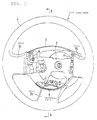
- a steering wheel with an airbag apparatus according to the present invention (Claim 1) is characterized in that the airbag apparatus is disposed substantially in the center of the steering wheel having spokes; the outer periphery of a module cover of the airbag apparatus covers the spokes; and a concealer for concealing the interior of the airbag apparatus is provided at the gap between the outer periphery of the module cover and the surface of the spoke adjacent to an occupant, wherein the concealer is constructed of a projecting strip provided at the surface of the spoke adjacent to the occupant and the outer rim of the module cover disposed close to the side of the projecting strip adjacent to the outer periphery of the steering wheel.
- the steering wheel with an airbag according to the invention has a concealer constructed of a projecting strip disposed on the occupant side of the spokes and the outer rim of the module cover disposed close to the side of the projecting strip adjacent to the outer periphery of the module cover.
- the concealer reliably prevents the interior of the airbag apparatus from being viewed. This structure eliminates the need for mounting a separate blind cover to the module cover, facilitating manufacture, and providing good appearance.
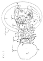
- a base plate 6 that configures a horn switch is disposed in front of the steering base 2.
- the airbag apparatus 10 is joined to the base plate 6 with a guide shaft 41. Between the base plate 6 and the airbag apparatus 10, a coil spring 40 is disposed which biases the airbag apparatus 10 away from the base plate 6.
- the joint structure of the airbag apparatus 10 to the steering wheel 1 and the structure of the horn switch will be specifically described hereinlater.
- the retainer 11 has a main plate 11a disposed in front of the steering base 2.
- the main plate 11a has an opening 11b for the inflator 14 to be inserted.
- insertion holes (the reference numerals are omitted) for stud bolts 12a are provided which stand from the airbag mounting ring 12.
- the distal end of the inflator 14 is inserted from the back into the inflator opening 11b, and a flange 14a provided around the side periphery is placed on the periphery of the inflator opening 11b.
- the stud bolts 12a are also inserted into bolt insertion holes (the reference numeral is omitted) of the flange 14a. Nuts (not shown) are tightened to the stud bolts 12a, thereby fixing the airbag 13, the airbag mounting ring 12, and the inflator 14 to the main plate 11a.
- a horn-switch-contact retaining piece 16 stands erect from each of the right and left opposite rims and the lower rim of the main plate 11a of the retainer 11.
- the contact retaining pieces 16 project from the main plate 11a toward the occupant, from the ends of which extensions 16a extend to the side of the airbag apparatus 10 (in the direction substantially orthogonal to the front back direction of the airbag apparatus 10).
- the base plate 6 that is joined to the retainer 11 in advance is superposed on the front surface of the steering base 2, and a leg-like piece 6a is fixed to the steering base 2 with bolts or rivets (not shown).
Landscapes
- Engineering & Computer Science (AREA)
- Mechanical Engineering (AREA)
- Air Bags (AREA)
- Steering Controls (AREA)
Applications Claiming Priority (1)
| Application Number | Priority Date | Filing Date | Title |
|---|---|---|---|
| JP2005228355A JP4661442B2 (ja) | 2005-08-05 | 2005-08-05 | エアバッグ装置付きステアリングホイール |
Publications (3)
| Publication Number | Publication Date |
|---|---|
| EP1749706A2 true EP1749706A2 (de) | 2007-02-07 |
| EP1749706A3 EP1749706A3 (de) | 2008-03-19 |
| EP1749706B1 EP1749706B1 (de) | 2010-09-08 |
Family
ID=36932689
Family Applications (1)
| Application Number | Title | Priority Date | Filing Date |
|---|---|---|---|
| EP06014156A Not-in-force EP1749706B1 (de) | 2005-08-05 | 2006-07-07 | Lenkrad mit AIrbag-Vorrichtung |
Country Status (5)
| Country | Link |
|---|---|
| US (1) | US7467808B2 (de) |
| EP (1) | EP1749706B1 (de) |
| JP (1) | JP4661442B2 (de) |
| CN (1) | CN1907763A (de) |
| DE (1) | DE602006016693D1 (de) |
Families Citing this family (3)
| Publication number | Priority date | Publication date | Assignee | Title |
|---|---|---|---|---|
| DE102011078835A1 (de) * | 2011-07-07 | 2013-01-10 | TAKATA Aktiengesellschaft | Fahrzeuglenkrad, Gassackmodul für ein Fahrzeuglenkrad und Verfahren zur Montage eines Fahrzeuglenkrads an einer Lenkwelle |
| US9008999B2 (en) * | 2011-10-27 | 2015-04-14 | Toyota Motor Engineering & Manufacturing North America, Inc. | Steering wheel airbag position detector |
| US9073508B1 (en) | 2014-07-08 | 2015-07-07 | Ford Global Technologies, Llc | Driver airbag to steering wheel gap reduction |
Citations (1)
| Publication number | Priority date | Publication date | Assignee | Title |
|---|---|---|---|---|
| JP2000025548A (ja) | 1998-07-16 | 2000-01-25 | Tokai Rika Co Ltd | エアバッグ装置 |
Family Cites Families (20)
| Publication number | Priority date | Publication date | Assignee | Title |
|---|---|---|---|---|
| DE2052357A1 (de) * | 1970-10-24 | 1972-04-27 | Lenkradwerk Gustav Petri Ag, 8750 Aschaffenburg | Lenkrad mit eingebautem Luftkissen |
| JPS5119893B2 (de) * | 1971-12-08 | 1976-06-21 | ||
| JPS5146932B2 (de) * | 1972-02-29 | 1976-12-11 | ||
| JPH05116578A (ja) * | 1991-10-29 | 1993-05-14 | Nippon Plast Co Ltd | エアバツグ装置付きステアリングホイール |
| JPH05116582A (ja) * | 1991-10-29 | 1993-05-14 | Nippon Plast Co Ltd | エアバツグ装置付きステアリングホイール |
| JPH0592004U (ja) | 1992-03-12 | 1993-12-14 | センサー・テクノロジー株式会社 | エアバッグモジュール |
| JPH06312643A (ja) * | 1993-04-30 | 1994-11-08 | Tokai Rika Co Ltd | エアバッグ装置付きステアリング装置 |
| JPH07101340A (ja) | 1993-10-08 | 1995-04-18 | Toyoda Gosei Co Ltd | ステアリングホイールパッドの取付構造 |
| JPH09272391A (ja) | 1996-04-10 | 1997-10-21 | Tokai Rika Co Ltd | エアバッグ用カバー |
| US6478330B2 (en) * | 1996-08-06 | 2002-11-12 | Toyoda Gosei Co., Ltd. | Steering wheel |
| DE69725246T2 (de) * | 1996-08-06 | 2004-07-29 | Toyoda Gosei Co., Ltd., Haruhi | Lenkrad |
| US6161863A (en) * | 1996-08-06 | 2000-12-19 | Toyoda Gosei Co., Ltd. | Air bag device |
| JPH10273057A (ja) | 1997-03-31 | 1998-10-13 | Toyoda Gosei Co Ltd | ステアリングホイール |
| JPH11144555A (ja) | 1997-11-07 | 1999-05-28 | Tokai Rika Co Ltd | ステアリングホイール |
| IT244021Y1 (it) * | 1998-05-22 | 2002-03-07 | Breed Automotive Tech | Volante per autoveicolo provvisto di dispositivo di protezione acuscino d'aria con parti metalliche di ricopertura delle razze |
| DE29906377U1 (de) * | 1999-04-09 | 1999-06-17 | TRW Automotive Safety Systems GmbH & Co.KG, 63743 Aschaffenburg | Lenkrad mit Airbagmodul |
| JP2001233159A (ja) * | 2000-02-18 | 2001-08-28 | Tokai Rika Co Ltd | エアバッグ装置組付構造 |
| US6626458B2 (en) * | 2000-09-26 | 2003-09-30 | Toyoda Gosei Co., Ltd. | Steering wheel having airbag apparatus |
| JP3958012B2 (ja) | 2001-10-11 | 2007-08-15 | 芦森工業株式会社 | エアバッグ装置及びそのカバー |
| JP4227750B2 (ja) | 2002-01-31 | 2009-02-18 | オートリブ株式会社 | エアバッグ装置付きステアリングホイール |
-
2005
- 2005-08-05 JP JP2005228355A patent/JP4661442B2/ja not_active Expired - Fee Related
-
2006
- 2006-07-07 EP EP06014156A patent/EP1749706B1/de not_active Not-in-force
- 2006-07-07 DE DE602006016693T patent/DE602006016693D1/de active Active
- 2006-07-31 US US11/495,592 patent/US7467808B2/en not_active Expired - Fee Related
- 2006-08-07 CN CNA2006101101344A patent/CN1907763A/zh active Pending
Patent Citations (1)
| Publication number | Priority date | Publication date | Assignee | Title |
|---|---|---|---|---|
| JP2000025548A (ja) | 1998-07-16 | 2000-01-25 | Tokai Rika Co Ltd | エアバッグ装置 |
Also Published As
| Publication number | Publication date |
|---|---|
| US20070029766A1 (en) | 2007-02-08 |
| EP1749706A3 (de) | 2008-03-19 |
| EP1749706B1 (de) | 2010-09-08 |
| JP4661442B2 (ja) | 2011-03-30 |
| JP2007045170A (ja) | 2007-02-22 |
| DE602006016693D1 (de) | 2010-10-21 |
| US7467808B2 (en) | 2008-12-23 |
| CN1907763A (zh) | 2007-02-07 |
Similar Documents
| Publication | Publication Date | Title |
|---|---|---|
| US5085461A (en) | Air bag mount device for steering wheel including control switches | |
| US7708310B2 (en) | Steering column including an airbag apparatus | |
| US8465048B2 (en) | Airbag cover | |
| US20100127485A1 (en) | Knee airbag device and conecting method thereof | |
| JP2606466Y2 (ja) | エアバッグ装置 | |
| EP1749706A2 (de) | Lenkrad mit AIrbag-Vorrichtung | |
| JP2004168284A (ja) | エアバッグ装置 | |
| US8931799B2 (en) | Airbag device and steering wheel | |
| JP4674409B2 (ja) | エアバッグ装置 | |
| JPH1148895A (ja) | エアバッグ装置 | |
| JP5582848B2 (ja) | ハンドル | |
| JP2001191887A (ja) | 車両用エアバッグ装置 | |
| JP7544629B2 (ja) | 車両用内装部材及びハンドル | |
| JP2006218903A (ja) | エアバッグ装置付きステアリングホイール | |
| JP4158721B2 (ja) | エアバッグ装置 | |
| JP2001354095A (ja) | エアバッグ装置 | |
| KR200296780Y1 (ko) | 에어백 조립체 | |
| KR20090028099A (ko) | 차량의 에어백 모듈 | |
| JPH0710971Y2 (ja) | ガスバッグのカバー体 | |
| JP3020744U (ja) | エアバッグモジュール | |
| KR200280010Y1 (ko) | 에어백 조립체 | |
| JPH11105657A (ja) | エアバッグ装置一体型ステアリングホイール | |
| JP2002264759A (ja) | エアバッグ装置の取付構造 | |
| JPH08253155A (ja) | ステアリングホイール | |
| KR0152008B1 (ko) | 조향 휠 조립체 |
Legal Events
| Date | Code | Title | Description |
|---|---|---|---|
| PUAI | Public reference made under article 153(3) epc to a published international application that has entered the european phase |
Free format text: ORIGINAL CODE: 0009012 |
|
| AK | Designated contracting states |
Kind code of ref document: A2 Designated state(s): AT BE BG CH CY CZ DE DK EE ES FI FR GB GR HU IE IS IT LI LT LU LV MC NL PL PT RO SE SI SK TR |
|
| AX | Request for extension of the european patent |
Extension state: AL BA HR MK YU |
|
| PUAL | Search report despatched |
Free format text: ORIGINAL CODE: 0009013 |
|
| AK | Designated contracting states |
Kind code of ref document: A3 Designated state(s): AT BE BG CH CY CZ DE DK EE ES FI FR GB GR HU IE IS IT LI LT LU LV MC NL PL PT RO SE SI SK TR |
|
| AX | Request for extension of the european patent |
Extension state: AL BA HR MK YU |
|
| 17P | Request for examination filed |
Effective date: 20080812 |
|
| 17Q | First examination report despatched |
Effective date: 20080917 |
|
| AKX | Designation fees paid |
Designated state(s): DE FR GB SE |
|
| GRAP | Despatch of communication of intention to grant a patent |
Free format text: ORIGINAL CODE: EPIDOSNIGR1 |
|
| GRAS | Grant fee paid |
Free format text: ORIGINAL CODE: EPIDOSNIGR3 |
|
| GRAA | (expected) grant |
Free format text: ORIGINAL CODE: 0009210 |
|
| AK | Designated contracting states |
Kind code of ref document: B1 Designated state(s): DE FR GB SE |
|
| REG | Reference to a national code |
Ref country code: GB Ref legal event code: FG4D |
|
| REF | Corresponds to: |
Ref document number: 602006016693 Country of ref document: DE Date of ref document: 20101021 Kind code of ref document: P |
|
| PG25 | Lapsed in a contracting state [announced via postgrant information from national office to epo] |
Ref country code: SE Free format text: LAPSE BECAUSE OF FAILURE TO SUBMIT A TRANSLATION OF THE DESCRIPTION OR TO PAY THE FEE WITHIN THE PRESCRIBED TIME-LIMIT Effective date: 20100908 |
|
| PLBE | No opposition filed within time limit |
Free format text: ORIGINAL CODE: 0009261 |
|
| STAA | Information on the status of an ep patent application or granted ep patent |
Free format text: STATUS: NO OPPOSITION FILED WITHIN TIME LIMIT |
|
| 26N | No opposition filed |
Effective date: 20110609 |
|
| REG | Reference to a national code |
Ref country code: DE Ref legal event code: R097 Ref document number: 602006016693 Country of ref document: DE Effective date: 20110609 |
|
| REG | Reference to a national code |
Ref country code: FR Ref legal event code: ST Effective date: 20120330 |
|
| PG25 | Lapsed in a contracting state [announced via postgrant information from national office to epo] |
Ref country code: FR Free format text: LAPSE BECAUSE OF NON-PAYMENT OF DUE FEES Effective date: 20110801 |
|
| PGFP | Annual fee paid to national office [announced via postgrant information from national office to epo] |
Ref country code: DE Payment date: 20130703 Year of fee payment: 8 |
|
| PGFP | Annual fee paid to national office [announced via postgrant information from national office to epo] |
Ref country code: GB Payment date: 20130703 Year of fee payment: 8 |
|
| REG | Reference to a national code |
Ref country code: DE Ref legal event code: R119 Ref document number: 602006016693 Country of ref document: DE |
|
| GBPC | Gb: european patent ceased through non-payment of renewal fee |
Effective date: 20140707 |
|
| PG25 | Lapsed in a contracting state [announced via postgrant information from national office to epo] |
Ref country code: DE Free format text: LAPSE BECAUSE OF NON-PAYMENT OF DUE FEES Effective date: 20150203 |
|
| REG | Reference to a national code |
Ref country code: DE Ref legal event code: R119 Ref document number: 602006016693 Country of ref document: DE Effective date: 20150203 |
|
| PG25 | Lapsed in a contracting state [announced via postgrant information from national office to epo] |
Ref country code: GB Free format text: LAPSE BECAUSE OF NON-PAYMENT OF DUE FEES Effective date: 20140707 |