EP1749906A2 - Arrangement de rattachement pour une métier à filer à bout libre à rotor - Google Patents
Arrangement de rattachement pour une métier à filer à bout libre à rotor Download PDFInfo
- Publication number
- EP1749906A2 EP1749906A2 EP06012221A EP06012221A EP1749906A2 EP 1749906 A2 EP1749906 A2 EP 1749906A2 EP 06012221 A EP06012221 A EP 06012221A EP 06012221 A EP06012221 A EP 06012221A EP 1749906 A2 EP1749906 A2 EP 1749906A2
- Authority
- EP
- European Patent Office
- Prior art keywords
- thread
- spinning
- drive
- rotor
- open
- Prior art date
- Legal status (The legal status is an assumption and is not a legal conclusion. Google has not performed a legal analysis and makes no representation as to the accuracy of the status listed.)
- Granted
Links
Images


Classifications
-
- D—TEXTILES; PAPER
- D01—NATURAL OR MAN-MADE THREADS OR FIBRES; SPINNING
- D01H—SPINNING OR TWISTING
- D01H4/00—Open-end spinning machines or arrangements for imparting twist to independently moving fibres separated from slivers; Piecing arrangements therefor; Covering endless core threads with fibres by open-end spinning techniques
- D01H4/48—Piecing arrangements; Control therefor
- D01H4/50—Piecing arrangements; Control therefor for rotor spinning
Definitions
- the invention relates to an open-end rotor spinning machine according to the preamble of claim 1.
- Such open-end rotor spinning machines have, as known and for example in the DE 198 36 065 A1 described over a plurality of similar, in series juxtaposed jobs on which a preferably presented in a sliver can sliver is spun into a thread and then wound into a cross-wound bobbin.
- the individual jobs have for this purpose in each case a spinning device and a winding device, wherein both the working members of the spinning device and the working members of the winding device are usually acted upon by machine-length drive means.
- tangential belts for driving the spinning rotors and the sliver opening rollers as well as a machine-length drive shaft for loading the sliver take-up cylinders are arranged.
- the drive of the arranged in the field of winding devices coil drive roller also takes place via a machine-length drive shaft.
- a reciprocating yarn guide rod is present, which is acted upon by a machine end side arranged traversing gear and to which the thread guides are fixed.
- thread take-off devices are available whose driven take-off rollers are part of a continuous drive shaft.
- the jobs of such open-end rotor spinning machines are cared for by service units, for example, patrolling along the jobs and automatically intervene when at one of the jobs an accident, such as a thread break, has occurred.
- the service unit runs to the relevant work site, locks there and searches with a pivotally mounted, sauchristbeaufschlagbaren suction nozzle accumulated after a yarn breakage on the cheese thread.
- Such service units have, in addition to the suction nozzle on a number of other thread handling elements, which make it possible to spin the recorded by the suction nozzle thread after a corresponding preparation in the open-end rotor spinning of the relevant job to a revolving there with the spinning rotor fiber ring.
- the drive of the individual thread handling elements of the service unit, including the suction nozzle preferably takes place via an electric motor which drives a cam disk pack which is connected to the thread handling elements via special lever linkage.
- a disadvantage of these devices is that the piecing of a new thread to the circumferential in the rotor groove fiber ring is largely uncontrolled. That is, in these known devices, neither an exact tuning of the fiber feed into the spinning rotor nor an accurate timing of the thread take-off on the speed of the spinning rotor is given, which means that the piezos produced with these known devices meet today's quality standards in any way.
- An open-end spinning machine is known in which different individual drives are arranged in the area of the work stations.
- the jobs of this rotor spinning machine have, for example, an open-end rotor spinning device with a single-motor driven sliver feed cylinder, a single-motor driven thread take-off device and a single drive for the bobbin drive roller.
- the EP 1 283 288 A2 described an open-end rotor spinning machine whose jobs are designed so that they can resolve incidents, especially thread breaks, automatically.
- the largely self-sufficient workstations of this known open-end rotor spinning machine have, in addition to a spinning station's own suction nozzle, among others, individual drives for the bobbin drive roller and the thread withdrawal device.
- the work stations also each have a piecing auxiliary device arranged in the region of the open-end rotor spinning device in which the thread prepared by the suction nozzle is prepared for re-spinning.
- the present invention seeks to provide a cost-effective open-end rotor spinning machine, which is designed so that the jobs can be spun easily after a failure again, without the need for a special service unit is necessary, the quality The created piecing should meet today's high quality standards.
- the embodiment of an open-end rotor spinning machine described in claim 1 has the particular advantage that it is on the one hand inexpensive to implement and on the other hand enables the production of Anspinnern that meet today's high quality requirements.
- a stationary device in the region of the open-end rotor spinning device, which makes it possible in a simple way to exactly cut down a manually retrieved from the cheese package thread.
- the cut-to-length thread can then immediately be properly prepared for re-feeding into the open-end rotor spinning device by a manual thread preparation device, which the operator preferably carries with him. That is, the thread end is made largely swirl-free.
- the manual thread preparation has the advantage that the operator can visually check the result of his preparation and correct if necessary. In this way it can be ensured that only properly prepared yarn ends are fed back into the spinning device for re-spinning, which has a very positive effect on the quality of the piecing.
- control device of the job is so formed and connected to the thread take-off device that started with manual activation of the control immediately a feed of fibers into the spinning rotor and also time and length exactly the return of the cut thread end in the spinning rotor rotating at operating speed is initiated.
- the control device ensures an extremely precise feeding of the thread, that is, the prepared thread is properly returned to the spinning rotor and applied to the rotating there fiber ring.
- the spinning rotor is rotated either by a machine-tangential belt or by a single drive.
- the sliver-opening roller can be either as described in claim 6 via a machine-tangential belt or, as set forth in claim 7, driven by a single drive, which is preferably formed in such a case as a so-called external rotor drive.
- a drive means for lifting the cross-wound bobbin from the bobbin drive roller is provided.
- the drive device is included preferably designed as a thrust piston gear, which acts on the coil frame, in which the cross-wound bobbin is held and which can be controlled by a defined by a solenoid valve by the control device.
- the cross-wound bobbin can be selectively placed during the piecing process on the rotating bobbin drive roller and accelerated after re-spinning the thread quickly at least to a speed at which the peripheral speed of the cheese corresponds to the thread take-off speed.
- the pneumatic thread store also takes on the thread length, which is needed at the beginning of the piecing process in connection with the thread return.
- the creel also has a braking device by which the cross-wound bobbin can be fixed against rotation as needed. That is, after the manual retrieval of the thread prevents the braking device that in addition to the required in connection with the formation of the piecing thread length inadvertently further, the piecing process negatively influencing thread material is unwound from the cross-wound bobbin.
- FIG. 1 shows one half of a semiautomatic open-end rotor spinning machine 1 according to the invention.
- Such spinning machines have a plurality of jobs 2, which are each equipped with a spinning device 3 and a winding device 33.
- the sliver 34 presented in the spinning cans 28 is spun in each case into a thread 30, which is wound on the winding device 33 to form a cross-wound bobbin 22.
- the winding devices 33 have, as is known, in each case a coil frame 21 for rotatably supporting the sleeve of a cheese 22, a bobbin drive roller 23, a Fadenchangier observed 26 and a device 7 for lifting the cross-wound bobbin 22 of the bobbin drive roller 23.
- the device 7 is designed for example as a thrust piston, which is connected via a pneumatic line 24, in which a solenoid valve 17 is turned on, to a (not shown) overpressure source.
- a brake device 50 is arranged on the creel 21, by means of which a free rotation of the cross-wound bobbin 22 lifted off the bobbin drive roller 23 can be prevented, if necessary.
- the drive of the bobbin drive roller 23 takes place as a group drive. That is, there is provided a machine-length drive shaft to which the individual reel drive rollers 23 are fixed. In an alternative embodiment, however, a single motor drive of the bobbin drive roller 23 is possible. In such a case, the drive of the bobbin drive roller, a corresponding control line to the spinning station's own control device 9 is connected.
- the thread lifting device In the area of the winding device 33 can also be a, known per se, (not shown) thread lifting device to be installed.
- a thread lifting device prevents the thread during the piecing process can be unintentionally detected by the traversing Fadenchangier Anlagen 26. That is, the thread lifting device formed, for example, as a hinged plate holds the thread during the actual piecing initially at a distance above the reciprocating Fadenchangier issued 26th
- the spinning device 3 has a spinning rotor 4, a thread-band opening roller 12 and a sliver-picking cylinder 14.
- the spinning rotor 4 is mounted, for example, in a support disk bearing 5 and is driven by a machine-tangential belt 6.
- a sensor device 8 can also be provided, which is then connected to the control device 9 via a signal line 40.
- the sliver-opening roller 12 is preferably also acted upon by a machine-tangential belt 13, while the sliver-picking cylinder 14 is driven by a motor 15 single motor.
- the drive of the sliver feed cylinder 14, for example a stepper motor 15, is likewise connected to the control direction 9 via a control line 16.
- the work stations 2 each have a thread withdrawal device 18, the drive 19 is connected via a control line 20 to the control direction 9 in connection.
- a yarn storage device 37 When viewed in the direction of yarn travel, a yarn storage device 37, preferably a pneumatically actuable storage nozzle, is also provided behind the yarn withdrawal device 18.
- the storage nozzle 37 is connected via a pneumatic line 38 to a (not shown) vacuum source.
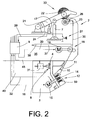
- a stationary device 10 is arranged, which permits a defined cutting to length of a thread manually retrieved from the cross-wound bobbin 22, the thread end of which can subsequently be treated by the operating personnel through the thread preparation device 25 shown in FIG.
- This thread preparation device 25 for the manual preparation of the thread consists essentially of a handle 36 and a thread treatment area 35 for processing the thread end.
- the control device 9 which drives the device 7 for lifting the cross-wound bobbin, the drive 16 of the thread withdrawal device 18 and the drive 15 of the sliver feed cylinder 14 controls, connected via a signal line 29 to a switching element 27. That is, the control device 9 can be manually activated via the switching element 27.
- the spinning rotor 4 is not supported in a support disk bearing 5, but in a, only schematically indicated magnetic bearing.
- the spinning rotor 4 is preferably acted upon by a single drive 31 in such a case.
- the spinning rotor drive 31 is connected via a control line 45 to the control device 9 in connection.
- the sliver-opening roller 12 may be driven by a single motor. That is, within the fitting ring of the opening roller, for example, an external rotor drive 59 is arranged, which is also connected via a control line 32 to the control device 9.
- the thread 30 produced in the spinning device 3 is replaced by the Thread withdrawal device 18 withdrawn and wound on the winding device 33 to a cross-wound bobbin 22.
- the thread 30 coming to the reel is laid by means of the thread-changing device 26 so that it runs onto the lateral surface of the cross-wound bobbin 22 in intersecting layers.
- the controller 9 ensures that the relevant job 2 is shut down.
- the drive 15 of the sliver feed cylinder 14 is turned off in the spinning device 3, and thus the further fiber supply to the spinning rotor 4 is stopped.
- the drive 19 of the thread withdrawal device 18 is switched off and the cross-wound bobbin 22 is lifted off the bobbin drive roller 23 by the device 7.
- the driven via a tangential belt 6 spinning rotor 4 and the driven via a tangential belt 13 opening roller 12 thereby continue to rotate at first operating speed.
- the cross-wound bobbin 22 lifted from the bobbin drive roll 23 is first manually rotated in the unwinding direction, the thread 30 accumulated after the yarn break on the jacket surface of the cheese 22 is received by the operator and into the area of the spinning device 3 brought back. Subsequently, the cross-wound bobbin 22 is set by the brake device 50 against rotation and inserted the tightly drawn thread 30 by the operator in the thread withdrawal device 18. The operator ensures by actuation of the control device 9 then that the thread withdrawal device 18 starts short against the yarn withdrawal direction, wherein a precisely predetermined amount of thread is sucked into the pneumatic yarn storage 37 of the job 2 and stored there.
- the spinning device 3 In the case of a usually practiced, prophylactic or necessary cleaning of the spinning rotor, the spinning device 3 must first be opened by the operator.
- the spinning device 3 has a spinning rotor 4 driven by a tangential belt 6 and a sliver-opening roller 12 driven by a tangential belt 13 (embodiment Fig. 1), they are automatically disconnected from their drive means when the spinning device 3 is opened and run to a standstill.
- the spinning rotor 4 is preferably additionally braked by a rotor brake.
- these rotatable components are first braked by appropriate braking device in the standstill.
- the spinning device 3 is closed again and thereby, for example, the spinning rotor 4 and the opening roller 12 are applied to their associated tangential belts 6 and 13 respectively.
- the spinning rotor 4 and the opening roller 12 then run up to their operating speed.
- the thread 30 is manually retrieved from the cross-wound bobbin 22, the tightly drawn thread 30 inserted into the thread withdrawal device 18, the thread withdrawal device 18 is driven short against the yarn take-off direction and thereby formed a thread loop in the pneumatic yarn store 37.
- the thread 30 is subsequently cut to length on the stationary device 10, which is arranged in the region of the spinning device 3, and the thread end is prepared manually for re-spinning by means of a preparation device 25, which is in each case in the possession of the operator.
- the prepared thread end is finally threaded into the thread withdrawal tube 11 of the spinning device and activated via the switching element 27, the controller 9.
- the control device 9 then initiates the drive 15 of the sliver feed cylinder 14 so that a fiber ring is produced in connection with the sliver-opening roller 12 rotating at operating speed in the spinning rotor 4.
- the controller 9 controls the controller 9 also the drive 19 of the thread withdrawal device 18 so that a targeted thread return of the prepared thread end of the thread 30 takes place in the spinning device 3 into it. That is, the thread end is applied in the spinning device 3 time and length to the rotating with the spinning rotor 4 fiber ring, broken the fiber ring and the newly emerging thread 30 via the yarn draw-off device 18, which was timed to forward speed by the controller 9, from the spinning device 3 deducted.
- the cross-wound bobbin 22 is lowered onto the rotating bobbin drive roller 23 via the device 7, and the thread 30 is wound on the winding device 33 to form a cross-wound bobbin 22.
- the speeds with which the sliver feed cylinder 14 and the thread take-off device 18 work are precisely matched to the speeds of spinning rotor 4, sliver-opening roller 12 and bobbin drive roller 23 which are largely predetermined by the group drives.
Landscapes
- Engineering & Computer Science (AREA)
- Mechanical Engineering (AREA)
- Textile Engineering (AREA)
- Spinning Or Twisting Of Yarns (AREA)
Applications Claiming Priority (1)
| Application Number | Priority Date | Filing Date | Title |
|---|---|---|---|
| DE102005036485A DE102005036485A1 (de) | 2005-08-03 | 2005-08-03 | Offenend-Rotorspinnmaschine |
Publications (3)
| Publication Number | Publication Date |
|---|---|
| EP1749906A2 true EP1749906A2 (fr) | 2007-02-07 |
| EP1749906A3 EP1749906A3 (fr) | 2009-10-14 |
| EP1749906B1 EP1749906B1 (fr) | 2015-11-11 |
Family
ID=37434107
Family Applications (1)
| Application Number | Title | Priority Date | Filing Date |
|---|---|---|---|
| EP06012221.5A Ceased EP1749906B1 (fr) | 2005-08-03 | 2006-06-14 | Arrangement de rattachement pour une métier à filer à bout libre à rotor |
Country Status (4)
| Country | Link |
|---|---|
| US (1) | US7377094B2 (fr) |
| EP (1) | EP1749906B1 (fr) |
| CN (1) | CN1908261B (fr) |
| DE (1) | DE102005036485A1 (fr) |
Cited By (5)
| Publication number | Priority date | Publication date | Assignee | Title |
|---|---|---|---|---|
| EP2078770A3 (fr) * | 2008-01-09 | 2011-05-11 | Oerlikon Textile GmbH & Co. KG | Procédé d'opération d'une position de filature d'une machine open-end semi automatique et position de filature destinée à l'exécution du procédé |
| EP2660376A1 (fr) * | 2012-05-03 | 2013-11-06 | Saurer Germany GmbH & Co. KG | Dispositif de fabrication d'une penne permettant la rattache sur un dispositif de tissage à extrémité ouverte |
| DE102018102140A1 (de) | 2018-01-31 | 2019-08-01 | Saurer Spinning Solutions Gmbh & Co. Kg | Verfahren zum Abziehen eines Fadens an Offenend-Spinnmaschinen |
| EP2573228B2 (fr) † | 2011-09-21 | 2019-12-25 | Maschinenfabrik Rieter Ag | Métier à tisser et procédé d'évacuation d'une section terminale d'un fil sur un métier à tisser avant un procédé de filage ultérieur |
| CN112813550A (zh) * | 2021-01-29 | 2021-05-18 | 滨州诚宸实业有限公司 | 一种纺纱机用纺纱计长装置 |
Families Citing this family (25)
| Publication number | Priority date | Publication date | Assignee | Title |
|---|---|---|---|---|
| DE102007048720B4 (de) | 2007-10-11 | 2019-01-31 | Saurer Spinning Solutions Gmbh & Co. Kg | Verfahren und Vorrichtung zum Betreiben einer Offenend-Rotorspinnmaschine |
| DE102007053467B4 (de) | 2007-11-09 | 2021-05-20 | Saurer Intelligent Machinery Co. Ltd. | Verfahren und Vorrichtung zum Betreiben einer Offenend-Rotorspinnmaschine |
| DE102008003704B4 (de) | 2008-01-09 | 2022-07-07 | Saurer Intelligent Machinery Co. Ltd. | Verfahren zum Betreiben einer Arbeitsstelle einer semiautomatischen Offenend-Spinnmaschine bzw. Arbeitsstelle zur Durchführung des Verfahrens |
| DE102008000239A1 (de) | 2008-02-05 | 2009-08-06 | Rieter Ingolstadt Gmbh | Spinnmaschine mit einer Vielzahl von Spinnstellen |
| DE102008009321B4 (de) | 2008-02-15 | 2012-10-04 | Oerlikon Textile Gmbh & Co. Kg | Arbeitsstelle einer semiautomatischen Offenend-Spinnmaschine |
| DE102009030802A1 (de) | 2009-06-27 | 2009-11-05 | Oerlikon Textile Gmbh & Co. Kg | Offenend-Rotorspinnmaschine |
| DE202009011586U1 (de) | 2009-08-26 | 2010-02-04 | Oerlikon Textile Gmbh & Co. Kg | Offenend-Rotorspinnmaschine |
| DE102012002579A1 (de) | 2012-02-09 | 2013-08-14 | Oerlikon Textile Gmbh & Co. Kg | Verfahren und Vorrichtung zur Ermittlung der erforderlichen Drehzahl einer Spulenantriebswalze |
| DE102012005390A1 (de) * | 2012-03-16 | 2013-09-19 | Oerlikon Textile Gmbh & Co. Kg | Spinnvorrichtung |
| US9582671B2 (en) * | 2014-03-06 | 2017-02-28 | Sensity Systems Inc. | Security and data privacy for lighting sensory networks |
| DE102013102770A1 (de) | 2013-03-19 | 2014-09-25 | Maschinenfabrik Rieter Ag | Spinnstelle einer Spinnmaschine sowie Verfahren zum Betrieb derselben |
| CN103334188B (zh) * | 2013-05-10 | 2015-10-21 | 上海淳瑞机械科技有限公司 | 一种转杯纺纱机的自动抬升机构 |
| DE102013009998A1 (de) | 2013-06-14 | 2014-12-18 | Saurer Germany Gmbh & Co. Kg | Verfahren zum Betreiben einer Arbeitsstelle einer Offenend-Rotorspinnmaschine sowie zugehörige Arbeitsstelle |
| CZ2014329A3 (cs) * | 2014-05-13 | 2015-11-25 | Rieter Cz S.R.O. | Způsob individuálního zapřádání příze na pracovním místě rotorového dopřádacího stroje |
| DE102014008748A1 (de) | 2014-06-12 | 2015-12-17 | Saurer Germany Gmbh & Co. Kg | Offenend-Spinnvorrichtung |
| CZ306035B6 (cs) | 2014-12-01 | 2016-07-07 | Rieter Cz S.R.O. | Způsob navíjení příze na křížovou cívku na pracovním místě rotorového dopřádacího stroje a zařízení k provádění způsobu |
| DE102014018628A1 (de) | 2014-12-13 | 2016-06-16 | Saurer Germany Gmbh & Co. Kg | Vielstellentextilmaschine |
| DE102014119380A1 (de) * | 2014-12-22 | 2016-06-23 | Rieter Ingolstadt Gmbh | Rotorspinnmaschine mit einer Vielzahl von Arbeitsstellen und einer Absaugeinrichtung |
| CZ2015321A3 (cs) * | 2015-05-14 | 2016-12-21 | Rieter Cz S.R.O. | Způsob hromadného zapřádání příze na pracovních místech rotorového dopřádacího stroje a zařízení k jeho provádění |
| CZ306369B6 (cs) * | 2015-05-20 | 2016-12-21 | Rieter Cz S.R.O. | Rotorový dopřádací stroj a způsob obnovování předení na pracovním místě rotorového dopřádacího stroje |
| DE102018118654A1 (de) * | 2018-08-01 | 2020-02-06 | Maschinenfabrik Rieter Ag | Verfahren zum Betreiben einer Textilmaschine und Textilmaschine |
| DE102020106675A1 (de) * | 2020-03-11 | 2021-09-16 | Maschinenfabrik Rieter Ag | Spinnmaschine |
| DE102020110993A1 (de) | 2020-04-22 | 2021-10-28 | Maschinenfabrik Rieter Ag | Spinnmaschine mit einer Vielzahl nebeneinander angeordneter Arbeitsstellen sowie Verfahren zum Betreiben einer Spinnmaschine mit einer Vielzahl nebeneinander angeordneter Arbeitsstellen |
| DE102020124125A1 (de) | 2020-09-16 | 2022-03-17 | Saurer Spinning Solutions Gmbh & Co. Kg | Kreuzspulen herstellende Textilmaschine |
| CN114733289B (zh) * | 2022-04-27 | 2024-05-14 | 芦山湘邻纺织有限公司 | 一种纺纱机 |
Citations (7)
| Publication number | Priority date | Publication date | Assignee | Title |
|---|---|---|---|---|
| DE2203198A1 (de) | 1972-01-24 | 1973-08-02 | Zinser Textilmaschinen Gmbh | Verfahren, um bei einer offen-endspinnvorrichtung den gesponnenen faden auf eine vorbestimmte laenge zu kuerzen und vorrichtung zur durchfuehrung des verfahrens |
| DE2534816A1 (de) | 1975-08-05 | 1977-02-17 | Zinser Textilmaschinen Gmbh | Oe-spinnvorrichtung mit ejektorduese |
| DE4309947A1 (de) | 1993-03-26 | 1994-09-29 | Schlafhorst & Co W | Spinnstelle an einer Rotorspinnmaschine |
| DE19827605A1 (de) | 1998-06-20 | 1999-12-23 | Schlafhorst & Co W | Verfahren und Vorrichtung zum Aufnehmen eines Fadenendes von der Oberfläche einer Kreuzspule |
| DE19836065A1 (de) | 1998-08-10 | 2000-02-17 | Schlafhorst & Co W | Filterkammer für eine Textilmaschine |
| DE10062096A1 (de) | 1999-12-29 | 2001-07-05 | Rieter Ingolstadt Spinnerei | Spinnmaschine mit mehrere Einzelantriebe aufweisenden Spinnstellen |
| EP1283288A2 (fr) | 2001-08-09 | 2003-02-12 | W. SCHLAFHORST AG & CO. | Procédé et dispositif de rattache pour un métier à filer à bout libre |
Family Cites Families (6)
| Publication number | Priority date | Publication date | Assignee | Title |
|---|---|---|---|---|
| DE2754785A1 (de) * | 1976-12-10 | 1978-07-27 | Nuova San Giorgio Spa | Verfahren und vorrichtung zum wiederverbinden der faeden in offenend-spinnmaschinen |
| DE2811960C2 (de) * | 1978-03-18 | 1984-05-17 | Schubert & Salzer Maschinenfabrik Ag, 8070 Ingolstadt | Vorrichtung zum individuellen Anspinnen einzelner Spinnvorrichtung einer Offenend-Spinnmaschine |
| CZ283134B6 (cs) * | 1995-10-16 | 1998-01-14 | Maschinenfabrik Rieter Ag | Způsob a zařízení pro zapřádání příze na rotorovém dopřádacím stroji |
| CZ284295B6 (cs) | 1997-02-13 | 1998-10-14 | Rieter Elitex A.S. | Způsob individuálního zapřádání příze na pracovním místě rotorového dopřádacího stroje a zařízení k provádění tohoto způsobu |
| CZ290468B6 (cs) * | 2000-07-26 | 2002-07-17 | Rieter Cz A. S. | Způsob zapřádání příze na pracovním místě rotorového dopřádacího stroje a zařízení k jeho provádění |
| DE10327370A1 (de) * | 2003-06-18 | 2005-01-13 | Rieter Ingolstadt Spinnereimaschinenbau Ag | Verfahren und Vorrichtung zum Anspinnen eines Fadens in einer Offenend-Spinnvorrichtung |
-
2005
- 2005-08-03 DE DE102005036485A patent/DE102005036485A1/de not_active Ceased
-
2006
- 2006-06-14 EP EP06012221.5A patent/EP1749906B1/fr not_active Ceased
- 2006-07-27 US US11/494,137 patent/US7377094B2/en not_active Expired - Fee Related
- 2006-08-03 CN CN2006101083793A patent/CN1908261B/zh not_active Expired - Fee Related
Patent Citations (7)
| Publication number | Priority date | Publication date | Assignee | Title |
|---|---|---|---|---|
| DE2203198A1 (de) | 1972-01-24 | 1973-08-02 | Zinser Textilmaschinen Gmbh | Verfahren, um bei einer offen-endspinnvorrichtung den gesponnenen faden auf eine vorbestimmte laenge zu kuerzen und vorrichtung zur durchfuehrung des verfahrens |
| DE2534816A1 (de) | 1975-08-05 | 1977-02-17 | Zinser Textilmaschinen Gmbh | Oe-spinnvorrichtung mit ejektorduese |
| DE4309947A1 (de) | 1993-03-26 | 1994-09-29 | Schlafhorst & Co W | Spinnstelle an einer Rotorspinnmaschine |
| DE19827605A1 (de) | 1998-06-20 | 1999-12-23 | Schlafhorst & Co W | Verfahren und Vorrichtung zum Aufnehmen eines Fadenendes von der Oberfläche einer Kreuzspule |
| DE19836065A1 (de) | 1998-08-10 | 2000-02-17 | Schlafhorst & Co W | Filterkammer für eine Textilmaschine |
| DE10062096A1 (de) | 1999-12-29 | 2001-07-05 | Rieter Ingolstadt Spinnerei | Spinnmaschine mit mehrere Einzelantriebe aufweisenden Spinnstellen |
| EP1283288A2 (fr) | 2001-08-09 | 2003-02-12 | W. SCHLAFHORST AG & CO. | Procédé et dispositif de rattache pour un métier à filer à bout libre |
Cited By (6)
| Publication number | Priority date | Publication date | Assignee | Title |
|---|---|---|---|---|
| EP2078770A3 (fr) * | 2008-01-09 | 2011-05-11 | Oerlikon Textile GmbH & Co. KG | Procédé d'opération d'une position de filature d'une machine open-end semi automatique et position de filature destinée à l'exécution du procédé |
| EP2573228B2 (fr) † | 2011-09-21 | 2019-12-25 | Maschinenfabrik Rieter Ag | Métier à tisser et procédé d'évacuation d'une section terminale d'un fil sur un métier à tisser avant un procédé de filage ultérieur |
| EP2660376A1 (fr) * | 2012-05-03 | 2013-11-06 | Saurer Germany GmbH & Co. KG | Dispositif de fabrication d'une penne permettant la rattache sur un dispositif de tissage à extrémité ouverte |
| DE102012008922A1 (de) | 2012-05-03 | 2013-11-07 | Saurer Germany Gmbh & Co. Kg | Vorrichtung zur Erzeugung eines anspinnfähigen Garnendes an einer Offenend-Spinnvorrichtung |
| DE102018102140A1 (de) | 2018-01-31 | 2019-08-01 | Saurer Spinning Solutions Gmbh & Co. Kg | Verfahren zum Abziehen eines Fadens an Offenend-Spinnmaschinen |
| CN112813550A (zh) * | 2021-01-29 | 2021-05-18 | 滨州诚宸实业有限公司 | 一种纺纱机用纺纱计长装置 |
Also Published As
| Publication number | Publication date |
|---|---|
| US20070028585A1 (en) | 2007-02-08 |
| CN1908261B (zh) | 2010-07-28 |
| EP1749906B1 (fr) | 2015-11-11 |
| US7377094B2 (en) | 2008-05-27 |
| CN1908261A (zh) | 2007-02-07 |
| DE102005036485A1 (de) | 2007-02-08 |
| EP1749906A3 (fr) | 2009-10-14 |
Similar Documents
| Publication | Publication Date | Title |
|---|---|---|
| EP1749906B1 (fr) | Arrangement de rattachement pour une métier à filer à bout libre à rotor | |
| DE102007048720B4 (de) | Verfahren und Vorrichtung zum Betreiben einer Offenend-Rotorspinnmaschine | |
| EP1284313B1 (fr) | Procédé et dispositif de réamorçage de filature après changement de bobine sur une machine open-end | |
| DE10139072B4 (de) | Serviceaggregat zum Wiederanspinnen von Arbeitsstellen einer Offenend-Spinnmaschine | |
| DE102007053467B4 (de) | Verfahren und Vorrichtung zum Betreiben einer Offenend-Rotorspinnmaschine | |
| DE102007056561A1 (de) | Kreuzspulen herstellende Textilmaschine | |
| EP2966201A2 (fr) | Métier à tisser à rotor semi-automatique à extrémité ouverte | |
| EP2955143B1 (fr) | Machine textile semi-automatique fabriquant des bobines | |
| EP2192213B1 (fr) | Agrégat de service pour alimenter les postes de travail d'un métier à filer open end | |
| DE19917968B4 (de) | Serviceaggregat für eine Kreuzspulen herstellende Textilmaschine | |
| EP2813605A1 (fr) | Procédé de fonctionnement d'un poste de travail d'un métier à filer à rotor à bout libre et poste de travail associé | |
| WO2008049486A1 (fr) | Procédé et dispositif d'utilisation d'une machine textile qui prépare des bobines croisées | |
| DE3611050A1 (de) | Verfahren und vorrichtung an einem spinnaggregat | |
| EP0701014B1 (fr) | Procédé pour rattacher un fil dans un dispositif pour fabriquer un retors dans un processus filature, torsion ainsi que dispositif pour réaliser le procédé | |
| DE2227903B2 (de) | Vorrichtung zum Herstellen bzw. Behändem von textilem Garn | |
| EP1225258B1 (fr) | Procédé pour fabriquer des filés de fibres | |
| EP3919659B1 (fr) | Procédé de filage d'un métier à filer à rotor à bout libre et métier à filer à rotor à bout libre | |
| EP2078770A2 (fr) | Procédé d'opération d'une position de filature d'une machine open-end semi automatique et position de filature destinée à l'exécution du procédé | |
| DE10211862A1 (de) | Zentrifugenspinnvorrichtung | |
| EP1828040B1 (fr) | Poste de travail de bobineuse | |
| EP3909896A1 (fr) | Dispositif de filage et procédé de rattachement d'un fil | |
| DE3410471A1 (de) | Oe-friktionsspinnmaschine mit einer vielzahl von spinnaggregaten und einem verfahrbaren wartungsgeraet | |
| EP4051832B1 (fr) | Métier à filer à bout libre, procédé de controle de ce métier à filer et unité de controle | |
| EP2267200B1 (fr) | Procédé de fonctionnement d'un poste de travail et poste de travail d'un métier à tisser à rotor à extrémité ouverte | |
| DE10141046A1 (de) | Serviceaggregat für eine Kreuzspulen herstellende Textilmaschine |
Legal Events
| Date | Code | Title | Description |
|---|---|---|---|
| PUAI | Public reference made under article 153(3) epc to a published international application that has entered the european phase |
Free format text: ORIGINAL CODE: 0009012 |
|
| AK | Designated contracting states |
Kind code of ref document: A2 Designated state(s): AT BE BG CH CY CZ DE DK EE ES FI FR GB GR HU IE IS IT LI LT LU LV MC NL PL PT RO SE SI SK TR |
|
| AX | Request for extension of the european patent |
Extension state: AL BA HR MK YU |
|
| RAP1 | Party data changed (applicant data changed or rights of an application transferred) |
Owner name: OERLIKON TEXTILE GMBH & CO. KG |
|
| RAP1 | Party data changed (applicant data changed or rights of an application transferred) |
Owner name: OERLIKON TEXTILE GMBH & CO. KG |
|
| PUAL | Search report despatched |
Free format text: ORIGINAL CODE: 0009013 |
|
| AK | Designated contracting states |
Kind code of ref document: A3 Designated state(s): AT BE BG CH CY CZ DE DK EE ES FI FR GB GR HU IE IS IT LI LT LU LV MC NL PL PT RO SE SI SK TR |
|
| AX | Request for extension of the european patent |
Extension state: AL BA HR MK RS |
|
| 17P | Request for examination filed |
Effective date: 20100414 |
|
| AKX | Designation fees paid |
Designated state(s): CZ DE IT TR |
|
| 17Q | First examination report despatched |
Effective date: 20110606 |
|
| RAP1 | Party data changed (applicant data changed or rights of an application transferred) |
Owner name: ZHUOLANG TEXTILE MACHINERY CO., LTD. |
|
| GRAP | Despatch of communication of intention to grant a patent |
Free format text: ORIGINAL CODE: EPIDOSNIGR1 |
|
| INTG | Intention to grant announced |
Effective date: 20150713 |
|
| GRAS | Grant fee paid |
Free format text: ORIGINAL CODE: EPIDOSNIGR3 |
|
| GRAA | (expected) grant |
Free format text: ORIGINAL CODE: 0009210 |
|
| AK | Designated contracting states |
Kind code of ref document: B1 Designated state(s): CZ DE IT TR |
|
| REG | Reference to a national code |
Ref country code: DE Ref legal event code: R096 Ref document number: 502006014627 Country of ref document: DE |
|
| REG | Reference to a national code |
Ref country code: DE Ref legal event code: R097 Ref document number: 502006014627 Country of ref document: DE |
|
| PLBE | No opposition filed within time limit |
Free format text: ORIGINAL CODE: 0009261 |
|
| STAA | Information on the status of an ep patent application or granted ep patent |
Free format text: STATUS: NO OPPOSITION FILED WITHIN TIME LIMIT |
|
| 26N | No opposition filed |
Effective date: 20160812 |
|
| PG25 | Lapsed in a contracting state [announced via postgrant information from national office to epo] |
Ref country code: TR Free format text: LAPSE BECAUSE OF FAILURE TO SUBMIT A TRANSLATION OF THE DESCRIPTION OR TO PAY THE FEE WITHIN THE PRESCRIBED TIME-LIMIT Effective date: 20151111 |
|
| REG | Reference to a national code |
Ref country code: DE Ref legal event code: R081 Ref document number: 502006014627 Country of ref document: DE Owner name: SAURER INTELLIGENT MACHINERY CO. LTD., CHANGZH, CN Free format text: FORMER OWNER: ZHUOLANG TEXTILE MACHINERY CO. LTD., JINTAN, CN |
|
| PGFP | Annual fee paid to national office [announced via postgrant information from national office to epo] |
Ref country code: DE Payment date: 20240617 Year of fee payment: 19 |
|
| PGFP | Annual fee paid to national office [announced via postgrant information from national office to epo] |
Ref country code: CZ Payment date: 20240530 Year of fee payment: 19 |
|
| PGFP | Annual fee paid to national office [announced via postgrant information from national office to epo] |
Ref country code: IT Payment date: 20240628 Year of fee payment: 19 |
|
| REG | Reference to a national code |
Ref country code: DE Ref legal event code: R119 Ref document number: 502006014627 Country of ref document: DE |
|
| PG25 | Lapsed in a contracting state [announced via postgrant information from national office to epo] |
Ref country code: CZ Free format text: LAPSE BECAUSE OF NON-PAYMENT OF DUE FEES Effective date: 20250614 |
|
| PG25 | Lapsed in a contracting state [announced via postgrant information from national office to epo] |
Ref country code: DE Free format text: LAPSE BECAUSE OF NON-PAYMENT OF DUE FEES Effective date: 20260101 |
|
| PG25 | Lapsed in a contracting state [announced via postgrant information from national office to epo] |
Ref country code: IT Free format text: LAPSE BECAUSE OF NON-PAYMENT OF DUE FEES Effective date: 20250614 |