EP1752635A2 - Compresseur de suralimentation entraîné par un moteur - Google Patents
Compresseur de suralimentation entraîné par un moteur Download PDFInfo
- Publication number
- EP1752635A2 EP1752635A2 EP06016455A EP06016455A EP1752635A2 EP 1752635 A2 EP1752635 A2 EP 1752635A2 EP 06016455 A EP06016455 A EP 06016455A EP 06016455 A EP06016455 A EP 06016455A EP 1752635 A2 EP1752635 A2 EP 1752635A2
- Authority
- EP
- European Patent Office
- Prior art keywords
- motor
- inverter
- compressor
- turbine
- power
- Prior art date
- Legal status (The legal status is an assumption and is not a legal conclusion. Google has not performed a legal analysis and makes no representation as to the accuracy of the status listed.)
- Granted
Links
- 230000008878 coupling Effects 0.000 claims abstract description 13
- 238000010168 coupling process Methods 0.000 claims abstract description 13
- 238000005859 coupling reaction Methods 0.000 claims abstract description 13
- 235000012489 doughnuts Nutrition 0.000 claims description 3
- 239000003570 air Substances 0.000 description 9
- 239000012080 ambient air Substances 0.000 description 4
- 230000001172 regenerating effect Effects 0.000 description 3
- 229910000897 Babbitt (metal) Inorganic materials 0.000 description 2
- 238000001816 cooling Methods 0.000 description 2
- 230000001050 lubricating effect Effects 0.000 description 2
- 230000002093 peripheral effect Effects 0.000 description 2
- 238000010521 absorption reaction Methods 0.000 description 1
- 230000001133 acceleration Effects 0.000 description 1
- 239000000498 cooling water Substances 0.000 description 1
- 230000000694 effects Effects 0.000 description 1
- 239000012530 fluid Substances 0.000 description 1
- 238000009434 installation Methods 0.000 description 1
Images


Classifications
-
- F—MECHANICAL ENGINEERING; LIGHTING; HEATING; WEAPONS; BLASTING
- F02—COMBUSTION ENGINES; HOT-GAS OR COMBUSTION-PRODUCT ENGINE PLANTS
- F02B—INTERNAL-COMBUSTION PISTON ENGINES; COMBUSTION ENGINES IN GENERAL
- F02B39/00—Component parts, details, or accessories relating to, driven charging or scavenging pumps, not provided for in groups F02B33/00 - F02B37/00
- F02B39/02—Drives of pumps; Varying pump drive gear ratio
- F02B39/08—Non-mechanical drives, e.g. fluid drives having variable gear ratio
- F02B39/10—Non-mechanical drives, e.g. fluid drives having variable gear ratio electric
-
- F—MECHANICAL ENGINEERING; LIGHTING; HEATING; WEAPONS; BLASTING
- F01—MACHINES OR ENGINES IN GENERAL; ENGINE PLANTS IN GENERAL; STEAM ENGINES
- F01D—NON-POSITIVE DISPLACEMENT MACHINES OR ENGINES, e.g. STEAM TURBINES
- F01D15/00—Adaptations of machines or engines for special use; Combinations of engines with devices driven thereby
- F01D15/10—Adaptations for driving, or combinations with, electric generators
-
- F—MECHANICAL ENGINEERING; LIGHTING; HEATING; WEAPONS; BLASTING
- F01—MACHINES OR ENGINES IN GENERAL; ENGINE PLANTS IN GENERAL; STEAM ENGINES
- F01D—NON-POSITIVE DISPLACEMENT MACHINES OR ENGINES, e.g. STEAM TURBINES
- F01D25/00—Component parts, details, or accessories, not provided for in, or of interest apart from, other groups
- F01D25/08—Cooling; Heating; Heat-insulation
- F01D25/14—Casings modified therefor
-
- F—MECHANICAL ENGINEERING; LIGHTING; HEATING; WEAPONS; BLASTING
- F02—COMBUSTION ENGINES; HOT-GAS OR COMBUSTION-PRODUCT ENGINE PLANTS
- F02B—INTERNAL-COMBUSTION PISTON ENGINES; COMBUSTION ENGINES IN GENERAL
- F02B37/00—Engines characterised by provision of pumps driven at least for part of the time by exhaust
- F02B37/04—Engines with exhaust drive and other drive of pumps, e.g. with exhaust-driven pump and mechanically-driven second pump
- F02B37/10—Engines with exhaust drive and other drive of pumps, e.g. with exhaust-driven pump and mechanically-driven second pump at least one pump being alternatively or simultaneously driven by exhaust and other drive, e.g. by pressurised fluid from a reservoir or an engine-driven pump
-
- F—MECHANICAL ENGINEERING; LIGHTING; HEATING; WEAPONS; BLASTING
- F02—COMBUSTION ENGINES; HOT-GAS OR COMBUSTION-PRODUCT ENGINE PLANTS
- F02B—INTERNAL-COMBUSTION PISTON ENGINES; COMBUSTION ENGINES IN GENERAL
- F02B39/00—Component parts, details, or accessories relating to, driven charging or scavenging pumps, not provided for in groups F02B33/00 - F02B37/00
- F02B39/16—Other safety measures for, or other control of, pumps
-
- F—MECHANICAL ENGINEERING; LIGHTING; HEATING; WEAPONS; BLASTING
- F05—INDEXING SCHEMES RELATING TO ENGINES OR PUMPS IN VARIOUS SUBCLASSES OF CLASSES F01-F04
- F05D—INDEXING SCHEME FOR ASPECTS RELATING TO NON-POSITIVE-DISPLACEMENT MACHINES OR ENGINES, GAS-TURBINES OR JET-PROPULSION PLANTS
- F05D2220/00—Application
- F05D2220/40—Application in turbochargers
-
- F—MECHANICAL ENGINEERING; LIGHTING; HEATING; WEAPONS; BLASTING
- F05—INDEXING SCHEMES RELATING TO ENGINES OR PUMPS IN VARIOUS SUBCLASSES OF CLASSES F01-F04
- F05D—INDEXING SCHEME FOR ASPECTS RELATING TO NON-POSITIVE-DISPLACEMENT MACHINES OR ENGINES, GAS-TURBINES OR JET-PROPULSION PLANTS
- F05D2250/00—Geometry
- F05D2250/70—Shape
-
- F—MECHANICAL ENGINEERING; LIGHTING; HEATING; WEAPONS; BLASTING
- F05—INDEXING SCHEMES RELATING TO ENGINES OR PUMPS IN VARIOUS SUBCLASSES OF CLASSES F01-F04
- F05D—INDEXING SCHEME FOR ASPECTS RELATING TO NON-POSITIVE-DISPLACEMENT MACHINES OR ENGINES, GAS-TURBINES OR JET-PROPULSION PLANTS
- F05D2260/00—Function
- F05D2260/20—Heat transfer, e.g. cooling
-
- Y—GENERAL TAGGING OF NEW TECHNOLOGICAL DEVELOPMENTS; GENERAL TAGGING OF CROSS-SECTIONAL TECHNOLOGIES SPANNING OVER SEVERAL SECTIONS OF THE IPC; TECHNICAL SUBJECTS COVERED BY FORMER USPC CROSS-REFERENCE ART COLLECTIONS [XRACs] AND DIGESTS
- Y02—TECHNOLOGIES OR APPLICATIONS FOR MITIGATION OR ADAPTATION AGAINST CLIMATE CHANGE
- Y02T—CLIMATE CHANGE MITIGATION TECHNOLOGIES RELATED TO TRANSPORTATION
- Y02T10/00—Road transport of goods or passengers
- Y02T10/10—Internal combustion engine [ICE] based vehicles
- Y02T10/12—Improving ICE efficiencies
Definitions
- the present invention relates to an exhaust turbine supercharger, and more particularly to a motor-driven supercharger having an electric motor built-in.
- an exhaust-gas turbocharger To supply an air having a density increased by a compressor to an engine is called supercharging, and a structure providing for a driving work of the compressor on the basis of an exhaust energy is called as an exhaust-gas turbocharger.
- the exhaust-gas turbocharger is generally constituted by a compressor and a turbine which are arranged so as to position a bearing unit therebetween.
- the compressor has a compressor impeller built-in
- the turbine has a turbine impeller built-in, respectively.
- the compressor impeller and the turbine impeller are coupled to each other by a connecting shaft supported by a bearing unit, and are structured such as to rotationally drive the turbine impeller by an exhaust gas of the engine, transmit the rotating force to the compressor impeller via the connecting shaft, and compress the air by the compressor impeller so as to supercharge to the engine.
- a turbocharger in the patent document 1 is provided with a power generator constituted by a power generating and motor driving rotor 54 attached onto a shaft 53 coupling a turbine 51 and a compressor 52, and a stator 56 attached within a housing 55, and a cooling water jacket 57 formed in an inner portion of a housing surrounding the stator for cooling the stator, as shown in Fig. 1.
- a power generator constituted by a power generating and motor driving rotor 54 attached onto a shaft 53 coupling a turbine 51 and a compressor 52, and a stator 56 attached within a housing 55, and a cooling water jacket 57 formed in an inner portion of a housing surrounding the stator for cooling the stator, as shown in Fig. 1.
- the patent document 2 relates to a motor-driven compressor.
- the motor-driven compressor is provided with a compressor housing 61, an electric motor 62 and a centrifugal compressor wheel 63.
- the compressor housing 61 forms a compressed air outlet positioned in an outer periphery, and an outer peripheral casing 61a and an inner motor support 61b of the compressor housing form a flow path introducing an ambient air from a portion therebetween.
- Patent Document 1
- Patent Document 2
- a rotating speed of the exhaust-gas turbocharger is high, and comes up to, for example, at least 100 to 200 thousand rpm. Accordingly, the electric motor installed in the motor-driven supercharger mentioned above is demanded such that a rotational drive and a regenerative operation can be executed at a high speed in correspondence to the high-speed rotation.
- the electric power after converted by the inverter is the ac power
- a great power loss is generated due to an electric resistance and an inductance of a power supply cable connecting the inverter and the motor-driven supercharger. Accordingly, particularly in the case that the frequency is high, it is necessary to supply a greater electric power than an electric power inherently consumed by the electric motor from the inverter, so that there is a problem that the inverter itself is enlarged in size in addition to the great loss.
- an object of the present invention is to provide a motor-driven supercharger which can widely reduce a power loss caused by a power supply cable connecting an inverter and a motor-driven supercharger.
- a motor-driven supercharger comprising:
- a motor-driven supercharger further comprising:
- the inverter is constituted by an inverter of a pulse width modulation (PWM) type controlling both a frequency and a voltage.
- PWM pulse width modulation
- the motor-driven supercharger is provided with the motor stator, the inverter and the inverter controller, it is possible to widely shorten a length of the power supply cable connecting the inverter and the motor-driven supercharger. Accordingly, since a distance between the electric motor and the inverter becomes shortest, it is possible to reduce an electric resistance and an inductance of the power supply cable to a negligible level.
- the inverter is integrally formed with the motor-driven supercharger, an installation place for the inverter is not necessary.
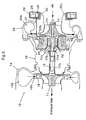
- Fig. 3 is a view of an entire structure of a motor-driven supercharger in accordance with the present invention.
- a motor-driven supercharger 10 in accordance with the present invention is provided with a turbine shaft 12, a compressor impeller 14, a bearing housing 16, a turbine housing 18 and a compressor housing 20.
- the turbine shaft 12 has a turbine impeller 11 in one end (a left end in the drawing).
- the turbine impeller 11 is integrally formed in the turbine shaft 12.
- the present invention is not limited to this, but may be structured such that the turbine impeller 11 is independently attached.
- the compressor impeller 14 is coupled to the other end (a right end in the drawing) of the turbine shaft 12 by a shaft end nut 15 so as to integrally rotate.
- the bearing housing 16 rotatably supports the turbine shaft 12 by a bearing metal 17a. Further, the turbine shaft 12 is supported by a thrust collar 17b and thrust bearings 17c and 17d so as to be immobile in an axial direction. Further, the bearing housing 16 has a lubricating fluid flow path (not shown) for lubricating the bearing metal 17a, the thrust collar 17b and the thrust bearings 17c and 17d.
- the turbine housing 18 rotatably surrounds the turbine impeller 11, and is coupled to the bearing housing 16.
- the turbine housing 18 has a scroll chamber 18a in which an exhaust gas is introduced to an inner portion from an external portion, and an annularly formed flow path 18b guiding the exhaust gas to the turbine impeller 11 from the scroll chamber 18a.
- a plurality of nozzle vanes 19 are arranged at a fixed interval in a peripheral direction.
- the nozzle vane 19 is constituted by a variable nozzle vane, and it is preferable that the nozzle vane 19 can change a flow path area formed therebetween.
- the present invention is not limited to this, but may be constituted by a fixed nozzle vane.
- the compressor housing 20 rotatably surrounds the compressor impeller 14, and is coupled to the bearing housing 16.
- the compressor housing 20 has a scroll chamber 20a in which the compressed air is introduced to an inner portion, and an annularly formed flow path 20b guiding the compressed air to the scroll chamber 20a from the compressor impeller 14.
- the motor-driven supercharger 10 in accordance with the present invention is further provided with a motor rotor 22, a motor stator 24, an inverter 26 and an inverter controller 28.
- the motor rotor 22 is fixed to the turbine shaft 12 so as to rotate together with the turbine shaft.
- the motor rotor 22 corresponds to a rotor of the electric motor.
- the motor stator 24 surrounds the motor rotor 22, is fixed within the bearing housing 16.
- the motor stator 24 corresponds to a stator of the electric motor.
- a brushless ac motor is constituted by the motor rotor 22 and the motor stator 24.
- the ac motor can correspond to a high-speed rotation (for example, at least 100 to 200 thousand rpm) of the turbine shaft 12, and can execute a rotational drive at a time of accelerating and a regenerative operation at a time of decelerating. Further, it is preferable that a drive voltage of the ac motor is equal to or higher than (for example, 24 to 36 V) a dc voltage (for example, 12 V) of a battery mounted on the vehicle. It is possible to make the ac motor compact by increasing the drive voltage.
- the inverter 26 has a function of converting a dc power of the battery mounted on the vehicle into an ac power having an optional frequency. It is preferable that the inverter 26 is constituted by an inverter of a pulse width modulation (PWM) controlling both of the frequency and the voltage.
- PWM pulse width modulation
- the present invention is not limited to this, but can employ an optional inverter, for example, a current type inverter easily executing the regenerative operation, in correspondence to the used electric motor.
- An input terminal of the inverter 26 is connected to a dc voltage (for example, 12 V) of the battery mounted on the vehicle via a power cable (not shown).
- the input voltage of the inverter may be equal or lower or higher than the dc voltage (for example, 12 V) of the battery. In this case, it is preferable that the voltage is equal with the voltage of the control system of the entire vehicle.
- An output terminal of the inverter 26 is connected to the motor stator 24 via a power supply cable 27.
- the power supply cable 27 is formed as short as possible, an electric resistance and an inductance of the power supply cable 27 is set small, and the power supply cable 27 limits the power loss to the minimum.
- the inverter controller 28 controls a frequency and a voltage of the ac power generated by the inverter 26.
- the inverter controller 28 is connected to a control device of the entire vehicle or an engine controller by a control line (not shown), and is structured such as to control the frequency and the voltage.
- the motor-driven supercharger 10 in accordance with the present invention is further provided with a driver container 29 accommodating the inverter 26 and the inverter controller 28, and an insulating coupling member 30 coupling the driver container 29 to the compressor housing 20.
- the driver container 29 is entirely formed in a donut shape or a U shape in such a manner that the driver container 29 can be attached around a cylindrical ambient air suction portion 20c of the compressor housing 20 without protruding to the external portion.
- the insulating coupling member 30 has an air-cooled or water-cooled insulating layer insulating heat in such a manner as to prevent a high temperature of the air discharged from the compressor from being transferred to the driver container 29.
- the insulating coupling member 30 further has a vibration absorption function so as to absorb a vibration of the compressor housing 20 from being transmitted to the driver container 29.
- the driver container 29 is coupled to the compressor housing 20 to which the ambient air having a comparatively low temperature is introduced, and the driver container 29 is heat insulated by the insulating coupling member 30 having the air-cooled or water-cooled insulating layer, it is possible to prevent an overheat of the driver container 29, and the inverter 26 and the inverter controller 28 in the inner portion of the driver container.
- the driver container 29 is installed in the intake side of the compressor housing, it is possible to directly introduce a part of the ambient air having the comparatively low temperature and sucked by the compressor into the inner portion of the driver, and there can be obtained an excellent effect that it is possible tc positively cool.
Landscapes
- Engineering & Computer Science (AREA)
- Mechanical Engineering (AREA)
- General Engineering & Computer Science (AREA)
- Chemical & Material Sciences (AREA)
- Combustion & Propulsion (AREA)
- Supercharger (AREA)
Applications Claiming Priority (1)
| Application Number | Priority Date | Filing Date | Title |
|---|---|---|---|
| JP2005229005A JP4605380B2 (ja) | 2005-08-08 | 2005-08-08 | 電動過給機 |
Publications (3)
| Publication Number | Publication Date |
|---|---|
| EP1752635A2 true EP1752635A2 (fr) | 2007-02-14 |
| EP1752635A3 EP1752635A3 (fr) | 2007-11-21 |
| EP1752635B1 EP1752635B1 (fr) | 2013-06-05 |
Family
ID=37192281
Family Applications (1)
| Application Number | Title | Priority Date | Filing Date |
|---|---|---|---|
| EP06016455.5A Ceased EP1752635B1 (fr) | 2005-08-08 | 2006-08-07 | Compresseur de suralimentation entraîné par un moteur |
Country Status (4)
| Country | Link |
|---|---|
| US (1) | US7352077B2 (fr) |
| EP (1) | EP1752635B1 (fr) |
| JP (1) | JP4605380B2 (fr) |
| CN (1) | CN100557211C (fr) |
Cited By (2)
| Publication number | Priority date | Publication date | Assignee | Title |
|---|---|---|---|---|
| WO2012095383A1 (fr) * | 2011-01-13 | 2012-07-19 | Continental Automotive Gmbh | Turbocompresseur à gaz d'échappement pourvu d'un carter de compression à actionneur de soupape de dérivation intégré |
| EP2025892A4 (fr) * | 2006-06-02 | 2013-06-19 | Ihi Corp | Compresseur à suralimentation électrique |
Families Citing this family (41)
| Publication number | Priority date | Publication date | Assignee | Title |
|---|---|---|---|---|
| US7458214B2 (en) * | 2003-04-15 | 2008-12-02 | Honeywell International, Inc. | Electric motor cartridge for an electrically assisted turbocharger |
| US8029252B2 (en) * | 2003-09-05 | 2011-10-04 | Honeywell International Inc. | Electric power connection for electrically assisted turbocharger |
| DE602006020239D1 (de) * | 2006-01-24 | 2011-04-07 | Ihi Corp | Motorbetriebene Aufladung |
| DE602006008264D1 (de) | 2006-01-26 | 2009-09-17 | Ihi Corp | Turbo-Auflader |
| EP1998008B1 (fr) * | 2006-03-23 | 2019-03-13 | IHI Corporation | Argencement d'arbre à haute vitesse de rotation pour turbocompresseur |
| JP4671177B2 (ja) * | 2006-06-02 | 2011-04-13 | 株式会社Ihi | 電動過給機 |
| JP4941782B2 (ja) | 2006-08-18 | 2012-05-30 | 株式会社Ihi | 電動過給機 |
| KR20090039770A (ko) * | 2006-08-18 | 2009-04-22 | 가부시키가이샤 아이에이치아이 | 전동 과급기 |
| JP2009167971A (ja) * | 2008-01-18 | 2009-07-30 | Ihi Corp | ハウジング締結方法及び過給機 |
| EP2241735A4 (fr) * | 2008-01-28 | 2017-08-02 | IHI Corporation | Compresseur volumétrique |
| US8341949B2 (en) * | 2008-05-30 | 2013-01-01 | Caterpillar Inc. | After-treatment system |
| DE102008034680A1 (de) * | 2008-07-25 | 2010-06-10 | Continental Mechanical Components Germany Gmbh | Gekühltes Turboladergehäuse mit einer oder mehreren Elektronikeinrichtungen |
| JP5260198B2 (ja) | 2008-09-08 | 2013-08-14 | 三菱重工業株式会社 | インバータ一体型電動圧縮機 |
| US20100089056A1 (en) * | 2008-10-09 | 2010-04-15 | General Electric Company | Integrated turbo-boosting and electric generation system and method |
| JP4916554B2 (ja) * | 2010-01-15 | 2012-04-11 | 三菱電機株式会社 | 電動過給機の電源制御装置 |
| US9951784B2 (en) * | 2010-07-27 | 2018-04-24 | R&D Dynamics Corporation | Mechanically-coupled turbomachinery configurations and cooling methods for hermetically-sealed high-temperature operation |
| JP2012062777A (ja) * | 2010-09-14 | 2012-03-29 | Mitsubishi Electric Corp | 電動過給機 |
| JP5529714B2 (ja) * | 2010-11-12 | 2014-06-25 | 三菱重工業株式会社 | 電動過給機の回転軸支持構造 |
| TWI482903B (zh) * | 2011-12-06 | 2015-05-01 | Hon Hai Prec Ind Co Ltd | 燃氣渦輪機模組 |
| US9470231B2 (en) | 2012-01-06 | 2016-10-18 | Borgwarner Inc. | Electrically assisted turbocharger |
| CN104145099B (zh) | 2012-02-17 | 2017-11-07 | 博格华纳公司 | 多部段涡轮增压器轴承壳体以及其方法 |
| JP2016503144A (ja) * | 2013-01-10 | 2016-02-01 | トロトラック・(ディベロップメント)・リミテッド | スーパーチャージャー用の駆動構造 |
| KR101429848B1 (ko) * | 2013-02-13 | 2014-08-12 | 한승주 | 자기 구동 확장공기충전장치 |
| DE102013210990A1 (de) * | 2013-06-13 | 2014-12-18 | Continental Automotive Gmbh | Abgasturbolader mit einem Radial-Axial-Turbinenrad |
| DE102013219609B4 (de) | 2013-09-27 | 2021-01-14 | Vitesco Technologies GmbH | Verfahren zum Betreiben einer Schaltungsanordnung zum Laden und Entladen eines kapazitiven Aktuators |
| US20150292392A1 (en) * | 2014-04-15 | 2015-10-15 | Arnold Magnetic Technologies | Throttle control system and method |
| JP6536737B2 (ja) * | 2016-02-19 | 2019-07-03 | 株式会社Ihi | 締結構造および電動過給機 |
| US20180106263A1 (en) * | 2016-10-14 | 2018-04-19 | Borgwarner Inc. | Single piece bearing housing with turbine end plate |
| US10508590B2 (en) | 2017-02-07 | 2019-12-17 | Kohler Co. | Forced induction engine with electric motor for compressor |
| US10704556B2 (en) * | 2017-08-30 | 2020-07-07 | Mitsubishi Heavy Industries, Ltd. | Motor, turbocharger and assembly method turbocharger |
| DE102019004250A1 (de) * | 2019-06-14 | 2020-12-17 | Daimler Ag | Strömungsmaschine, insbesondere Abgasturbolader, für ein Kraftfahrzeug sowie Kraftfahrzeug |
| EP3967859A1 (fr) | 2020-09-14 | 2022-03-16 | BMTS Technology GmbH & Co. KG | Unité électronique pour contrôler et faire fonctionner un moteur électrique |
| US11781565B2 (en) * | 2021-06-28 | 2023-10-10 | Garrett Transportation I Inc. | Integrated e-machine controller for turbomachine having fastener arrangement for electronics components |
| US12132376B2 (en) | 2021-06-28 | 2024-10-29 | Garrett Transportation I Inc. | Integrated e-machine controller for turbomachine having fastening arrangement |
| US11668323B2 (en) | 2021-06-28 | 2023-06-06 | Garrett Transportation I Inc. | Coolant system for integrated e-machine controller for turbomachine |
| US12082360B2 (en) * | 2021-09-10 | 2024-09-03 | Garrett Transportation I Inc | Resilient printed circuit board retention arrangement |
| US11655734B1 (en) * | 2021-12-09 | 2023-05-23 | Garrett Transportation I Inc | Integrated e-machine controller for turbomachine with thermally de-coupled fastener arrangement |
| CN114215637A (zh) * | 2021-12-30 | 2022-03-22 | 康跃科技(山东)有限公司 | 一种电辅助增压器低温冷却结构 |
| CN116510471B (zh) * | 2023-06-02 | 2024-03-29 | 东营市通海盈信新能源有限公司 | 一种油田伴生气脱碳系统 |
| US12221982B1 (en) * | 2023-08-08 | 2025-02-11 | Garrett Transportation I Inc. | Turbocharger having compressor with liquid-cooled backplate |
| US12392283B1 (en) * | 2024-05-15 | 2025-08-19 | Flowserve Pte. Ltd. | Energy recovery turbocharger with integral motor/generator |
Citations (1)
| Publication number | Priority date | Publication date | Assignee | Title |
|---|---|---|---|---|
| EP0212988A2 (fr) | 1985-08-30 | 1987-03-04 | Isuzu Motors Limited | Dispositif de commande de turbocompresseur pour moteur à combustion interne |
Family Cites Families (47)
| Publication number | Priority date | Publication date | Assignee | Title |
|---|---|---|---|---|
| US2121605A (en) * | 1936-05-15 | 1938-06-21 | English Electric Co Ltd | Electric traction motor control system |
| DE2823261C2 (de) | 1978-05-27 | 1985-05-23 | Robert Bosch Gmbh, 7000 Stuttgart | Elektrische Maschine |
| JPS57115523A (en) | 1981-01-09 | 1982-07-19 | Nippon Kogaku Kk <Nikon> | Automatic focussing camera possible for manual focussing |
| EP0210833B1 (fr) * | 1985-07-26 | 1991-06-26 | Isuzu Motors Limited | Système de commande pour un moteur à combustion interne suralimenté |
| KR900001291B1 (ko) * | 1985-08-28 | 1990-03-05 | 이스즈지도샤 가부시끼가이샤 | 내연기관의 보조장치 |
| JPS6419122A (en) | 1987-07-13 | 1989-01-23 | Isuzu Motors Ltd | Turbocharger with revolving armature |
| JPH0299722A (ja) | 1988-10-07 | 1990-04-11 | Isuzu Ceramics Kenkyusho:Kk | ターボチャージャ |
| JPH02241339A (ja) | 1989-03-14 | 1990-09-26 | Hitachi Ltd | ターボチャージヤ直結回転機用永久磁石回転子 |
| JPH066898B2 (ja) * | 1989-05-10 | 1994-01-26 | いすゞ自動車株式会社 | ターボチャージャ駆動用電源装置 |
| JPH03138430A (ja) * | 1989-10-23 | 1991-06-12 | Isuzu Ceramics Kenkyusho:Kk | 事務用移動車両 |
| DE4115273C1 (fr) | 1991-05-10 | 1992-06-04 | J.M. Voith Gmbh, 7920 Heidenheim, De | |
| JPH05280362A (ja) * | 1992-03-31 | 1993-10-26 | Isuzu Motors Ltd | ターボチャージャ用回転電機の電圧制御装置 |
| JPH06346748A (ja) * | 1993-06-03 | 1994-12-20 | Isuzu Motors Ltd | タ−ボ用回転電機の電力部制御装置 |
| JP3166450B2 (ja) * | 1993-10-04 | 2001-05-14 | いすゞ自動車株式会社 | 排気エネルギー回収装置 |
| JP3337811B2 (ja) * | 1994-03-28 | 2002-10-28 | マツダ株式会社 | エンジンの過給装置 |
| JP3389748B2 (ja) * | 1995-07-12 | 2003-03-24 | いすゞ自動車株式会社 | 排気エネルギー回収装置 |
| US6032466A (en) | 1996-07-16 | 2000-03-07 | Turbodyne Systems, Inc. | Motor-assisted turbochargers for internal combustion engines |
| US5870894A (en) | 1996-07-16 | 1999-02-16 | Turbodyne Systems, Inc. | Motor-assisted supercharging devices for internal combustion engines |
| US5904471A (en) | 1996-12-20 | 1999-05-18 | Turbodyne Systems, Inc. | Cooling means for a motor-driven centrifugal air compressor |
| US5857332A (en) | 1996-12-20 | 1999-01-12 | Turbodyne Systems, Inc. | Bearing systems for motor-assisted turbochargers for internal combustion engines |
| US5798587A (en) | 1997-01-22 | 1998-08-25 | Industrial Technology Research Institute | Cooling loop structure of high speed spindle |
| US6102672A (en) | 1997-09-10 | 2000-08-15 | Turbodyne Systems, Inc. | Motor-driven centrifugal air compressor with internal cooling airflow |
| DE19845375A1 (de) | 1998-10-02 | 2000-04-06 | Asea Brown Boveri | Verfahren und Vorrichtung zur indirekten Kühlung der Strömung in zwischen Rotoren und Statoren von Turbomaschinen ausgebildeten Radialspalten |
| JP2000130176A (ja) | 1998-10-30 | 2000-05-09 | Isuzu Motors Ltd | 発電・電動機を備えたターボチャージャ |
| JP3877894B2 (ja) | 1999-01-13 | 2007-02-07 | 三菱電機株式会社 | 車両用ブラシレス交流発電機 |
| US6278199B1 (en) * | 1999-02-25 | 2001-08-21 | International Rectifier Corp. | Electronic single switch module |
| JP3877899B2 (ja) | 1999-03-09 | 2007-02-07 | 三菱電機株式会社 | 車両用交流発電機 |
| DE10003153A1 (de) | 2000-01-26 | 2001-08-02 | Leybold Vakuum Gmbh | Turboradialgebläse |
| DE10022113A1 (de) * | 2000-05-06 | 2001-11-15 | Daimler Chrysler Ag | Hybridantrieb für Kraftfahrzeuge |
| US6449950B1 (en) | 2000-09-12 | 2002-09-17 | Honeywell International Inc. | Rotor and bearing system for electrically assisted turbocharger |
| US6609375B2 (en) | 2001-09-14 | 2003-08-26 | Honeywell International Inc. | Air cooling system for electric assisted turbocharger |
| DE10156704A1 (de) | 2001-11-13 | 2003-05-22 | Iav Gmbh | Verfahren und Vorrichtung zum Betreiben eines Abgasturboladers für Verbrennungskraftmaschinen mit elektrisch unterstütztem Antrieb |
| JP3843932B2 (ja) | 2002-03-26 | 2006-11-08 | トヨタ自動車株式会社 | ターボチャージャ |
| JP2003293785A (ja) | 2002-04-03 | 2003-10-15 | Toyota Motor Corp | ターボチャージャ |
| JP2004044452A (ja) | 2002-07-10 | 2004-02-12 | Ishikawajima Harima Heavy Ind Co Ltd | 過給機 |
| JP4061994B2 (ja) | 2002-07-10 | 2008-03-19 | 株式会社Ihi | 過給機 |
| US6647724B1 (en) * | 2002-07-30 | 2003-11-18 | Honeywell International Inc. | Electric boost and/or generator |
| US6668553B1 (en) | 2002-09-13 | 2003-12-30 | Honeywell International Inc. | Ejector-based cooling system for turbochargers |
| US7458214B2 (en) | 2003-04-15 | 2008-12-02 | Honeywell International, Inc. | Electric motor cartridge for an electrically assisted turbocharger |
| DE10325980A1 (de) | 2003-06-07 | 2004-12-23 | Daimlerchrysler Ag | Abgasturbolader |
| JP2005042684A (ja) * | 2003-07-25 | 2005-02-17 | Denso Corp | 電動機付ターボチャージャの電力制御装置および電動ターボチャージャ装置 |
| JP2005069178A (ja) | 2003-08-27 | 2005-03-17 | Toyota Motor Corp | 電動機付過給機 |
| US8029252B2 (en) | 2003-09-05 | 2011-10-04 | Honeywell International Inc. | Electric power connection for electrically assisted turbocharger |
| JP4182846B2 (ja) * | 2003-09-05 | 2008-11-19 | トヨタ自動車株式会社 | 内燃機関の制御装置 |
| WO2005028876A1 (fr) | 2003-09-25 | 2005-03-31 | Abb Research Ltd. | Nettoyage de compresseur |
| JP4692820B2 (ja) | 2005-08-11 | 2011-06-01 | 株式会社Ihi | 電動機付過給機 |
| DE102005052363A1 (de) | 2005-11-02 | 2007-05-03 | Siemens Ag | Elektromotor |
-
2005
- 2005-08-08 JP JP2005229005A patent/JP4605380B2/ja not_active Expired - Fee Related
-
2006
- 2006-08-07 EP EP06016455.5A patent/EP1752635B1/fr not_active Ceased
- 2006-08-08 CN CNB200610114836XA patent/CN100557211C/zh not_active Expired - Fee Related
- 2006-08-08 US US11/463,090 patent/US7352077B2/en active Active
Patent Citations (1)
| Publication number | Priority date | Publication date | Assignee | Title |
|---|---|---|---|---|
| EP0212988A2 (fr) | 1985-08-30 | 1987-03-04 | Isuzu Motors Limited | Dispositif de commande de turbocompresseur pour moteur à combustion interne |
Cited By (2)
| Publication number | Priority date | Publication date | Assignee | Title |
|---|---|---|---|---|
| EP2025892A4 (fr) * | 2006-06-02 | 2013-06-19 | Ihi Corp | Compresseur à suralimentation électrique |
| WO2012095383A1 (fr) * | 2011-01-13 | 2012-07-19 | Continental Automotive Gmbh | Turbocompresseur à gaz d'échappement pourvu d'un carter de compression à actionneur de soupape de dérivation intégré |
Also Published As
| Publication number | Publication date |
|---|---|
| CN100557211C (zh) | 2009-11-04 |
| EP1752635B1 (fr) | 2013-06-05 |
| EP1752635A3 (fr) | 2007-11-21 |
| CN1912364A (zh) | 2007-02-14 |
| JP4605380B2 (ja) | 2011-01-05 |
| JP2007046479A (ja) | 2007-02-22 |
| US20070108772A1 (en) | 2007-05-17 |
| US7352077B2 (en) | 2008-04-01 |
Similar Documents
| Publication | Publication Date | Title |
|---|---|---|
| EP1752635B1 (fr) | Compresseur de suralimentation entraîné par un moteur | |
| EP2025891B1 (fr) | Compresseur à suralimentation électrique | |
| CN100434700C (zh) | 具有内冷空气流的马达驱动离心空气压缩机 | |
| CN107110011B (zh) | 涡轮增压器 | |
| EP2067960B1 (fr) | Dispositif de suralimentation électrique | |
| EP2247838B1 (fr) | Groupe de suralimentation pour un moteur a piston | |
| KR101324226B1 (ko) | 유체 과급 장치 | |
| EP2025892A1 (fr) | Compresseur à suralimentation électrique | |
| CN107250505B (zh) | 用于驱动装置的增压器、尤其是废气涡轮增压器以及相应的驱动装置 | |
| GB2354553A (en) | Electric motor driven turbocharger. | |
| EP1762713A2 (fr) | Structure de palier pour turbo compresseur entraîné par un moteur | |
| JP2004516406A (ja) | 電気駆動式流体圧縮機 | |
| KR19990068855A (ko) | 내연기관용모터보조식터보냉각시스템 | |
| KR100923188B1 (ko) | 전동 과급기 | |
| US20260031671A1 (en) | Stator cooled electric motor | |
| US20210180511A1 (en) | Turbocharger | |
| CN108700080A (zh) | 电动压缩机 | |
| KR20040090066A (ko) | 연료 전지용 가스 공급 장치 |
Legal Events
| Date | Code | Title | Description |
|---|---|---|---|
| PUAI | Public reference made under article 153(3) epc to a published international application that has entered the european phase |
Free format text: ORIGINAL CODE: 0009012 |
|
| AK | Designated contracting states |
Kind code of ref document: A2 Designated state(s): AT BE BG CH CY CZ DE DK EE ES FI FR GB GR HU IE IS IT LI LT LU LV MC NL PL PT RO SE SI SK TR |
|
| AX | Request for extension of the european patent |
Extension state: AL BA HR MK YU |
|
| RAP1 | Party data changed (applicant data changed or rights of an application transferred) |
Owner name: IHI CORPORATION |
|
| PUAL | Search report despatched |
Free format text: ORIGINAL CODE: 0009013 |
|
| AK | Designated contracting states |
Kind code of ref document: A3 Designated state(s): AT BE BG CH CY CZ DE DK EE ES FI FR GB GR HU IE IS IT LI LT LU LV MC NL PL PT RO SE SI SK TR |
|
| AX | Request for extension of the european patent |
Extension state: AL BA HR MK YU |
|
| RIC1 | Information provided on ipc code assigned before grant |
Ipc: F02B 39/16 20060101ALI20071015BHEP Ipc: F02B 37/04 20060101ALI20071015BHEP Ipc: F02B 39/10 20060101AFI20061106BHEP |
|
| 17P | Request for examination filed |
Effective date: 20080306 |
|
| AKX | Designation fees paid |
Designated state(s): DE FR IT |
|
| 17Q | First examination report despatched |
Effective date: 20091222 |
|
| GRAP | Despatch of communication of intention to grant a patent |
Free format text: ORIGINAL CODE: EPIDOSNIGR1 |
|
| GRAS | Grant fee paid |
Free format text: ORIGINAL CODE: EPIDOSNIGR3 |
|
| GRAA | (expected) grant |
Free format text: ORIGINAL CODE: 0009210 |
|
| AK | Designated contracting states |
Kind code of ref document: B1 Designated state(s): DE FR IT |
|
| REG | Reference to a national code |
Ref country code: DE Ref legal event code: R096 Ref document number: 602006036629 Country of ref document: DE Effective date: 20130801 |
|
| PLBE | No opposition filed within time limit |
Free format text: ORIGINAL CODE: 0009261 |
|
| STAA | Information on the status of an ep patent application or granted ep patent |
Free format text: STATUS: NO OPPOSITION FILED WITHIN TIME LIMIT |
|
| 26N | No opposition filed |
Effective date: 20140306 |
|
| REG | Reference to a national code |
Ref country code: DE Ref legal event code: R097 Ref document number: 602006036629 Country of ref document: DE Effective date: 20140306 |
|
| REG | Reference to a national code |
Ref country code: FR Ref legal event code: PLFP Year of fee payment: 11 |
|
| REG | Reference to a national code |
Ref country code: FR Ref legal event code: PLFP Year of fee payment: 12 |
|
| REG | Reference to a national code |
Ref country code: FR Ref legal event code: PLFP Year of fee payment: 13 |
|
| PGFP | Annual fee paid to national office [announced via postgrant information from national office to epo] |
Ref country code: FR Payment date: 20180712 Year of fee payment: 13 Ref country code: IT Payment date: 20180823 Year of fee payment: 13 |
|
| PG25 | Lapsed in a contracting state [announced via postgrant information from national office to epo] |
Ref country code: FR Free format text: LAPSE BECAUSE OF NON-PAYMENT OF DUE FEES Effective date: 20190831 |
|
| PG25 | Lapsed in a contracting state [announced via postgrant information from national office to epo] |
Ref country code: IT Free format text: LAPSE BECAUSE OF NON-PAYMENT OF DUE FEES Effective date: 20190807 |
|
| PGFP | Annual fee paid to national office [announced via postgrant information from national office to epo] |
Ref country code: DE Payment date: 20220629 Year of fee payment: 17 |
|
| REG | Reference to a national code |
Ref country code: DE Ref legal event code: R119 Ref document number: 602006036629 Country of ref document: DE |
|
| PG25 | Lapsed in a contracting state [announced via postgrant information from national office to epo] |
Ref country code: DE Free format text: LAPSE BECAUSE OF NON-PAYMENT OF DUE FEES Effective date: 20240301 |