EP1755817B1 - Drahtfördervorrichtung - Google Patents
Drahtfördervorrichtung Download PDFInfo
- Publication number
- EP1755817B1 EP1755817B1 EP05750208A EP05750208A EP1755817B1 EP 1755817 B1 EP1755817 B1 EP 1755817B1 EP 05750208 A EP05750208 A EP 05750208A EP 05750208 A EP05750208 A EP 05750208A EP 1755817 B1 EP1755817 B1 EP 1755817B1
- Authority
- EP
- European Patent Office
- Prior art keywords
- wire
- pressure
- welding
- transport device
- transport
- Prior art date
- Legal status (The legal status is an assumption and is not a legal conclusion. Google has not performed a legal analysis and makes no representation as to the accuracy of the status listed.)
- Expired - Lifetime
Links
Images


Classifications
-
- B—PERFORMING OPERATIONS; TRANSPORTING
- B23—MACHINE TOOLS; METAL-WORKING NOT OTHERWISE PROVIDED FOR
- B23K—SOLDERING OR UNSOLDERING; WELDING; CLADDING OR PLATING BY SOLDERING OR WELDING; CUTTING BY APPLYING HEAT LOCALLY, e.g. FLAME CUTTING; WORKING BY LASER BEAM
- B23K9/00—Arc welding or cutting
- B23K9/12—Automatic feeding or moving of electrodes or work for spot or seam welding or cutting
- B23K9/133—Means for feeding electrodes, e.g. drums, rolls, motors
- B23K9/1336—Driving means
-
- B—PERFORMING OPERATIONS; TRANSPORTING
- B23—MACHINE TOOLS; METAL-WORKING NOT OTHERWISE PROVIDED FOR
- B23K—SOLDERING OR UNSOLDERING; WELDING; CLADDING OR PLATING BY SOLDERING OR WELDING; CUTTING BY APPLYING HEAT LOCALLY, e.g. FLAME CUTTING; WORKING BY LASER BEAM
- B23K2101/00—Articles made by soldering, welding or cutting
- B23K2101/36—Electric or electronic devices
- B23K2101/40—Semiconductor devices
Definitions
- the invention relates to a wire feed device for transporting a wire, in particular a welding wire, by means of funding from a wire supply to a consumer point, with an adjusting device for adjusting the contact pressure of the conveying means on the welding wire.
- Wire feeding devices are also known in which different welding wires could be conveyed with the aid of resilient elements which press on conveying means. However, this makes the contact pressure for a thicker wire diameter much higher than for a thinner wire. Furthermore, these wire feeders can not affect the weld wire composition, ie, for example, with a high aluminum weld wire, the surface of the weld wire can be deformed much more easily than a weld wire with a high proportion of stronger members than aluminum.
- these wire feeding devices promote welding wires of different diameters and also of different compositions, it is not possible to influence the contact pressure, as a result of which deformations of the welding wire can occur, for example, if the contact pressure is too high and, for example, if the contact pressure is too low it can happen that the conveying means slip through, So have a high slip, whereby no constant welding wire delivery can be made possible.
- EP 1 206 993 A a wire conveying device of the subject type in which an adjustment of the contact pressure on the welding wire, in particular when using welding wires with different diameters is not provided.
- US 2,272,158 A shows a device for conveying a welding wire in which no adjustment of the contact pressure is provided on the welding wire.
- the tension of the contact pressure of the conveyor on the welding wire used should be automatic and be controlled independently by the welding machine.
- the adjusting device has at least one elastically or plastically deformable pressure means acting on the conveying means, which is connected to a supply unit.
- the advantage is that a simple, known from the prior art pressure means can be used, which is designed in a simple manner and thus the wire feed device is automatically adjusted to the inserted or inserted welding wire.
- Another advantage is that when changing the welding wire, so if another welding wire is needed for a welding process, no parts of the wire feeding device for easy wire feeding must be replaced, resulting in a much simplified handling of the wire feeding device.
- the pressure medium is advantageously arranged between a conveyor and a support surface or a support element on the opposite side of the conveyor.
- connection between the pressure medium and the supply unit can be made via lines and / or bores and / or flow channels.
- the plastically or elastically deformable pressure medium can be formed by a pressure hose or a pneumatic pad. This can be done with the pressure means a simple pressure control and thus a simple adaptation to the respective welding wires used. There must be no parts of the wire conveyor be changed when changing the welding wire in particular larger or smaller welding wire diameter material. As a result, a very cost-effective construction of the pressure conveying device can be realized and at the same time an exact pressure adjustment of the contact pressure in a simple form can be made possible.
- the pressure hose is advantageously closed at one end and has a filling support for the supply of a medium.
- the pressure control of the pressure medium can be carried out by adding or removing the medium in a simple manner.
- the filling supports can be connected via a line to a container having the medium, which forms the supply unit.
- the container forming the supply unit can be arranged both in the welding device and outside of the welding device.
- the container may be formed from a gas cylinder or a pressure vessel.
- a container known from the prior art for the medium can be used, for which purpose an independent pressure system for the pressure adjustment of the pressure medium is provided.
- the medium arranged in the pressure medium is formed by a gas, no additional container or pressure vessel is required, since the gas or inert gas used for the welding process can be used to build up the pressure in the pressure medium.
- a liquid can be used, thereby creating a simple and renewable or refillable medium at any time.
- the conveyor may be formed by rollers or, for example, in a conveyor element circumferentially arranged elements. This ensures safe delivery of the welding wire.
- the pressing force of the conveying means is adjustable on the respective welding wire on the welding apparatus and / or on a control device and / or on a control panel and / or on a remote control.
- the thickness and the material of the welding wire used are entered.
- a device for regulating the contact pressure of the conveying means which regulates the contact pressure as a function of the set values for the welding wire used, in particular the thickness and / or the material. From the user of the welding device, only the welding wire used must be disclosed, so for example, the material used and the thickness used or the diameter of the welding wire are entered, whereupon the welding device or the control device, an automatic control of the contact pressure is performed.
- a device for detecting the actual value of the pressure of the conveying means on the welding wire or also a device for detecting the actual value of the welding wire speed is arranged.
- the wire conveying speed and thus also, for example, the slippage of the conveying means can be determined and the pressure of the adjusting device can be adjusted by the welding device and / or the control device and / or the operating panel.
- the contact pressure can be increased in spinning conveyor means, whereby the slip is reduced.
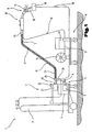
- Fig. 1 is a welding machine 1 or a welding system for a variety of processes or procedures, such as MIG / MAG welding or TIG / TIG welding or electrode welding process, double wire / tandem welding process, plasma or soldering, etc., shown.
- the welding device 1 comprises a current source 2 with a power part 3, a control device 4 and a switching element 5 assigned to the power part 3 or the control device 4.
- the switching element 5 or the control device 4 is connected to a control valve 6 which is located in a supply line 7 for a gas 8, in particular a protective gas, such as CO 2, helium or argon and the like., Between a gas storage 9 and a welding torch 10 and a burner is arranged.
- a wire feed device 11 which is customary for MIG / MAG welding, are controlled, via a supply line 12, a filler material or a welding wire 13 from a wire supply 14 or a wire roller in the region of the welding torch 10 is supplied.
- the wire feeder 11 as is known from the prior art, in the welding device 1, in particular in the base housing, is integrated and not, as in Fig. 1 shown, is designed as an accessory.
- the wire feeder 11 may supply the welding wire 13 or the additional material outside the welding torch 10 to the processing station, wherein a non-consumable electrode is preferably arranged in the welding torch 10, as is customary in TIG / TIG welding.
- the current for constructing an arc 15, in particular a working arc, between the electrode and a workpiece 16 is supplied via a welding line 17 from the power section 3 of the power source 2 to the burner 10, in particular the electrode, wherein the workpiece to be welded 16, which consists of several Parts is formed, via a further welding line 18 is also connected to the welding device 1, in particular with the power source 2, and thus via the arc 15 and the plasma jet formed for a process, a circuit can be constructed.
- the welding torch 10 can be connected via a cooling circuit 20 to a liquid container, in particular a water tank 21, whereby during commissioning of the welding torch 10 the cooling circuit 19, in particular a liquid arranged in the water tank 21 used liquid pump is started, and thus a cooling of the welding torch 10 can be effected.
- the welding device 1 further has an input and / or output device 22, via which the most varied welding parameters, operating modes or welding programs of the welding device 1 can be set or called up.
- the set via the input and / or output device 22 welding parameters, operating modes or welding programs are forwarded to the control device 4 and from this then the individual components of the welding system or the welding device 1 driven or specified setpoints for the control or regulation.
- the welding torch 10 is connected via a hose package 23 to the welding device 1 or the welding system.
- the individual lines from the welding device 1 to the welding torch 10 are arranged.
- the hose package 23 is connected via a coupling device 24 to the welding torch 10, whereas the individual lines in the hose package 23 are connected to the individual contacts of the welding device 1 via connection sockets or plug connections. So that a corresponding strain relief of the hose assembly 23 is ensured, the hose package 23 is connected via a strain relief device 25 with a housing 26, in particular with the base housing of the welding device 1.
- the coupling device 24 can also be used for the connection to the welding device 1.
- the welding torch 10 can be designed as an air-cooled welding torch 10.
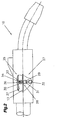
- Fig. 2 shows a welding torch 10 in a simplified and schematically illustrated side view.
- a wire feed device 27 is arranged in this embodiment.
- a conveying means 28 which consists of at least one drive roller 29 and at least one pressure roller 30, is arranged in the wire conveying device 27.
- the drive roller 29 is while rotatably connected to a shaft 31.
- the shaft 31 may be connected, for example via a transmission with a drive 32, in particular a drive motor or else directly to the drive 32.
- the pressure roller 30 is arranged on the welding wire 13 opposite side of the drive roller 29.
- the pressure roller 30 is movably arranged in the direction of the welding wire 13 and mounted on a further shaft 33, wherein the shaft 33 along an example of a groove 34 is arranged adjustable.
- the pressure means 36 may be formed plastically or elastically deformable and is disposed between the conveyor 28, in particular the pressure roller 30, and on a support surface or a support member 37 of the conveyor 28 opposite side.
- the pressure roller 30 presses by means of the pressure means 36 on the inserted into the wire feed device 27 welding wire 13 and thus thus against the drive roller 29.
- the welding wire 13 is clamped in the conveyor 28 and by the drive roller 29 in the respective direction, ie for example in the direction of the workpiece 16 or in the opposite direction.
- the pressure medium 36 In order to be able to convey a welding wire 13 with other properties, the pressure medium 36 must be replaced so that again the pressure required for a smooth wire feeding pressure is achieved on the welding wire 13 and thus a secure and uncomplicated promotion of the welding wire 13 is ensured.
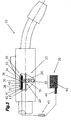
- the pressure medium 36 is formed from a pressure hose 38.
- the pressure medium 36 or the pressure hose 38 is in turn arranged between the conveyor 28, in particular the pressure roller 30, and the support element 37 and connected to a supply unit 39, in particular a container, via a line 40 and / or holes and / or flow channels.
- the supply unit 39 or the container can be arranged, for example, in the welding apparatus 1 or else outside the welding apparatus 1, but this arrangement is not in this embodiment shown.
- the pressure hose 38 is closed at one end and has a filler neck 41 at the end facing the conduit 40. On this filler 41, the line 40 is now pushed and fixed.
- the pressure medium 36 so the pressure hose 38, and the filler neck 41 via the line 40 to the supply unit 39, which in the welding machine 1 or outside, so it can be arranged externally connected.
- a medium 42 is arranged, which is now introduced via the line 40 into the pressure hose 38.
- a valve in particular a proportional pressure control valve 43 arranged. The description of the proportional pressure control valve 43 is not discussed in more detail, since this is well known from the prior art.
- the pressure control valve 43 can be arranged in the supply unit 39 and / or in the line 40.
- the inserted welding wire 13 in the welding device 1 or in the control device 4 is entered by the user and the welding device 1 or the control device 4 regulates the contact pressure of the conveyor 28, in particular the pressure roller 30 on the welding wire 13 independently.
- the welding device 1 or the control device 4 and the control device 4 controlled pressure control valve 43 automatically regulates the pressure, in particular the contact pressure of the conveyor 28, in particular the pressure roller 30 on the welding wire 13. This ensures safe delivery of the welding wire 13, without that the pressure roller 30 and the drive roller 29 slip or deform the welding wire 13.
- the proportional pressure control valve 43 instead of the proportional pressure control valve 43 to arrange all known from the prior art means for pressure build-up in the pressure medium 36.
- the pressure build-up in the pressure medium 36 can also be realized in such a way that a hand pump is used instead of the pressure control valve 43. This allows the user to regulate the pressure individually by means of the hand pump.
- a device for detecting the actual value of the pressure in the line 40, that is, between the pressure regulating valve 43 and the filling nozzle 41, can be arranged, and the actual pressure value can be displayed, for example, via a pressure gauge.
- the medium used 42 may for example be formed from a liquid, but it is also possible to use a gaseous medium 42 in the pressure medium 36.
- the protective gas of the welding process can be used as medium 42. Since only small amounts of medium 42 are needed for smooth pressure adjustment, the welding process is in no way affected.
- the supply unit 39 may be formed of a gas cylinder or a pressure vessel.
- the pressure medium 38 can also be formed from a known from the prior art pneumatic pad, which also has a filler neck 41, via which it can be filled with the medium 42.
- the pneumatic pad may in turn be provided with a liquid or gaseous medium 42, e.g. Air or a gas filled and controlled by the welding device 1 and the control device 4 and regulated.
- a liquid or gaseous medium 42 e.g. Air or a gas filled and controlled by the welding device 1 and the control device 4 and regulated.
- Fig. 4 and 5 show a further embodiment of the inventive wire feeding device 27 with automatic pressure adjustment to the welding wire 13, in a schematic and simplified form.
- the wire feed device 27 is formed from a base body 44, wherein in a central recess 45 of the base body 44, a holding element 46 is inserted.
- the holding element 46 is mounted, for example via at least one bearing 47 in the interior of the main body 44.
- the at least one bearing 47 is thereby secured against falling out by means of rings 48 arranged in the recess 45 of the base body 44.
- These rings 48 may be formed by known saw rings.
- the holding element 46 protrudes on both sides beyond the main body 44.
- On one side of a receptacle 49 is arranged, which is rotatably connected to the holding element 46.
- a thread 50 may be arranged normal to the welding wire 13 in the receptacle 49, in which a worm screw 68 is screwed into contact with the holding element 46 and thus rotatably connects the receptacle 49 with the holding element 46.
- a receiving element 51 is arranged, on which a retaining ring 52 is pushed.
- the receiving element 51 further has an extension 53, on which the pressure medium 36, in particular the pressure hose 38 is pushed.
- the pressure hose 38 protrudes from the receiving element 50 to at least one conveying element 54 or at least one pressure element 55.
- the conveying element 54 and the pressure element 55 are arranged in the holding element 46 around the welding wire 13 around.
- a bore 56 is arranged, which opens into a further radially arranged bore 57.
- the retaining ring 52 at least one circumferential groove 58 is arranged, in which the bore 57 opens.
- two further grooves 59 may be arranged, which are formed for example as a seal against the groove 58 and in which, for example, a known O-ring can be used.
- a supply bore 60 is arranged normal to the central axis of the holding element 46, which opens into the groove 58.
- the medium 42 is introduced into the groove 58 and passes through the bore 57 in the receiving element 51 to the bore 56 and over the extension 53 in the pressure hose 38.
- a pressure element 55 and two conveyor elements 54 are arranged, for example, at 120 ° around the welding wire 13 around.
- the conveying elements 54 are arranged rigidly in the holding element 46, while the pressure element 55 is mounted in the direction of the welding wire 13 towards movable in the holding element 46.
- a pressure on the pressure element 55 is exerted, which in turn exerts a pressure on the welding wire 13, whereby an operative connection between the welding wire 13, the or the conveying elements 54 and the pressure element 55 is formed.
- the welding wire 13 is thus driven by the conveyor elements 54 and the pressure element 55 and thus promoted.
- elements 61 are arranged running along a guideway and extend partially outside the conveying element 54 on the side facing the welding wire 13.
- the elements 61 run so far outside the conveyor element 54 that they can not fall out of the conveyor element 54, but touch the welding wire 13.
- the elements 61 On the opposite side of the welding wire 13 of the conveying element 54, the elements 61 in turn partially outside of the conveyor element 54 and engage in an internal thread 62, which is disposed in the interior of the main body 44 of the wire conveyor 27, ie in the recess 45.
- the elements 61 engaging in the internal thread 62 are now displaced along the guide track of the conveyor element 54.
- the welding wire 13 is moved by the force acting on the welding wire 13 elements 61 and the resulting active compound, in particular promoted.
- the pressure element 55 is formed in this embodiment of at least two parts, between which at least one roller 63 is arranged.
- the at least one roller 63 is rotatably mounted on an axis 64 and protrudes partially out of the pressure element 55 so that it can exert pressure on the welding wire 13.
- the pressure medium 36 and the pressure hose 38 is arranged on the welding wire 13 opposite side of the roller 63.
- the pressure hose 38 can be plugged onto the extension 53 of the receiving element 51, can but also be attached differently on the extension 53 and on the receiving element 51.
- the pressure element 55 is moved over the pressure hose 38 in the direction of the welding wire 13.
- the pressure hose 38 is filled with the medium 42 for this purpose, as described above.
- the welding wire 13 used In the welding apparatus 1, only the welding wire 13 used must be entered, for example, by specifying its diameter and the material.
- the pressure, which is exerted on the pressure element 54 by means of the pressure hose 38 and subsequently acts on the welding wire 13, can now be controlled independently by the welding device 1, that is, by the control device 4 of the welding device 1.
- the user requires no further adjustments or adjustments for optimum wire feeding.
- no change of the parts necessary for the wire conveying, in particular of the conveying means 28, is necessary, whereby a simple, uncomplicated handling of the wire conveying device 27 is achieved.
- the base body 44 In order to displace the elements 61 by means of the internal thread 62 running around in the conveyor element 54, the base body 44 is rotated about its central axis. As a result, the elements 61 are displaced along the guideway of the conveying element 54.
- the main body 44 of the wire conveyor 27 can be driven for example via a wedge and / or toothed belt 65, which is stretched over the main body 44 and a drive 66 and a shaft 67 of the drive 66.
- the drive 66 is preferably arranged parallel to the wire feed device 27, that is, laterally to the wire feed device 27.
- the drive 66 centrically to the welding wire 13 or to the wire conveying device 27, wherein the welding wire 13 is guided by the drive 66 designed as a hollow shaft drive.
- a structurally very small wire conveying device 27 can be provided in a simple manner, which can be arranged, for example, in the welding torch 10.
- the wire feed device 27 can also be arranged in the welding device 1 and / or in or after the wire supply 14 and / or in the hose package 23.
Landscapes
- Engineering & Computer Science (AREA)
- Physics & Mathematics (AREA)
- Plasma & Fusion (AREA)
- Mechanical Engineering (AREA)
- Arc Welding In General (AREA)
- Forwarding And Storing Of Filamentary Material (AREA)
- Coating With Molten Metal (AREA)
- Ropes Or Cables (AREA)
- Attitude Control For Articles On Conveyors (AREA)
Description
- Die Erfindung betrifft eine Drahtfördervorrichtung zum Transport eines Drahtes, insbesondere eines Schweißdrahtes, mittels Fördermittel von einem Drahtvorrat zu einer Verbraucherstelle, mit einer Verstellvorrichtung zur Anpassung des Anpressdruckes der Fördermittel auf den Schweißdraht.
- Bei den aus dem Stand der Technik bekannten Systemen sind unterschiedliche Drahtfördervorrichtungen bzw. Antriebe eingesetzt, welche meist große Abmessungen aufweisen und hohem Schlupf und Verschleiß unterliegen. Der Großteil dieser Drahtfördervorrichtungen ist lediglich für einen bestimmten eingestellten Schweißdraht einsetzbar, sodass nur ein Schweißdraht mit dem voreingestellten Schweißdrahtdurchmesser bzw. Material von der Drahtfördervorrichtung gefördert werden kann. Bei einem Wechsel des Schweißdrahtes müssen abhängig von Material und Durchmesser des gewählten Schweißdrahtes zur optimalen Drahtförderung Teile der Drahtfördervorrichtung gewechselt oder diese neu eingestellt werden.
- Es sind auch Drahtfördervorrichtungen bekannt, bei welchen mit Hilfe federnder Elemente, welche auf Fördermittel drücken, unterschiedliche Schweißdrähte gefördert werden könnten. Jedoch ist dadurch der Anpressdruck bei einem dickeren Schweißdrahtdurchmesser wesentlich höher als bei einem dünneren Schweißdraht. Des weiteren kann bei diesen Drahtfördervorrichtungen nicht Einfluss auf die Schweißdrahtzusammensetzung genommen werden, d.h. dass beispielsweise bei einem Schweißdraht mit hohem Aluminiumanteil die Oberfläche des Schweißdrahtes wesentlich leichter verformt werden kann als bei einem Schweißdraht mit hohem Anteil festerer Elemente als Aluminium. Somit können diese Drahtfördervorrichtungen zwar Schweißdrähte unterschiedlichen Durchmessers und auch unterschiedlicher Zusammensetzungen fördern, jedoch kann nicht Einfluss auf den Anpressdruck genommen werden, wodurch beispielsweise bei zu hohem Anpressdruck Verformungen des Schweißdrahtes auftreten können und beispielsweise bei zu geringem Anpressdruck es passieren kann, dass die Fördermittel durchrutschen, also einen hohen Schlupf aufweisen, wodurch keine konstante Schweißdrahtförderung ermöglicht werden kann.
- Beispielsweise beschreibt die
EP 1 206 993 A eine Drahtfördervorrichtung der gegenständlichen Art bei der eine Anpassung des Anpressdrucks auf den Schweißdraht insbesondere bei Verwendung von Schweißdrähten mit unterschiedlichem Durchmesser nicht vorgesehen ist. - Auch die
US 2,272,158 A zeigt eine Vorrichtung zum Fördern eines Schweißdrahts bei der keine Anpassung des Anpressdrucks auf den Schweißdraht vorgesehen ist. - Die Aufgabe der vorliegenden Erfindung besteht in der Schaffung einer oben genannten Drahtfördervorrichtung, welche geringen Schlupf aufweist und den Schweißdraht möglichst wenig verformt. Eine weitere Aufgabe der Erfindung besteht darin, Schweißdrähte mit unterschiedlichem Durchmesser fördern zu können. Die Anspannung des Anpressdrucks des Fördermittels auf den eingesetzten Schweißdraht soll automatisch erfolgen und vom Schweißgerät selbstständig geregelt werden.
- Die erfindungsgemäßen Aufgaben werden dadurch gelöst, dass die Verstellvorrichtung zumindest ein auf das Fördermittel wirkendes elastisch oder plastisch verformbares Druckmittel aufweist, welches mit einer Versorgungseinheit verbunden ist. Der Vorteil liegt darin, dass ein einfaches, aus dem Stand der Technik bekanntes Druckmittel eingesetzt werden kann, welches in einfacher Art und Weise ausgeführt ist und somit die Drahtfördervorrichtung automatisch auf den eingeschobenen bzw. eingesetzten Schweißdraht eingestellt wird. Ein weiterer Vorteil liegt darin, dass bei einem Wechsel des Schweißdrahtes, also wenn für einen Schweißprozess ein anderer Schweißdraht benötigt wird, keine Teile der Drahtfördervorrichtung zur problemlosen Drahtförderung getauscht werden müssen, wodurch sich eine wesentlich vereinfachte Handhabung der Drahtfördervorrichtung ergibt.
- Um eine entsprechende Wirkung des Druckmittels auf das Fördermitel zu erreichen, ist das Druckmittel vorteilhafterweise zwischen einem Fördermittel und einer Stützfläche bzw. einem Abstützelement an der gegenüberliegenden Seite des Fördermittels angeordnet.
- Die Verbindung zwischen dem Druckmittel und der Versorgungseinheit kann über Leitungen und bzw. oder Bohrungen und bzw. oder Strömungskanäle hergestellt werden.
- Das plastisch oder elastisch verformbare Druckmittel kann durch einen Druckschlauch oder ein Pneumatikpad gebildet sein. Dadurch kann mit dem Druckmittel eine einfache Druckregelung und somit eine einfache Anpassung an die jeweiligen verwendeten Schweißdrähte erfolgen. Es müssen keine Teile der Drahtfördereinrichtung bei geändertem Schweißdraht insbesondere größerem oder kleinerem Schweißdrahtdurchmessermaterial gewechselt werden. Dadurch kann ein sehr kostengünstiger Aufbau der Druckfördereinrichtung realisiert und gleichzeitig eine exakte Druckanpassung des Anpressdruckes in einfacher Form ermöglicht werden.
- Der Druckschlauch ist an einem Ende vorteilhafterweise verschlossen und weist einen Füllstützen für die Zuführung eines Mediums auf. Dadurch kann die Druckregelung des Druckmittels durch Zu- bzw. Abfuhr des Mediums in einfacher Art und Weise erfolgen.
- Dabei kann der Füllstützen über eine Leitung mit einem, das Medium aufweisenden Behälter, welcher die Versorgungseinheit bildet, verbunden sein. Der die Versorgungseinheit bildende Behälter kann dabei sowohl im Schweißgerät als auch außerhalb des Schweißgerätes angeordnet sein.
- Der Behälter kann aus einer Gasflasche oder einem Druckbehälter gebildet sein. Somit kann ein aus dem Stand der Technik bekannter Behälter für das Medium verwendet werden, wobei hierzu ein unabhängiges Drucksystem für die Druckanpassung des Druckmittels geschaffen wird.
- Wenn das im Druckmittel angeordnete Medium durch ein Gas gebildet wird, wird kein zusätzlicher Behälter bzw. Druckbehälter benötigt, da zum Aufbau des Drucks im Druckmittel das für den Schweißprozess verwendete Gas bzw. Schutzgas eingesetzt werden kann.
- Ebenso kann als Medium eine Flüssigkeit verwendet werden und dadurch ein einfaches und jederzeit erneuerbares bzw. nachfüllbares Medium geschaffen werden.
- Das Fördermittel kann durch Rollen oder beispielsweise in einem Förderelement umlaufend angeordnete Elemente gebildet sein. Dadurch wird eine sichere Förderung des Schweißdrahtes gewährleistet.
- Gemäß einem weiteren Merkmal der Erfindung ist vorgesehen, dass die Anpresskraft des Fördermittels auf den jeweiligen Schweißdraht am Schweißgerät und/oder an einer Steuervorrichtungund und/oder an einem Bedienpaneel und/oder an einer Fernbedienung einstellbar ist.
- Dabei werden insbesondere die Dicke und das Material des verwendeten Schweißdrahtes eingegeben.
- Um eine automatische Einstellung des Anpressdrucks zu erzielen, ist vorteilhafterweise eine Einrichtung zur Regelung des Anpressdrucks des Fördermittels vorgesehen, die den Anspressdruck in Abhängigkeit der eingestellten Werte für den verwendeten Schweißdraht insbesondere die Dicke und bzw. oder das Material regelt. Vom Benutzer des Schweißgerätes muss lediglich der eingesetzte Schweißdraht bekannt gegeben werden, also beispielsweise das verwendete Material und die verwendete Dicke bzw. der Durchmesser des Schweißdrahtes eingegeben werden, worauf vom Schweißgerät bzw. der Steuervorrichtung eine automatische Regelung des Anpressdrucks durchgeführt wird.
- Gemäß einem weiteren Merkmal der Erfindung ist eine Einrichtung zur Erfassung des Ist-Werts des Drucks des Fördermittels auf den Schweißdraht oder auch eine Einrichtung zur Erfassung des Ist-Werts der Schweißdrahtgeschwindigkeit angeordnet. Dadurch kann die Drahtfördergeschwindigkeit und somit auch beispielsweise der Schlupf des Fördermittels ermittelt werden und der Druck der Verstellvorrichtung durch das Schweißgerät und/oder die Steuervorrichtung und/oder das Bedienpaneel angepasst werden. Somit kann beispielsweise der Anpressdruck bei sich durchdrehenden Fördermitteln erhöht werden, wodurch der Schlupf verringert wird.
- Mit Hilfe einer Handpumpe und allenfalls einem Ventil kann eine manuelle Druckeinstellung durch den Benutzer auf die geforderten Verhältnisse durchgeführt werden.
- Die vorliegende Erfindung wird anhand der beigefügten Zeichnungen näher erläutert.
- Darin zeigen:
-
Fig. 1 eine schematische und vereinfachte Darstellung einer Schweißmaschine bzw. eines Schweißgerätes; -
Fig.2 eine schematische und vereinfachte Darstellung eines Schweißbrenners mit einem Teilschnitt des Schweißbrenners im Bereich der Drahtfördervorrichtung; -
Fig.3 eine schematische und vereinfachte Darstellung eines Schweißbrenners mit einem Teilschnitt des Schweißbrenners im Bereich der Drahtfördervorrichtung; -
Fig.4 eine geschnittene Detailansicht der erfindungsgemäßen Drahtfördervorrichtung schematisch und vereinfacht dargestellt; -
Fig.5 eine Ansicht auf die Drahtfördereinrichtung gemäßFig.4 in Richtung des Schweißdrahtes. - In
Fig. 1 ist ein Schweißgerät 1 bzw. eine Schweißanlage für verschiedenste Prozesse bzw. Verfahren, wie z.B. MIG/MAG-Schweißen bzw. WIG/TIG-Schweißen oder Elektroden-Schweißverfahren, Doppeldraht/Tandem-Schweißverfahren, Plasma- oder Lötverfahren usw., gezeigt. - Das Schweißgerät 1 umfasst eine Stromquelle 2 mit einem Leistungsteil 3, einer Steuervorrichtung 4 und einem dem Leistungsteil 3 bzw. der Steuervorrichtung 4 zugeordneten Umschaltglied 5. Das Umschaltglied 5 bzw. die Steuervorrichtung 4 ist mit einem Steuerventil 6 verbunden, welches in einer Versorgungsleitung 7 für ein Gas 8, insbesondere ein Schutzgas, wie beispielsweise CO2, Helium oder Argon und dgl., zwischen einem Gasspeicher 9 und einem Schweißbrenner 10 bzw. einem Brenner angeordnet ist.
- Zudem kann über die Steuervorrichtung 4 noch ein Drahtvorschubgerät 11, welches für das MIG/MAG-Schweißen üblich ist, angesteuert werden, wobei über eine Versorgungsleitung 12 ein Zusatzwerkstoff bzw. ein Schweißdraht 13 von einem Drahtvorrat 14 bzw. einer Drahtrolle in den Bereich des Schweißbrenners 10 zugeführt wird. Selbstverständlich ist es möglich, dass das Drahtvorschubgerät 11, wie es aus dem Stand der Technik bekannt ist, im Schweißgerät 1, insbesondere im Grundgehäuse, integriert ist und nicht, wie in
Fig. 1 dargestellt, als Zusatzgerät ausgebildet ist. - Es ist auch möglich, dass das Drahtvorschubgerät 11 den Schweißdraht 13 bzw. den Zusatzwerkstoff außerhalb des Schweißbrenners 10 an die Prozessstelle zuführt, wobei hierzu im Schweißbrenner 10 bevorzugt eine nicht abschmelzende Elektrode angeordnet ist, wie dies beim WIG/TIG-Schweißen üblich ist.
- Der Strom zum Aufbauen eines Lichtbogens 15, insbesondere eines Arbeitslichtbogens, zwischen der Elektrode und einem Werkstück 16 wird über eine Schweißleitung 17 vom Leistungsteil 3 der Stromquelle 2 dem Brenner 10, insbesondere der Elektrode, zugeführt, wobei das zu verschweißende Werkstück 16, welches aus mehreren Teilen gebildet ist, über eine weitere Schweißleitung 18 ebenfalls mit dem Schweißgerät 1, insbesondere mit der Stromquelle 2, verbunden ist und somit über den Lichtbogen 15 bzw. den gebildeten Plasmastrahl für einen Prozess ein Stromkreis aufgebaut werden kann.
- Zum Kühlen des Schweißbrenners 10 kann über einen Kühlkreislauf 19 der Schweißbrenner 10 unter Zwischenschaltung eines Strömungswächters 20 mit einem Flüssigkeitsbehälter, insbesondere einem Wasserbehälter 21, verbunden werden, wodurch bei der Inbetriebnahme des Schweißbrenners 10 der Kühlkreislauf 19, insbesondere eine für die im Wasserbehälter 21 angeordnete Flüssigkeit verwendete Flüssigkeitspumpe, gestartet wird und somit eine Kühlung des Schweißbrenners 10 bewirkt werden kann.
- Das Schweißgerät 1 weist des weiteren eine Ein- und/oder Ausgabevorrichtung 22 auf, über welche die unterschiedlichsten Schweißparameter, Betriebsarten oder Schweißprogramme des Schweißgerätes 1 eingestellt bzw. aufgerufen werden können. Dabei werden die über die Ein- und/oder Ausgabevorrichtung 22 eingestellten Schweißparameter, Betriebsarten oder Schweißprogramme an die Steuervorrichtung 4 weitergeleitet und von dieser werden anschließend die einzelnen Komponenten der Schweißanlage bzw. des Schweißgerätes 1 angesteuert bzw. entsprechende Sollwerte für die Regelung oder Steuerung vorgegeben.
- Des weiteren ist in dem dargestellten Ausführungsbeispiel der Schweißbrenner 10 über ein Schlauchpaket 23 mit dem Schweißgerät 1 bzw. der Schweißanlage verbunden. In dem Schlauchpaket 23 sind die einzelnen Leitungen vom Schweißgerät 1 zum Schweißbrenner 10 angeordnet. Das Schlauchpaket 23 wird über eine Kupplungsvorrichtung 24 mit dem Schweißbrenner 10 verbunden, wogegen die einzelnen Leitungen im Schlauchpaket 23 mit den einzelnen Kontakten des Schweißgerätes 1 über Anschlussbuchsen bzw. Steckverbindungen verbunden sind. Damit eine entsprechende Zugentlastung des Schlauchpaketes 23 gewährleistet ist, ist das Schlauchpaket 23 über eine Zugentlastungsvorrichtung 25 mit einem Gehäuse 26, insbesondere mit dem Grundgehäuse des Schweißgerätes 1, verbunden. Selbstverständlich ist es möglich, dass die Kupplungsvorrichtung 24 auch für die Verbindung am Schweißgerät 1 eingesetzt werden kann.
- Grundsätzlich ist zu erwähnen, dass für die unterschiedlichen Schweißverfahren bzw. Schweißgeräte 1, wie beispielsweise WIG-Geräte oder MIG/MAG-Geräte oder Plasmageräte nicht alle zuvor benannten Komponenten verwendet bzw. eingesetzt werden müssen. Hierzu ist es beispielsweise möglich, dass der Schweißbrenner 10 als luftgekühlter Schweißbrenner 10 ausgeführt werden kann.
- In den
Fig. 2 bis 5 sind nun Ausführungsbeispiele für die erfindungsgemäße, automatische Anpressdruckeinstellung bei der Drahtförderung schematisch und vereinfacht dargestellt. -
Fig. 2 zeigt einen Schweißbrenner 10 in vereinfacht und schematisch dargestellter Seitenansicht. Im Schweißbrenner 10 ist in diesem Ausführungsbeispiel eine Drahtfördervorrichtung 27 angeordnet. Der Bereich des Schweißbrenners 10, in welchem nunmehr die Drahtfördervorrichtung 27 angeordnet ist, ist dabei teilweise geschnitten dargestellt. - Weiters ist in der Drahtfördervorrichtung 27 ein Fördermittel 28 angeordnet, welches aus zumindest einer Antriebsrolle 29 und zumindest einer Druckrolle 30 besteht. Die Antriebsrolle 29 ist dabei mit einer Welle 31 drehfest verbunden. Die Welle 31 kann beispielsweise über ein Getriebe mit einem Antrieb 32, insbesondere einem Antriebsmotor oder aber auch direkt mit dem Antrieb 32 verbunden sein. Um nunmehr einen Druck auf den Schweißdraht 13 auszuüben, damit dieser gefördert wird, ist an der dem Schweißdraht 13 gegenüberliegenden Seite der Antriebsrolle 29 die Druckrolle 30 angeordnet. Die Druckrolle 30 ist dabei beweglich in Richtung des Schweißdrahtes 13 angeordnet und auf einer weiteren Welle 33 gelagert, wobei die Welle 33 entlang beispielsweise einer Nut 34 verstellbar angeordnet ist. An der der Nut 34 gegenüberliegenden Seite der Druckrolle 30 ist nunmehr eine Verstellvorrichtung 35 angeordnet, welche ein Druckmittel 36 aufweist. Das Druckmittel 36 kann dabei plastisch oder elastisch verformbar ausgebildet sein und ist zwischen dem Fördermittel 28, insbesondere der Druckrolle 30, und an einer Stützfläche bzw. einem Abstützelement 37 der dem Fördermittel 28 gegenüberliegenden Seite angeordnet. Die Druckrolle 30 drückt mittels des Druckmittels 36 auf den in die Drahtfördervorrichtung 27 eingeschobenen Schweißdraht 13 und diesen somit gegen die Antriebsrolle 29. Dadurch wird der Schweißdraht 13 im Fördermittel 28 geklemmt und durch die Antriebsrolle 29 in die jeweilige Richtung, also beispielsweise in Richtung des Werkstücks 16 oder in die entgegengesetzte Richtung gefördert. Um nunmehr einen Schweißdraht 13 mit anderen Eigenschaften fördern zu können, muss das Druckmittel 36 ausgetauscht werden, damit wieder der für eine reibungslose Drahtförderung benötigte Anpressdruck auf den Schweißdraht 13 erreicht wird und somit eine sichere und komplikationslose Förderung des Schweißdrahtes 13 gewährleistet ist.
- Bei der Ausführungsform gemäß
Fig. 3 ist das Druckmittel 36 beispielsweise aus einem Druckschlauch 38 gebildet. Das Druckmittel 36 bzw. der Druckschlauch 38 ist dabei wiederum zwischen dem Fördermittel 28, insbesondere der Druckrolle 30, und dem Abstützelement 37 angeordnet und mit einer Versorgungseinheit 39, insbesondere einem Behälter, über eine Leitung 40 und/oder Bohrungen und/oder Strömungskanäle verbunden. Die Versorgungseinheit 39 bzw. der Behälter kann beispielsweise im Schweißgerät 1 oder aber auch außerhalb des Schweißgerätes 1 angeordnet sein, jedoch ist diese Anordnung in diesem Ausführungsbeispiel nicht dargestellt. Der Druckschlauch 38 ist an einem Ende verschlossen und weist an dem der Leitung 40 zugewandten Ende einen Füllstutzen 41 auf. Auf diesen Füllstutzen 41 wird nunmehr die Leitung 40 aufgeschoben und befestigt. Somit ist das Druckmittel 36, also der Druckschlauch 38, und der Füllstutzen 41 über die Leitung 40 mit der Versorgungseinheit 39, welche im Schweißgerät 1 oder aber auch außerhalb, also extern angeordnet sein kann, verbunden. In der Versorgungseinheit 39 ist ein Medium 42 angeordnet, welches nunmehr über die Leitung 40 in den Druckschlauch 38 eingebracht wird. Um einen Druck im Druckschlauch 38 aufzubauen, um diesen derart aufzupumpen, dass der Druckschlauch 38 gegen das Fördermittel 28, insbesondere gegen die Druckrolle 30, und diese dann den Schweißdraht 13 gegen die Antriebsrolle 29 drückt, ist weiters beispielsweise ein Ventil, insbesondere ein proportionales Druckregelventil 43 angeordnet. Auf die Beschreibung des proportionalen Druckregelventils 43 wird nicht näher eingegangen, da dieses aus dem Stand der Technik bestens bekannt ist. Das Druckregelventil 43 kann dabei in der Versorgungseinheit 39 und/oder in der Leitung 40 angeordnet sein. Somit wird der eingesetzte Schweißdraht 13 im Schweißgerät 1 bzw. in der Steuervorrichtung 4 vom Benutzer eingegeben und das Schweißgerät 1 bzw. die Steuervorrichtung 4 regelt den Anpressdruck des Fördermittels 28, insbesondere der Druckrolle 30 auf den Schweißdraht 13 selbständig. Dies erfolgt derart, dass die Steuervorrichtung 4 die erforderlichen Werte, insbesondere die Druckwerte für den eingesetzten Schweißdraht 13, dem Druckregelventil 43 übermittelt. Natürlich ist es auch möglich, die Dicke und das Material des Schweißdrahtes 13 dem Schweißgerät 1 und/oder dem Bedienpaneel und/oder der Steuervorrichtung 4 bekannt zu geben, worauf beispielsweise die Steuervorrichtung 4 den Anpressdruck regelt. - Somit regelt das Schweißgerät 1 bzw. die Steuervorrichtung 4 und das von der Steuervorrichtung 4 angesteuerte Druckregelventil 43 automatisch den Druck, insbesondere den Anpressdruck des Fördermittels 28, insbesondere der Druckrolle 30 auf den Schweißdraht 13. Dadurch ist eine sichere Förderung des Schweißdrahtes 13 gewährleistet, ohne dass die Druckrolle 30 und die Antriebsrolle 29 durchrutschen oder den Schweißdraht 13 verformen.
- Natürlich ist es auch möglich, anstelle des proportionalen Druckregelventils 43 sämtliche aus dem Stand der Technik bekannte Mittel zum Druckaufbau im Druckmittel 36 anzuordnen. Beispielsweise kann der Druckaufbau im Druckmittel 36 auch derart realisiert werden, dass eine Handpumpe anstelle des Druckregelventils 43 verwendet wird. Dadurch kann der Benutzer mittels der Handpumpe den Druck individuell regeln. Weiters kann auch eine Einrichtung zur Erfassung des Ist-Werts des Drucks in der Leitung 40, also zwischen dem Druckregelventil 43 und dem Füllstutzen 41, angeordnet sein, und der tatsächliche Druckwert beispielsweise über ein Manometer angezeigt werden.
- Das verwendete Medium 42 kann beispielsweise aus einer Flüssigkeit gebildet sein, es ist aber auch möglich ein gasförmiges Medium 42 im Druckmittel 36 einzusetzen. Vorteilhafterweise kann das Schutzgas des Schweißprozesses als Medium 42 verwendet werden. Da lediglich geringe Mengen des Mediums 42 zur reibungslosen Druckeinstellung benötigt werden, wird der Schweißprozess dadurch in keinster Weise beeinflusst. Natürlich kann zu diesem Fall die Versorgungseinheit 39 aus einer Gasflasche oder einem Druckbehälter gebildet sein.
- Das Druckmittel 38 kann auch aus einem aus dem Stand der Technik bekannten Pneumatikpad gebildet werden, wobei dieses ebenfalls einen Füllstutzen 41 aufweist, über welches es mit dem Medium 42 befüllt werden kann. Das Pneumatikpad kann dabei wiederum mit einer Flüssigkeit oder einem gasförmigen Medium 42, wie z.B. Luft oder einem Gas gefüllt und vom Schweißgerät 1 bzw. der Steuervorrichtung 4 angesteuert und geregelt werden. Somit ist es wiederum möglich, das Medium 42 aus dem jeweils für den Schweißprozess eingesetzten Schutzgas zu bilden. Somit ist kein zusätzlicher Behälter für das Medium 42 notwendig.
- Die
Fig. 4 und5 zeigen eine weitere Ausführungsvariante der erfindungsgemäßen Drahtfördervorrichtung 27 mit automatischer Druckanpassung an den Schweißdraht 13, in schematischer und vereinfachter Form. - Die Drahtfördervorrichtung 27 ist dabei aus einem Grundkörper 44 gebildet, wobei in eine zentrische Ausnehmung 45 des Grundkörpers 44 ein Halteelement 46 eingeschoben wird. Das Halteelement 46 wird dabei beispielsweise über zumindest ein Lager 47 im Inneren des Grundkörpers 44 gelagert. Das zumindest eine Lager 47 wird dabei über in der Ausnehmung 45 des Grundkörpers 44 angeordnete Ringe 48 gegen Herausfallen gesichert. Diese Ringe 48 können durch bekannte Sägerringe gebildet sein. Das Halteelement 46 ragt an beiden Seiten über den Grundkörper 44 heraus. An einer Seite ist eine Aufnahme 49 angeordnet, welche drehfest mit dem Halteelement 46 verbunden ist. Dabei kann ein Gewinde 50 normal zum Schweißdraht 13 in der Aufnahme 49 angeordnet sein, in welches eine Wurmschraube 68 bis zum Kontakt mit dem Halteelement 46 eingeschraubt wird und somit die Aufnahme 49 drehfest mit dem Halteelement 46 verbindet. Auf der gegenüberliegenden Seite der Aufnahme 49 ist ein Aufnahmeelement 51 angeordnet, auf welches ein Haltering 52 aufgeschoben wird. Das Aufnahmeelement 51 weist weiters einen Fortsatz 53 auf, auf welchen das Druckmittel 36, insbesondere der Druckschlauch 38 aufgeschoben wird. Der Druckschlauch 38 ragt dabei vom Aufnahmeelement 50 bis zu mindestens einem Förderelement 54 bzw. zumindest einem Druckelement 55. Das Förderelement 54 und das Druckelement 55 sind im Halteelement 46 um den Schweißdraht 13 herum angeordnet.
- Im Aufnahmeelement 51 ist insbesondere zentrisch zum Fortsatz 53, eine Bohrung 56 angeordnet, welche in einer weiteren radial angeordneten Bohrung 57 mündet. Im Haltering 52 ist zumindest eine umlaufende Nut 58 angeordnet, in welcher die Bohrung 57 mündet. Auf beiden Seiten der Nut 58 können zwei weitere Nuten 59 angeordnet sein, welche beispielsweise als Dichtung gegenüber der Nut 58 ausgebildet sind und in welche beispielsweise ein bekannter O-Ring eingesetzt werden kann. Weiters ist eine Zuführbohrung 60 normal zur Mittelachse des Halteelements 46 angeordnet, welche in der Nut 58 mündet.
- Über die Zuführbohrung 60 wird das Medium 42 in die Nut 58 eingebracht und gelangt über die Bohrung 57 im Aufnahmeelement 51 zur Bohrung 56 und über den Fortsatz 53 in den Druckschlauch 38. Somit ist eine einfache und unkomplizierte Zuführung des Mediums 42 zum Druckelement 36, insbesondere zum Druckschlauch 38 geschaffen.
- In dem dargestellten Ausführungsbeispiel sind ein Druckelement 55 und zwei Förderelemente 54 beispielsweise unter 120° um den Schweißdraht 13 herum angeordnet. Die Förderelemente 54 sind dabei starr im Halteelement 46 angeordnet, während das Druckelement 55 in Richtung des Schweißdrahtes 13 hin beweglich im Halteelement 46 gelagert ist. Vom Druckschlauch 38 wird ein Druck auf das Druckelement 55 ausgeübt, welches wiederum einen Druck auf den Schweißdraht 13 ausübt, wodurch eine Wirkverbindung zwischen dem Schweißdraht 13, dem bzw. den Förderelementen 54 und dem Druckelement 55 entsteht. Der Schweißdraht 13 wird also von den Förderelementen 54 und dem Druckelement 55 angetrieben und somit gefördert.
- Im Förderelement 54 sind entlang einer Führungsbahn umlaufend Elemente 61 angeordnet, welche an der dem Schweißdraht 13 zugewandten Seite teilweise außerhalb des Förderelements 54 verlaufen. Die Elemente 61 verlaufen dabei soweit außerhalb des Förderelements 54, dass diese nicht aus dem Förderelement 54 herausfallen können, aber den Schweißdraht 13 berühren. Auf der dem Schweißdraht 13 gegenüberliegenden Seite des Förderelements 54 laufen die Elemente 61 wiederum teilweise außerhalb des Förderelements 54 und greifen in ein Innengewinde 62 ein, welches im Inneren des Grundkörpers 44 der Drahtförderung 27, also in der Ausnehmung 45, angeordnet ist. Durch Drehung des Grundkörpers 44 der Drahtförderung 27 werden nunmehr die in das Innengewinde 62 eingreifenden Elemente 61 entlang der Führungsbahn des Förderelements 54 verschoben. Somit wird der Schweißdraht 13 durch die auf den Schweißdraht 13 einwirkenden Elemente 61 und die dadurch entstehende Wirkverbindung verschoben, insbesondere gefördert.
- Das Druckelement 55 ist in diesem Ausführungsbeispiel aus zumindest zwei Teilen gebildet, zwischen welchen zumindest eine Rolle 63 angeordnet ist. Die zumindest eine Rolle 63 ist auf einer Achse 64 drehbar gelagert und ragt teilweise aus dem Druckelement 55 heraus, sodass sie auf den Schweißdraht 13 einen Druck ausüben kann. Auf der dem Schweißdraht 13 gegenüberliegenden Seite der Rolle 63 ist das Druckmittel 36 bzw. der Druckschlauch 38 angeordnet. Der Druckschlauch 38 kann auf den Fortsatz 53 des Aufnahmeelements 51 aufgesteckt werden, kann aber auch anders am Fortsatz 53 bzw. am Aufnahmeelement 51 befestigt sein. Das Druckelement 55 wird über den Druckschlauch 38 in Richtung des Schweißdrahtes 13 verschoben. Der Druckschlauch 38 wird zu diesem Zweck mit dem Medium 42 gefüllt, wie oben beschrieben wurde.
- Im Schweißgerät 1 muss lediglich der verwendete Schweißdraht 13 beispielsweise durch Angabe seines Durchmessers und des Materials eingegeben werden. Der Druck, welcher mittels des Druckschlauches 38 auf das Druckelement 54 ausgeübt wird und in weiterer Folge auf den Schweißdraht 13 wirkt, kann nun vom Schweißgerät 1, also von der Steuervorrichtung 4 des Schweißgerätes 1, selbständig geregelt werden. Dadurch sind vom Benutzer keine weiteren Einstellungen bzw. Anpassungen für eine optimale Drahtförderung notwendig. Weiters ist bei einem Wechsel des Schweißdrahtes 13 kein Wechsel der für die Drahtförderung notwendigen Teile, insbesondere des Fördermittels 28, nötig, wodurch eine einfache, unkomplizierte Handhabung der Drahtfördervorrichtung 27 erreicht wird.
- Um die Elemente 61 mittels des im Förderelement 54 umlaufenden Innengewindes 62 zu verschieben, wird der Grundkörper 44 um seine Mittelachse gedreht. Dadurch werden die Elemente 61 entlang der Führungsbahn des Förderelementes 54 verschoben. Der Grundkörper 44 der Drahtförderung 27 kann beispielsweise über einen Keil- und/oder Zahnriemen 65 angetrieben werden, welcher über den Grundkörper 44 und einen Antrieb 66 bzw. einer Welle 67 des Antriebs 66 gespannt wird. Der Antrieb 66 ist dabei bevorzugt parallel zur Drahtfördervorrichtung 27, also seitlich zur Drahtfördervorrichtung 27 angeordnet. Natürlich ist es auch möglich, den Antrieb 66 zentrisch zum Schweißdraht 13 bzw. zur Drahtfördervorrichtung 27 anzuordnen, wobei der Schweißdraht 13 durch den als Hohlwellenantrieb ausgebildeten Antrieb 66 geführt wird. Somit kann in einfacher Art und Weise eine baulich sehr kleine Drahtfördervorrichtung 27 geschaffen werden, welche beispielsweise im Schweißbrenner 10 angeordnet werden kann.
- Die erfindungsgemäße Drahtfördervorrichtung 27 kann auch im Schweißgerät 1 und/oder im bzw. nach dem Drahtvorrat 14 und/oder im Schlauchpaket 23 angeordnet werden.
Claims (17)
- Drahtfördervorrichtung (27) zum Transport eines Drahtes, insbesondere eines Schweißdrahtes (13), mittels Fördermittel (28) von einem Drahtvorrat (14) zu einer Verbraucherstelle mit einer Verstellvorrichtung (35) zur Anpassung des Anpressdruckes der Fördermittel (28) auf den Schweißdraht (13), dadurch gekennzeichnet, dass die Verstellvorrichtung (35) zumindest ein auf das Fördermittel (28) wirkendes elastisch oder plastisch verformbares Druckmittel (36) aufweist, welches mit einer Versorgungseinheit (39) verbunden ist.
- Drahtfördervorrichtung (27) nach Anspruch 1, dadurch gekennzeichnet, dass das Druckmittel (36) zwischen einem Fördermittel (28) und einer Stützfläche bzw. einem Abstützelement (37) an der gegenüberliegenden Seite des Fördermittels (28) angeordnet ist.
- Drahtfördervorrichtung (27) nach Anspruch 1 oder 2, dadurch gekennzeichnet, dass das Druckmittel (36) über eine Leitung (40) und bzw. oder eine Bohrung (56,57) und bzw. oder Strömungskanäle mit der Versorgungseinheit (39) verbunden ist.
- Drahtfördervorrichtung (27) nach einem der Ansprüche 1 bis 3, dadurch gekennzeichnet, dass das Druckmittel (36) beispielsweise aus einem Druckschlauch (38) gebildet ist.
- Drahtfördervorrichtung (27) nach einem der Ansprüche 1 bis 4, dadurch gekennzeichnet, dass das Druckmittel (36) aus einem Pneumatikpad gebildet ist.
- Drahtfördervorrichtung (27) nach Anspruch 4, dadurch gekennzeichnet, dass der Druckschlauch (38) an einem Ende verschlossen ist und einen Füllstutzen (41) für die Zuführung eines Mediums (42) aufweist.
- Drahtfördervorrichtung (27) nach Anspruch 6, dadurch gekennzeichnet, dass der Füllstutzen (41) über eine Leitung (40) mit einem, das Medium (42) aufweisenden Behälter, welcher die Versorgungseinheit (39) bildet, verbunden ist.
- Drahtfördervorrichtung (27) nach Anspruch 7, dadurch gekennzeichnet, dass der Behälter aus einer Gasflasche oder einem Druckbehälter gebildet ist.
- Drahtfördervorrichtung (27) nach einem der Ansprüche 6 bis 8, dadurch gekennzeichnet, dass das im Druckmittel (38) angeordnete Medium (42) durch ein Gas gebildet ist.
- Drahtfördervorrichtung (27) nach einem der Ansprüche 6 bis 8, dadurch gekennzeichnet, dass das im Druckmittel (38) angeordnete Medium (42) durch eine Flüssigkeit gebildet ist.
- Drahtfördervorrichtung (27) nach einem der Ansprüche 1 bis 11, dadurch gekennzeichnet, dass das Fördermittel (28) durch Rollen oder beispielsweise in einem Förderelement (54) umlaufend angeordnete Elemente (61) gebildet ist.
- Drahtfördervorrichtung (27) nach einem der Ansprüche 1 bis 10, dadurch gekennzeichnet, dass die Anpresskraft des Fördermittels (28) auf den jeweiligen Schweißdraht (13) am Schweißgerät (1) und/oder an einer Steuervorrichtung (4) und/oder an einem Bedienpaneel und/oder an einer Fernbedienung einstellbar ist.
- Drahtfördervorrichtung (27) nach einem der Ansprüche 1 bis 12, dadurch gekennzeichnet, dass eine Einrichtung zur Regelung des Anpressdrucks des Fördermittels (28) vorgesehen ist.
- Drahtfördervorrichtung (27) nach einem der Ansprüche 1 bis 13, dadurch gekennzeichnet, dass eine Einrichtung zur Erfassung des Ist-Werts des Drucks des Fördermittels (28) auf den Schweißdraht (13) angeordnet ist.
- Drahtfördervorrichtung (27) nach einem der Ansprüche 1 bis 14, dadurch gekennzeichnet, dass eine Einrichtung zur Erfassung des Ist-Werts der Fördergeschwindigkeit des Schweißdrahtes (13) angeordnet ist.
- Drahtfördervorrichtung (27) nach einem der Ansprüche 1 bis 15, dadurch gekennzeichnet, dass eine Handpumpe zur manuellen Einstellung des Anpressdrucks des Fördermittels (28) vorgesehen ist.
- Drahtfördervorrichtung (27) nach Anspruch 16, dadurch gekennzeichnet, dass ein Ventil, insbesondere ein proportionales Druckregelventil (43) und ein Manometer vorgesehen ist.
Priority Applications (1)
| Application Number | Priority Date | Filing Date | Title |
|---|---|---|---|
| AT05750208T ATE426479T1 (de) | 2004-06-09 | 2005-06-09 | Drahtfírdervorrichtung |
Applications Claiming Priority (2)
| Application Number | Priority Date | Filing Date | Title |
|---|---|---|---|
| AT0100204A AT500653B1 (de) | 2004-06-09 | 2004-06-09 | Drahtfördervorrichtung |
| PCT/AT2005/000207 WO2005120760A1 (de) | 2004-06-09 | 2005-06-09 | Drahtfördervorrichtung |
Publications (3)
| Publication Number | Publication Date |
|---|---|
| EP1755817A1 EP1755817A1 (de) | 2007-02-28 |
| EP1755817B1 true EP1755817B1 (de) | 2009-03-25 |
| EP1755817B2 EP1755817B2 (de) | 2012-05-30 |
Family
ID=34969643
Family Applications (1)
| Application Number | Title | Priority Date | Filing Date |
|---|---|---|---|
| EP05750208A Expired - Lifetime EP1755817B2 (de) | 2004-06-09 | 2005-06-09 | Drahtfördervorrichtung |
Country Status (7)
| Country | Link |
|---|---|
| US (1) | US20070241161A1 (de) |
| EP (1) | EP1755817B2 (de) |
| CN (1) | CN100509241C (de) |
| AT (2) | AT500653B1 (de) |
| DE (1) | DE502005006949D1 (de) |
| ES (1) | ES2322483T3 (de) |
| WO (1) | WO2005120760A1 (de) |
Cited By (1)
| Publication number | Priority date | Publication date | Assignee | Title |
|---|---|---|---|---|
| WO2012162709A1 (de) | 2011-05-27 | 2012-12-06 | Fronius International Gmbh | Verfahren zum ermitteln des anpressdruck- sollwerts für die förderung eines schweissdrahts einer schweissvorrichtung und entsprechende schweissvorrichtung |
Families Citing this family (8)
| Publication number | Priority date | Publication date | Assignee | Title |
|---|---|---|---|---|
| JP5001917B2 (ja) * | 2008-03-31 | 2012-08-15 | 株式会社神戸製鋼所 | ワイヤ送給装置 |
| US9050676B2 (en) | 2012-03-02 | 2015-06-09 | Lincoln Global, Inc. | Apparatus and method for starting arc welding process |
| AT513553B1 (de) * | 2012-09-25 | 2014-08-15 | Fronius Int Gmbh | Verfahren und Vorrichtung zum Bereitstellen einer Druckluft für mindestens einen Aktuator |
| CN105643070B (zh) * | 2016-03-22 | 2017-10-17 | 南通振康焊接机电有限公司 | 一种自调节导电装置 |
| KR101967114B1 (ko) * | 2017-11-10 | 2019-08-13 | 윤연하 | 용접와이어 송급 케이블 |
| US12109657B2 (en) * | 2019-01-30 | 2024-10-08 | Illinois Tool Works Inc. | Systems and methods for controlling drive roll contact force in welding-type systems |
| DE102019103740A1 (de) * | 2019-02-14 | 2020-08-20 | Alexander Binzel Schweisstechnik Gmbh & Co. Kg | Drahtvorschubeinrichtung und Verfahren zum Erzeugen eines Drahtvorschubs |
| CN109967831B (zh) * | 2019-04-28 | 2021-06-08 | 海安太原科大高端装备及轨道交通技术研发中心 | 一种智能机器人的轮平通滑装置 |
Family Cites Families (26)
| Publication number | Priority date | Publication date | Assignee | Title |
|---|---|---|---|---|
| US2272158A (en) * | 1940-11-28 | 1942-02-03 | Gen Electric | Arc welding head |
| US2935178A (en) * | 1956-06-13 | 1960-05-03 | Beteiligungs & Patentverw Gmbh | Caterpillar feeder for strands |
| US3302898A (en) * | 1964-10-15 | 1967-02-07 | Smith William Franklin | Winding and feeding device |
| US3438079A (en) * | 1967-11-30 | 1969-04-15 | Charles B Caperton | Tubular screw drive for a rodding machine |
| BE759070A (fr) * | 1970-02-19 | 1971-04-30 | Nii Zavaryavane | Procede pour l'alimentation d'appareils a souder automatiques en fil d'electrode et dispositif pour la mise en oeuvre de ce procede |
| US3945547A (en) * | 1970-04-03 | 1976-03-23 | Wean United Inc. | Tractive apparatus |
| GB1320365A (en) * | 1970-08-07 | 1973-06-13 | Lafarge Aluminous Cement Co Lt | Production of cementitious articles |
| US3675837A (en) * | 1970-09-03 | 1972-07-11 | Weld Motion Inc | Wire feeder |
| US3694620A (en) * | 1970-12-10 | 1972-09-26 | William R Gleason | Dual welding wire feed for arc welder |
| US3709419A (en) * | 1971-03-08 | 1973-01-09 | Weldon Tool And Eng Co | Adjustable feed apparatus for strip material |
| US3744694A (en) * | 1971-05-07 | 1973-07-10 | Hobart Brothers Co | Apparatus for moving wire |
| US4492327A (en) * | 1981-09-21 | 1985-01-08 | Carrier Corporation | Tube pulling apparatus |
| US4426046A (en) * | 1981-10-02 | 1984-01-17 | Heuckroth Carl C | Wire drive system |
| DE3542314A1 (de) * | 1985-11-29 | 1987-06-04 | Kuka Schweissanlagen & Roboter | Transportvorrichtung fuer den schweissdrahtvorschub an schweisseinrichtungen |
| US5255836A (en) * | 1988-07-27 | 1993-10-26 | The Perkin-Elmer Corporation | Flame spray gun with wire feed control |
| DE3825531C2 (de) * | 1988-07-27 | 1998-07-09 | Sulzer Metco Us Inc | Drahtpistole |
| US5197645A (en) * | 1989-09-07 | 1993-03-30 | Nordlof Richard D | Roll type stock feed apparatus with pneumatically actuated roll release |
| CN2126133U (zh) * | 1992-01-11 | 1992-12-30 | 南通电焊机厂 | 一种小截面深孔自动埋弧焊机 |
| BE1009719A3 (nl) * | 1995-10-24 | 1997-07-01 | Wiele Michel Van De Nv | Systeem voor het onder spanning brengen van grondkettingdraden op een boomstand. |
| EP1134174A4 (de) * | 1998-07-10 | 2002-02-06 | Takako Yasui | Förderer, fördererantrieb sowie anwendung des förderers |
| US6066833A (en) † | 1998-07-29 | 2000-05-23 | Howard Industries | Apparatus and method for selectively changing welding wire |
| KR100313483B1 (ko) * | 1999-06-18 | 2001-11-17 | 김형벽ㅂ | 소구경 파이프 내면 서브머지드 아크 3전극 자동용접장치 |
| JP2003522023A (ja) * | 1999-10-20 | 2003-07-22 | ケレケス,ロジョウス | ワイアー・フィーダー及びコネクタ装置 |
| FR2806338B1 (fr) * | 2000-03-17 | 2002-05-10 | Bernard Toquet | Dispositif de soudure electrique pour la soudure sous atmosphere gazeuse |
| US6427894B1 (en) * | 2000-10-19 | 2002-08-06 | The Esab Group, Inc. | Electrode wire feeder for an arc welding system |
| CN2562915Y (zh) * | 2002-04-29 | 2003-07-30 | 华北石油管理局第一机械厂 | 钢管合焊机 |
-
2004
- 2004-06-09 AT AT0100204A patent/AT500653B1/de not_active IP Right Cessation
-
2005
- 2005-06-09 ES ES05750208T patent/ES2322483T3/es not_active Expired - Lifetime
- 2005-06-09 US US11/597,214 patent/US20070241161A1/en not_active Abandoned
- 2005-06-09 CN CNB2005800185863A patent/CN100509241C/zh not_active Expired - Fee Related
- 2005-06-09 WO PCT/AT2005/000207 patent/WO2005120760A1/de not_active Ceased
- 2005-06-09 AT AT05750208T patent/ATE426479T1/de not_active IP Right Cessation
- 2005-06-09 DE DE502005006949T patent/DE502005006949D1/de not_active Expired - Lifetime
- 2005-06-09 EP EP05750208A patent/EP1755817B2/de not_active Expired - Lifetime
Cited By (1)
| Publication number | Priority date | Publication date | Assignee | Title |
|---|---|---|---|---|
| WO2012162709A1 (de) | 2011-05-27 | 2012-12-06 | Fronius International Gmbh | Verfahren zum ermitteln des anpressdruck- sollwerts für die förderung eines schweissdrahts einer schweissvorrichtung und entsprechende schweissvorrichtung |
Also Published As
| Publication number | Publication date |
|---|---|
| AT500653B1 (de) | 2006-12-15 |
| CN1964814A (zh) | 2007-05-16 |
| AT500653A1 (de) | 2006-02-15 |
| CN100509241C (zh) | 2009-07-08 |
| US20070241161A1 (en) | 2007-10-18 |
| ATE426479T1 (de) | 2009-04-15 |
| WO2005120760A1 (de) | 2005-12-22 |
| EP1755817A1 (de) | 2007-02-28 |
| DE502005006949D1 (de) | 2009-05-07 |
| EP1755817B2 (de) | 2012-05-30 |
| ES2322483T3 (es) | 2009-06-22 |
Similar Documents
| Publication | Publication Date | Title |
|---|---|---|
| EP1644154B1 (de) | Schweissbrenner mit einer antriebseinheit und mit einem draht-pufferspeicher | |
| EP1708842B1 (de) | Schweissdraht-speichervorrichtung | |
| DE69020885T2 (de) | Plasmabogenbrenner mit langer Düse. | |
| EP1410868B1 (de) | Schweissdrahtfördereinrichtung mit Haupt- und Hilfsantrieb | |
| EP2640544B1 (de) | Verfahren zum ermitteln des anpressdruck-sollwerts für die förderung eines schweissdrahts in einer schweissvorrichtung, und entsprechende schweissvorrichtung | |
| EP2800648B1 (de) | Steckerteil und buchsenteil zur lösbaren verbindung eines rohrbogens eines wassergekühlten schweissbrenners sowie verbindungseinrichtung | |
| EP2085173A1 (de) | Verfahren zur Prozesssteuerung einer Roboter-Schweißanlage mit Wartungsablauf des Schweißprozesses zum Wechseln der Gasdüse | |
| AT500654A1 (de) | Einrichtung zum fördern eines schweissdrahts | |
| EP1755817B1 (de) | Drahtfördervorrichtung | |
| DE2950881A1 (de) | Vorrichtung zum steuern einer werkzeugmaschine, deren werkzeug gegenueber dem werkstueck um eine achse rotiert und in dieser achse vorschiebbar ist | |
| AT413660B (de) | Vorrichtung und verfahren zum transport eines drahtes | |
| AT510411B1 (de) | Drahteinlaufdüse | |
| DE212004000045U1 (de) | Schweißvorrichtung | |
| DE642216C (de) | Verfahren und Vorrichtung zur UEberwachung und Regelung von Arbeitsbedingungen mittels strahlungsempfindlicher Zellen beim Schweissen | |
| AT16091U1 (de) | Drahtvorschubeinrichtung für Schweißdrähte | |
| DE3416344C2 (de) | ||
| AT261362B (de) | Ringförmiges Mehrzwerk-Trägergerät | |
| DE19619693C2 (de) | Schutzgas-Schweißgerät | |
| DE852635C (de) | Vorrichtung zum Abdrehen der Enden von Stangen oder Staeben | |
| AT407020B (de) | Antriebsvorrichtung für einen schweissdraht | |
| AT502725A1 (de) | Einfädelvorrichtung für eine einrichtung zum fördern eines schweissdrahts | |
| AT503607B1 (de) | Zwischenstück zum befestigen einer rolle für eine einrichtung zur förderung eines schweissdrahtes | |
| AT502576B1 (de) | Einrichtung zur erfassung der fördergeschwindigkeit eines schweissdrahtes | |
| AT502575A1 (de) | Selbstzentriervorrichtung für eine einrichtung zum fördern eines schweissdrahts | |
| DE598268C (de) | Elektrischer Lichtbogenschweissapparat |
Legal Events
| Date | Code | Title | Description |
|---|---|---|---|
| PUAI | Public reference made under article 153(3) epc to a published international application that has entered the european phase |
Free format text: ORIGINAL CODE: 0009012 |
|
| 17P | Request for examination filed |
Effective date: 20061123 |
|
| AK | Designated contracting states |
Kind code of ref document: A1 Designated state(s): AT BE BG CH CY CZ DE DK EE ES FI FR GB GR HU IE IS IT LI LT LU MC NL PL PT RO SE SI SK TR |
|
| DAX | Request for extension of the european patent (deleted) | ||
| GRAP | Despatch of communication of intention to grant a patent |
Free format text: ORIGINAL CODE: EPIDOSNIGR1 |
|
| GRAS | Grant fee paid |
Free format text: ORIGINAL CODE: EPIDOSNIGR3 |
|
| GRAA | (expected) grant |
Free format text: ORIGINAL CODE: 0009210 |
|
| RAP1 | Party data changed (applicant data changed or rights of an application transferred) |
Owner name: FRONIUS INTERNATIONAL GMBH |
|
| AK | Designated contracting states |
Kind code of ref document: B1 Designated state(s): AT BE BG CH CY CZ DE DK EE ES FI FR GB GR HU IE IS IT LI LT LU MC NL PL PT RO SE SI SK TR |
|
| REG | Reference to a national code |
Ref country code: GB Ref legal event code: FG4D Free format text: NOT ENGLISH |
|
| REG | Reference to a national code |
Ref country code: CH Ref legal event code: EP |
|
| REG | Reference to a national code |
Ref country code: IE Ref legal event code: FG4D Free format text: LANGUAGE OF EP DOCUMENT: GERMAN |
|
| REF | Corresponds to: |
Ref document number: 502005006949 Country of ref document: DE Date of ref document: 20090507 Kind code of ref document: P |
|
| REG | Reference to a national code |
Ref country code: ES Ref legal event code: FG2A Ref document number: 2322483 Country of ref document: ES Kind code of ref document: T3 |
|
| PG25 | Lapsed in a contracting state [announced via postgrant information from national office to epo] |
Ref country code: FI Free format text: LAPSE BECAUSE OF FAILURE TO SUBMIT A TRANSLATION OF THE DESCRIPTION OR TO PAY THE FEE WITHIN THE PRESCRIBED TIME-LIMIT Effective date: 20090325 Ref country code: LT Free format text: LAPSE BECAUSE OF FAILURE TO SUBMIT A TRANSLATION OF THE DESCRIPTION OR TO PAY THE FEE WITHIN THE PRESCRIBED TIME-LIMIT Effective date: 20090325 Ref country code: SI Free format text: LAPSE BECAUSE OF FAILURE TO SUBMIT A TRANSLATION OF THE DESCRIPTION OR TO PAY THE FEE WITHIN THE PRESCRIBED TIME-LIMIT Effective date: 20090325 |
|
| PG25 | Lapsed in a contracting state [announced via postgrant information from national office to epo] |
Ref country code: SE Free format text: LAPSE BECAUSE OF FAILURE TO SUBMIT A TRANSLATION OF THE DESCRIPTION OR TO PAY THE FEE WITHIN THE PRESCRIBED TIME-LIMIT Effective date: 20090625 Ref country code: PL Free format text: LAPSE BECAUSE OF FAILURE TO SUBMIT A TRANSLATION OF THE DESCRIPTION OR TO PAY THE FEE WITHIN THE PRESCRIBED TIME-LIMIT Effective date: 20090325 |
|
| NLV1 | Nl: lapsed or annulled due to failure to fulfill the requirements of art. 29p and 29m of the patents act | ||
| REG | Reference to a national code |
Ref country code: IE Ref legal event code: FD4D |
|
| PG25 | Lapsed in a contracting state [announced via postgrant information from national office to epo] |
Ref country code: PT Free format text: LAPSE BECAUSE OF FAILURE TO SUBMIT A TRANSLATION OF THE DESCRIPTION OR TO PAY THE FEE WITHIN THE PRESCRIBED TIME-LIMIT Effective date: 20090901 Ref country code: CZ Free format text: LAPSE BECAUSE OF FAILURE TO SUBMIT A TRANSLATION OF THE DESCRIPTION OR TO PAY THE FEE WITHIN THE PRESCRIBED TIME-LIMIT Effective date: 20090325 Ref country code: EE Free format text: LAPSE BECAUSE OF FAILURE TO SUBMIT A TRANSLATION OF THE DESCRIPTION OR TO PAY THE FEE WITHIN THE PRESCRIBED TIME-LIMIT Effective date: 20090325 |
|
| PG25 | Lapsed in a contracting state [announced via postgrant information from national office to epo] |
Ref country code: IS Free format text: LAPSE BECAUSE OF FAILURE TO SUBMIT A TRANSLATION OF THE DESCRIPTION OR TO PAY THE FEE WITHIN THE PRESCRIBED TIME-LIMIT Effective date: 20090725 Ref country code: NL Free format text: LAPSE BECAUSE OF FAILURE TO SUBMIT A TRANSLATION OF THE DESCRIPTION OR TO PAY THE FEE WITHIN THE PRESCRIBED TIME-LIMIT Effective date: 20090325 Ref country code: SK Free format text: LAPSE BECAUSE OF FAILURE TO SUBMIT A TRANSLATION OF THE DESCRIPTION OR TO PAY THE FEE WITHIN THE PRESCRIBED TIME-LIMIT Effective date: 20090325 Ref country code: RO Free format text: LAPSE BECAUSE OF FAILURE TO SUBMIT A TRANSLATION OF THE DESCRIPTION OR TO PAY THE FEE WITHIN THE PRESCRIBED TIME-LIMIT Effective date: 20090325 |
|
| PLBI | Opposition filed |
Free format text: ORIGINAL CODE: 0009260 |
|
| BERE | Be: lapsed |
Owner name: FRONIUS INTERNATIONAL GMBH Effective date: 20090630 |
|
| 26 | Opposition filed |
Opponent name: L'AIR LIQUIDE, SOCIETE ANONYME P Effective date: 20091221 |
|
| PLAX | Notice of opposition and request to file observation + time limit sent |
Free format text: ORIGINAL CODE: EPIDOSNOBS2 |
|
| PG25 | Lapsed in a contracting state [announced via postgrant information from national office to epo] |
Ref country code: DK Free format text: LAPSE BECAUSE OF FAILURE TO SUBMIT A TRANSLATION OF THE DESCRIPTION OR TO PAY THE FEE WITHIN THE PRESCRIBED TIME-LIMIT Effective date: 20090325 Ref country code: MC Free format text: LAPSE BECAUSE OF NON-PAYMENT OF DUE FEES Effective date: 20090630 Ref country code: IE Free format text: LAPSE BECAUSE OF FAILURE TO SUBMIT A TRANSLATION OF THE DESCRIPTION OR TO PAY THE FEE WITHIN THE PRESCRIBED TIME-LIMIT Effective date: 20090325 Ref country code: BG Free format text: LAPSE BECAUSE OF FAILURE TO SUBMIT A TRANSLATION OF THE DESCRIPTION OR TO PAY THE FEE WITHIN THE PRESCRIBED TIME-LIMIT Effective date: 20090625 |
|
| REG | Reference to a national code |
Ref country code: CH Ref legal event code: PL |
|
| PG25 | Lapsed in a contracting state [announced via postgrant information from national office to epo] |
Ref country code: LI Free format text: LAPSE BECAUSE OF NON-PAYMENT OF DUE FEES Effective date: 20090630 Ref country code: CH Free format text: LAPSE BECAUSE OF NON-PAYMENT OF DUE FEES Effective date: 20090630 |
|
| PLAF | Information modified related to communication of a notice of opposition and request to file observations + time limit |
Free format text: ORIGINAL CODE: EPIDOSCOBS2 |
|
| PG25 | Lapsed in a contracting state [announced via postgrant information from national office to epo] |
Ref country code: BE Free format text: LAPSE BECAUSE OF NON-PAYMENT OF DUE FEES Effective date: 20090630 |
|
| PLBB | Reply of patent proprietor to notice(s) of opposition received |
Free format text: ORIGINAL CODE: EPIDOSNOBS3 |
|
| PG25 | Lapsed in a contracting state [announced via postgrant information from national office to epo] |
Ref country code: AT Free format text: LAPSE BECAUSE OF NON-PAYMENT OF DUE FEES Effective date: 20090609 |
|
| PG25 | Lapsed in a contracting state [announced via postgrant information from national office to epo] |
Ref country code: GR Free format text: LAPSE BECAUSE OF FAILURE TO SUBMIT A TRANSLATION OF THE DESCRIPTION OR TO PAY THE FEE WITHIN THE PRESCRIBED TIME-LIMIT Effective date: 20090626 |
|
| PG25 | Lapsed in a contracting state [announced via postgrant information from national office to epo] |
Ref country code: LU Free format text: LAPSE BECAUSE OF NON-PAYMENT OF DUE FEES Effective date: 20090609 |
|
| PG25 | Lapsed in a contracting state [announced via postgrant information from national office to epo] |
Ref country code: HU Free format text: LAPSE BECAUSE OF FAILURE TO SUBMIT A TRANSLATION OF THE DESCRIPTION OR TO PAY THE FEE WITHIN THE PRESCRIBED TIME-LIMIT Effective date: 20090926 |
|
| PGFP | Annual fee paid to national office [announced via postgrant information from national office to epo] |
Ref country code: ES Payment date: 20110601 Year of fee payment: 7 |
|
| PG25 | Lapsed in a contracting state [announced via postgrant information from national office to epo] |
Ref country code: TR Free format text: LAPSE BECAUSE OF FAILURE TO SUBMIT A TRANSLATION OF THE DESCRIPTION OR TO PAY THE FEE WITHIN THE PRESCRIBED TIME-LIMIT Effective date: 20090325 |
|
| PG25 | Lapsed in a contracting state [announced via postgrant information from national office to epo] |
Ref country code: CY Free format text: LAPSE BECAUSE OF FAILURE TO SUBMIT A TRANSLATION OF THE DESCRIPTION OR TO PAY THE FEE WITHIN THE PRESCRIBED TIME-LIMIT Effective date: 20090325 |
|
| PGFP | Annual fee paid to national office [announced via postgrant information from national office to epo] |
Ref country code: IT Payment date: 20110608 Year of fee payment: 7 |
|
| PUAH | Patent maintained in amended form |
Free format text: ORIGINAL CODE: 0009272 |
|
| STAA | Information on the status of an ep patent application or granted ep patent |
Free format text: STATUS: PATENT MAINTAINED AS AMENDED |
|
| 27A | Patent maintained in amended form |
Effective date: 20120530 |
|
| AK | Designated contracting states |
Kind code of ref document: B2 Designated state(s): AT BE BG CH CY CZ DE DK EE ES FI FR GB GR HU IE IS IT LI LT LU MC NL PL PT RO SE SI SK TR |
|
| REG | Reference to a national code |
Ref country code: DE Ref legal event code: R102 Ref document number: 502005006949 Country of ref document: DE Effective date: 20120530 |
|
| PG25 | Lapsed in a contracting state [announced via postgrant information from national office to epo] |
Ref country code: IT Free format text: LAPSE BECAUSE OF NON-PAYMENT OF DUE FEES Effective date: 20120609 |
|
| PG25 | Lapsed in a contracting state [announced via postgrant information from national office to epo] |
Ref country code: ES Free format text: LAPSE BECAUSE OF FAILURE TO SUBMIT A TRANSLATION OF THE DESCRIPTION OR TO PAY THE FEE WITHIN THE PRESCRIBED TIME-LIMIT Effective date: 20090706 |
|
| PG25 | Lapsed in a contracting state [announced via postgrant information from national office to epo] |
Ref country code: ES Free format text: LAPSE BECAUSE OF FAILURE TO SUBMIT A TRANSLATION OF THE DESCRIPTION OR TO PAY THE FEE WITHIN THE PRESCRIBED TIME-LIMIT Effective date: 20120910 |
|
| PGFP | Annual fee paid to national office [announced via postgrant information from national office to epo] |
Ref country code: FR Payment date: 20130620 Year of fee payment: 9 |
|
| PGFP | Annual fee paid to national office [announced via postgrant information from national office to epo] |
Ref country code: GB Payment date: 20140630 Year of fee payment: 10 |
|
| REG | Reference to a national code |
Ref country code: FR Ref legal event code: ST Effective date: 20150227 |
|
| PG25 | Lapsed in a contracting state [announced via postgrant information from national office to epo] |
Ref country code: FR Free format text: LAPSE BECAUSE OF NON-PAYMENT OF DUE FEES Effective date: 20140630 |
|
| GBPC | Gb: european patent ceased through non-payment of renewal fee |
Effective date: 20150609 |
|
| PG25 | Lapsed in a contracting state [announced via postgrant information from national office to epo] |
Ref country code: GB Free format text: LAPSE BECAUSE OF NON-PAYMENT OF DUE FEES Effective date: 20150609 |
|
| PGFP | Annual fee paid to national office [announced via postgrant information from national office to epo] |
Ref country code: DE Payment date: 20200827 Year of fee payment: 16 |
|
| REG | Reference to a national code |
Ref country code: DE Ref legal event code: R119 Ref document number: 502005006949 Country of ref document: DE |
|
| PG25 | Lapsed in a contracting state [announced via postgrant information from national office to epo] |
Ref country code: DE Free format text: LAPSE BECAUSE OF NON-PAYMENT OF DUE FEES Effective date: 20220101 |
|
| P01 | Opt-out of the competence of the unified patent court (upc) registered |
Effective date: 20230515 |