EP1755828B1 - Schleifreiniger - Google Patents
Schleifreiniger Download PDFInfo
- Publication number
- EP1755828B1 EP1755828B1 EP05752053.8A EP05752053A EP1755828B1 EP 1755828 B1 EP1755828 B1 EP 1755828B1 EP 05752053 A EP05752053 A EP 05752053A EP 1755828 B1 EP1755828 B1 EP 1755828B1
- Authority
- EP
- European Patent Office
- Prior art keywords
- abrasive
- cleaning
- strips
- bristle
- substrate
- Prior art date
- Legal status (The legal status is an assumption and is not a legal conclusion. Google has not performed a legal analysis and makes no representation as to the accuracy of the status listed.)
- Expired - Lifetime
Links
Images


Classifications
-
- B—PERFORMING OPERATIONS; TRANSPORTING
- B24—GRINDING; POLISHING
- B24B—MACHINES, DEVICES, OR PROCESSES FOR GRINDING OR POLISHING; DRESSING OR CONDITIONING OF ABRADING SURFACES; FEEDING OF GRINDING, POLISHING, OR LAPPING AGENTS
- B24B23/00—Portable grinding machines, e.g. hand-guided; Accessories therefor
- B24B23/02—Portable grinding machines, e.g. hand-guided; Accessories therefor with rotating grinding tools; Accessories therefor
- B24B23/03—Portable grinding machines, e.g. hand-guided; Accessories therefor with rotating grinding tools; Accessories therefor the tool being driven in a combined movement
-
- A—HUMAN NECESSITIES
- A46—BRUSHWARE
- A46B—BRUSHES
- A46B13/00—Brushes with driven brush bodies or carriers
- A46B13/008—Disc-shaped brush bodies
-
- A—HUMAN NECESSITIES
- A46—BRUSHWARE
- A46B—BRUSHES
- A46B13/00—Brushes with driven brush bodies or carriers
- A46B13/02—Brushes with driven brush bodies or carriers power-driven carriers
-
- A—HUMAN NECESSITIES
- A46—BRUSHWARE
- A46D—MANUFACTURE OF BRUSHES
- A46D1/00—Bristles; Selection of materials for bristles
- A46D1/02—Bristles details
- A46D1/0207—Bristles characterised by the choice of material, e.g. metal
-
- B—PERFORMING OPERATIONS; TRANSPORTING
- B24—GRINDING; POLISHING
- B24B—MACHINES, DEVICES, OR PROCESSES FOR GRINDING OR POLISHING; DRESSING OR CONDITIONING OF ABRADING SURFACES; FEEDING OF GRINDING, POLISHING, OR LAPPING AGENTS
- B24B41/00—Component parts such as frames, beds, carriages, headstocks
- B24B41/04—Headstocks; Working-spindles; Features relating thereto
- B24B41/042—Balancing mechanisms
-
- B—PERFORMING OPERATIONS; TRANSPORTING
- B24—GRINDING; POLISHING
- B24B—MACHINES, DEVICES, OR PROCESSES FOR GRINDING OR POLISHING; DRESSING OR CONDITIONING OF ABRADING SURFACES; FEEDING OF GRINDING, POLISHING, OR LAPPING AGENTS
- B24B7/00—Machines or devices designed for grinding plane surfaces on work, including polishing plane glass surfaces; Accessories therefor
- B24B7/10—Single-purpose machines or devices
- B24B7/18—Single-purpose machines or devices for grinding floorings, walls, ceilings or the like
- B24B7/186—Single-purpose machines or devices for grinding floorings, walls, ceilings or the like with disc-type tools
-
- B—PERFORMING OPERATIONS; TRANSPORTING
- B24—GRINDING; POLISHING
- B24D—TOOLS FOR GRINDING, BUFFING OR SHARPENING
- B24D13/00—Wheels having flexibly-acting working parts, e.g. buffing wheels; Mountings therefor
- B24D13/14—Wheels having flexibly-acting working parts, e.g. buffing wheels; Mountings therefor acting by the front face
- B24D13/145—Wheels having flexibly-acting working parts, e.g. buffing wheels; Mountings therefor acting by the front face having a brush-like working surface
-
- B—PERFORMING OPERATIONS; TRANSPORTING
- B24—GRINDING; POLISHING
- B24D—TOOLS FOR GRINDING, BUFFING OR SHARPENING
- B24D13/00—Wheels having flexibly-acting working parts, e.g. buffing wheels; Mountings therefor
- B24D13/14—Wheels having flexibly-acting working parts, e.g. buffing wheels; Mountings therefor acting by the front face
- B24D13/16—Wheels having flexibly-acting working parts, e.g. buffing wheels; Mountings therefor acting by the front face comprising pleated flaps or strips
-
- A—HUMAN NECESSITIES
- A46—BRUSHWARE
- A46B—BRUSHES
- A46B2200/00—Brushes characterized by their functions, uses or applications
- A46B2200/30—Brushes for cleaning or polishing
- A46B2200/3093—Brush with abrasive properties, e.g. wire bristles
-
- A—HUMAN NECESSITIES
- A46—BRUSHWARE
- A46D—MANUFACTURE OF BRUSHES
- A46D1/00—Bristles; Selection of materials for bristles
Definitions
- the present invention relates to an abrasive cleaning device according to the preamble portion of claim 1, and a method of cleaning a polished concrete surface.
- the preparation often includes aggressive sanding to rough up the concrete surface and to remove any top surface or oil and grease stains to assure proper adhesion of the covering. Aggressive sanding of the concrete surface is a time consuming effort requiring frequent replacement of the sand paper as the sand particles become worn.
- Pads or wide sanding surfaces encounter problems with wavy or uneven concrete surfaces. They have a tendency to miss the low spots. As a result, to reach the low spots, they must remove the high spots which results in extra sanding and effort.
- An abrasive cleaning device according to the preamble portion of claim 1 is known from document EP-A-1 120 198 .
- What is also needed is a durable abrasive cleaning device for mounting to a cleaning or buffing machine that is suitable for cleaning a polished cement floor. What is also needed is an expedient method to clean a polished concrete floor.
- an abrasive cleaning device has a housing and a plurality of cleaning strips having a front abrasive face with a width and length.
- the cleaning strips are mounted to the housing such that the front abrasive face of each cleaning strip is aligned substantially transverse to the normal direction of motion of the housing, and faces away from at least one adjacent cleaning strip.
- the cleaning strips include a substrate and an abrasive material at the surface of the cleaning strips. The length of the cleaning strips is substantially greater than their thickness to provide flexibility of the cleaning strips.
- the substrate is a plastic matrix, wherein the abrasive material is formed by hard abrasive particles which are embedded in a distal end of the substrate, a proximate mounting section of the cleaning strip being devoid of said abrasive material.
- the cleaning strip has a flat edge at the distal end to scrape away dirt and residue while the sharp abrasive particle cut and hone the cement surface. As the abrasive particles wear out, i.e. round down and loose its effectiveness, they eventually abrade away as the cleaning strip shortens to expose new abrasive particles to the work surface.
- the plastic matrix is a high temperature plastic matrix.
- the housing is in the form of a rotatable pad made for rotation about a central point.
- the cleaning strips have their respective front abrasive faces substantially radially aligned with the center of the pad.
- the housing is tubular and made for rotation about its major axis. The cleaning strips extend radially from the housing with the front abrasive faces co-aligned with the major axis.
- a method of cleaning a polished concrete surface includes moving a plurality of cleaning strips each having a front abrasive face aligned substantially transverse to the direction of movement and facing away from at least one adjacent cleaning strip.
- the cleaning strip has a substrate and an abrasive material at the surface of the cleaning strips.
- the substrate is a plastic matrix, wherein the abrasive material is formed by hard abrasive particles which are embedded in a distal end of the substrate, a proximate mounting section of the cleaning strip being devoid of the abrasive material.
- the cleaning strips resiliently flex to accommodate high and low spots of the concrete surface.
- the cleaning strips each have a flat edge at the distal end to scrape away dirt and residue, and as the abrasive particles wear out, the abrasive particles abrade away as the cleaning strip shortens to expose new abrasive particles.
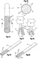
- abrasive pad 32 used as shown in Figure 1 on a conventional high speed machine (not shown).
- the machine is set at about 175 rpm's with a pad pressure of 0,41 - 2,07 N/mm 2 [60-300 psi].
- the cleaning can also be done by a drum brush 34 as shown in Figure 10 also mounted to a conventional drum machine (not shown).
- the pad 32 is made from a plurality of cleaning elements called strips or bristles 36 which can be in the form of a round, square or rectangular bristle as shown in Figure 2 which can be embedded with abrasive 38.
- the bristle 36 may be extruded from a high temperatures thermoplastic material mixed with abrasive particles 38.
- the abrasive particles 38 may be a hard particulate such as alumina silicate or small industrial diamond particles.
- the bristle 36 has a distal end 40 with an abrasive flat front face 39 that engages the polished floor 10 with the hardened abrasive particles.
- the abrasive particles are sufficiently aggressive to scour any dirt or grime that exists on the concrete floor.
- the square bristles are at least 3,175 mm [1/8 inch] wide to be larger than the pores of most normal concrete floors. While a square bristle is shown, rectangular or other shaped bristles are possible as long as they have a scrub face 39 over 3,175 mm [1/8 inch] wide.
- the bristle has its mounted end 42 embedded in the pad as shown in Figure 1 and 2 by being molded directly therein.
- the bristles are mounted such that the abrasive scrub face 39 is aligned transverse to the normal direction of motion of the pad at the face 39.
- the faces 39 are radially aligned about the center C of the pad when the pad rotates about its center C.
- the drum brush shown in Figure 10 has the faces 39 aligned along the width of the drum brush such that as the drum 34 rotates in the indicated direction, the face 39 flushly encounters the concrete floor.
- Figures 5 and 6 show where the extruded bristle is made such that only the distal area 40 has the diamond particulate embedded therein with the remaining or proximate section 42 being devoid of diamond particulate.
- the embedded diamonds extend completely through the interior of the bristle 36 as clearly illustrated in cross sectional view of Figure 6 .
- This embedded particulate has its advantages over the embodiment shown in Figures 3 and 4 as the bristle abrades through extended use, its outer surface at the distal end 40 no matter how worn always provides an outer abrasive surface 39 with diamond particulate 38 on a working surface.
- the distal end 40 abrades to provide a straight knife-like edge 41 on the concrete surface 12.
- the diamond particles 38 wear down and their effectiveness becomes diminished, they eventually abrade off the bristle as the substrate material whether plastic or steel also wears down to provide a fresh diamond particles just above to replenish the effectiveness of the bristle.
- an abrasive bristle maintains its abrasive aggressiveness for a long term.
- the resilient flexibility of the bristle provides relief when the pad hits a high spot of the concrete floor and will not gouge at the high spot or opens the pores at the high spot.
- the bristles 36 have a length that is sufficiently long compared to its thickness to provide resilient flexibility of the bristle as illustrated in Figure 2 to flex. As the bristle is shortened through the extended wear and the bristle becomes to short and too stiff for proper use, the diamond particulate also becomes exhausted which provides for a sensory indicator that the bush is worn out.
- the brush by having a bristle with a relatively wide, flat, and resilient flexible abrasive face 39 does not cause excessive deterioration of the concrete floor. In fact, it hones the concrete floor to maintain its smoothness.
- FIG. 7 and 8 A further embodiment is shown in Figures 7 and 8 which provides for a double ended bristle 46 that has two opposing distal ends 48 each with diamond particulate either coated or embedded in the same fashion as described in the embodiments shown and described for Figure 3-6 .
- both distal ends 48 are positioned to be operable against the floor surface 12.
- the mid-section 50 is mounted to the brush substrate by extending through holes 52 and being stapled in place by staple 54. Other molding techniques may also embed the mid-section 50 in the brush with the two distal ends 48 extending outward.
- the bristle provides for two cleaning sections with opposing abrasive faces 39. When the bristle is mounted into the pad, both faces 39 face the same direction.
- the operation of the brush bristles 46 is identical with the previous described embodiments.
- bristles 36 have a cross-section with a major and minor axis with the major axis being radially aligned about the center of rotation C and transverse to the normal motion of pad 32.
- the blade shaped bristles 36 while shown in four staggered sections can have a variety of configurations on pad 32.
- the bristles 36 may also have an elliptical or oblong cross-sectional shape with the major axis in the same position as shown.
- a bristle with a circular cross-section is also usable for honing the concrete surface if the diameter exceeds 3,175 mm [1/8"].
- the substrate may be made from steel such as steel wire or wire strips 36 as shown in Figure 11 with diamond particles 38 brazed or electroplated thereon (not according to the invention).
- FIG. 10 Another embodiment is shown in Figure 10 with drum 34 mounting wide blades 36 about its periphery to provide scrub faces 39 to operate in similar fashion as described before.
- the brush may also be used as an aggressive abrader. For this use, narrower bristles may also be used.
- an abrasive brush 110 for use on a conventional high speed power sanding machine has a base 112 that has conventional quick connect fittings 114 in the form of apertures which removably snap fit onto conventional studs (not shown) on the sander.
- the base which can be made from a plastic material mounts a proximate end 118 of a plurality of bristles 116 extending from the base 112.
- the bristles 16 may be arranged in a generally vertical direction as shown in Figure 13 .
- the bristles extend downwardly at differing angles. Whatever the angle, each bristle preferably has its distal end 120 generally or nearly coplanar with the other distal ends as more clearly shown in Figure 14 .
- the bristle 116 is shown to have a plurality of diamond particles 122 brazed or otherwise secured onto the surface of the bristle from its distal end and extending at least halfway up the distal end, i.e. about one quarter of the length of each bristle.
- the diamond particles may extend along the entire length of the each bristle.
- gage of the bristle and flexibility desired for a specific sanding application the diamond particles need to extend up to the wear point i.e. useful length of the bristle before the bristle brush is replaced.
- the diamond grit may vary but it is foreseen that a grit of 70 is useful for many sanding applications for concrete floors. Other particulates may be substituted for the diamond particles, for example alumina silicate or silicon carbide.
- the bristle 116 preferably has a round cross section as shown in Figure 16 .
- the distal portion of the bristles has the brazed diamonds thereon. For example, if the bristle is 50,8 mm [2 inches] long, the distal 25,4 mm [one inch] has the diamonds with no diamonds or braze above the midpoint.
- Other variations are foreseen such as a substantial portion of the distal half being covered by diamond particles or a substantial portion of the entire length of the bristle may have diamonds brazed thereon.
- the bristles may be made from stainless or carbon steel having a diameter of less than one millimeter up to 3,175 mm [one-eighth inch].
- the diamonds of 70 grit may be in a brazing alloy nickel slurry and sprayed onto the bristle with the brazing then being set with the diamonds secured in place.
- the bristle surface has the diamond particles 122 secured thereon with bristles areas 123 interspersed without diamonds or brazing materials.
- the presence of interspersed areas 123 retain flexibility of the steel bristle. If the entire bristle was saturated with brazing alloy, the bristles would become too brittle for the concrete sanding application.
- the particles can be spot brazed such as in stripes spots, or spirals to maintain interspersed areas 123 of steel bristle with no alloy thereon. As shown in Figures 12 and 20 , only the front scrub surface may have abrasive thereon with brazing alloy.
- the bristle 116 when new has its distal end 120 sand the concrete surface. It is found that the sharp edges of the diamond particles is sufficiently aggressive to sand the concrete surface and remove paint or other previously applied materials. The concrete floor quickly achieves a scratched surface in accordance with the grit sized used. The bristles do not clog with paint or smear any previously applied material such as paint or oil.
- the metal brush as it scours over the concrete with a power machine to force a pad pressure of 0,41 - 2,07 N/mm 2 [60-300 P.S.I.] will gradually have its substrate wear away.
- the worn diamond particles 122 at the distal end will shed off the bristle to expose new sharp edges of other diamond particles 122 further up on the bristle. This wearing will continuously occur until sufficient amount of the bristle will wear away as shown in Figure 18 .
- the performance or aggressiveness of the bristles in Figure 18 near the end of its useful life remains quite high relative to the performance of the bristles shown in Figure 17 when the pad is new.
- the aggressiveness of the bristle pad remains high like a new pad.
- the needed flexibility of the bristles during sanding is retained by the flexible steel, metal or other substrate of the bristles.
- the flexible bristles allow the brush to reach low sections of an uneven floor without excessive removal from high sections.
- a bristle with a generally rectangular i.e. flat contour can be used as shown in Figure 19 .
- Other modifications are possible, for example a roller with radially extending bristles for use with a drum sanding machine is also foreseen.
- high temperature plastics that can withstand the temperatures developed by a high speed power floor sander may be substituted for the metal substrate.
- an aggressive abrader that can prepare concrete surfaces for application of a surface coating that can abrade at multiple times faster than previous known plugs and sanding pads.
- the flexible bristles can follow the contour of a wavy or uneven floor surface to adequately prepare low sections or valleys of the concrete surface. The low section can be reached and sanded without extra removal from the high sections of the concrete surface. Hence, an uneven floor surface can be prepared for a coating more expeditiously and evenly.
Landscapes
- Engineering & Computer Science (AREA)
- Mechanical Engineering (AREA)
- Brushes (AREA)
- Polishing Bodies And Polishing Tools (AREA)
- Cleaning Implements For Floors, Carpets, Furniture, Walls, And The Like (AREA)
Claims (8)
- Schleifreinigungsvorrichtung, umfassend:ein Gehäuse (32); undeine Vielzahl von Reinigungsstreifen (36), die eine vordere Schleiffläche (39) mit einem flachen Rand, einer Breite und einer Länge aufweisen;wobei die Reinigungsstreifen (36) ein Substrat und an der Oberfläche der Reinigungsstreifen (36) ein Schleifmittel aufweisen; undwobei die Länge der Reinigungsstreifen (36) wesentlich größer als ihre Dicke ist, um eine Flexibilität der Reinigungsstreifen (36) bereitzustellen;wobei die Reinigungsstreifen (36) derart an dem Gehäuse (32) angebracht sind, dass die vordere Schleiffläche (39) jedes Reinigungsstreifens (36) im Wesentlichen quer zu der Normalenrichtung der Bewegung des Gehäuses (32) ausgerichtet ist und von wenigstens einem benachbarten Reinigungsstreifen (36) weg weist;dadurch gekennzeichnet, dass das Substrat eine Kunststoffmatrix ist, wobei das Schleifmittel durch harte Schleifpartikel (38) gebildet ist, die in einem distalen Ende (40) des Substrats eingebettet sind, wobei ein proximaler Befestigungsabschnitt (42) des Reinigungsstreifens (36) frei von Schleifmittel ist; undwobei der Reinigungsstreifen (36) mit dem flachen Rand an dem distalen Ende (40) Schmutz und Rückstände abkratzen soll und im Gebrauch, während sich die Schleifpartikel (38) abnutzen, sich die Schleifpartikel (38) abreiben, während sich der Reinigungsstreifen (36) verkürzt, um neue Schleifpartikel (38) freizulegen.
- Schleifreinigungsvorrichtung nach Anspruch 1, dadurch gekennzeichnet, dass:die Kunststoffmatrix ein Hochtemperaturkunststoff ist.
- Schleifreinigungsvorrichtung nach Anspruch 1, dadurch gekennzeichnet, dass:das Gehäuse ein drehbares Druckstück (32) ist, das für eine Drehung um einen Mittelpunkt (C) ausgebildet ist;wobei die vorderen Schleifflächen (39) der Reinigungsstreifen (36) im Wesentlichen radial mit der Mitte (C) des Druckstücks (32) ausgerichtet sind.
- Schleifreinigungsvorrichtung nach Anspruch 1, dadurch gekennzeichnet, dass:das Gehäuse rohrförmig ist und für eine Drehung um seine Hauptachse ausgebildet ist;wobei sich die Reinigungsstreifen (36) radial von dem Gehäuse weg erstrecken, mit den vorderen Schleifflächen (39) gemeinsam mit der Hauptachse ausgerichtet.
- Schleifreinigungsvorrichtung nach Anspruch 1, dadurch gekennzeichnet, dass:
das Schleifmittel (38) nur an der Oberfläche der vorderen Schleiffläche (39) vorgesehen ist. - Verfahren zum Reinigen einer polierten Betonfläche, umfassend:Bewegen einer Vielzahl von Reinigungsstreifen (36), die jeweils eine vordere Schleiffläche (39) aufweisen, die im Wesentlichen quer zu der Bewegungsrichtung ausgerichtet ist und von wenigstens einem benachbarten Reinigungsstreifen (36) weg weist, wobei der Reinigungsstreifen (36) ein Substrat und ein Schleifmittel an der Oberfläche der Reinigungsstreifen (36) aufweist, wobei das Substrat eine Kunststoffmatrix ist, wobei das Schleifmittel durch harte Schleifpartikel (38) gebildet ist, die in einem distalen Ende (40) des Substrats eingebettet sind, wobei ein proximaler Befestigungsabschnitt (42) des Reinigungsstreifens (36) frei von Schleifmittel ist;wobei sich die Reinigungsstreifen (36) biegen, um sich an hohe und niedrige Stellen der Betonfläche anzupassen; undwobei die Reinigungsstreifen (36) an dem distalen Ende (40) jeweils einen flachen Rand aufweisen, um Schmutz und Rückstände abzukratzen, und während sich die Schleifpartikel (38) abnutzen, sich die Schleifpartikel (38) abreiben, während sich der Reinigungsstreifen (36) verkürzt, um neue Schleifpartikel (38) freizulegen.
- Verfahren nach Anspruch 6, wobei:
die Reinigungsstreifen (36) eine Scheuerarbeitsfläche einer Schleifreinigungsvorrichtung bilden, wobei die Fläche im Wesentlichen flach ist und im Wesentlichen quer zu der Normalenrichtung der Bewegung der Reinigungsvorrichtung verläuft. - Verfahren nach Anspruch 7, wobei:
die Schleifpartikel (38) nur an der Scheuerarbeitsfläche befestigt sind.
Applications Claiming Priority (3)
| Application Number | Priority Date | Filing Date | Title |
|---|---|---|---|
| US10/851,393 US20050260940A1 (en) | 2004-05-21 | 2004-05-21 | Abrasive cleaning device |
| US11/042,698 US7081047B2 (en) | 2004-05-21 | 2005-01-25 | Bristle brush for concrete sanding |
| PCT/US2005/017849 WO2005113198A2 (en) | 2004-05-21 | 2005-05-20 | Abrasive cleaning device |
Publications (3)
| Publication Number | Publication Date |
|---|---|
| EP1755828A2 EP1755828A2 (de) | 2007-02-28 |
| EP1755828A4 EP1755828A4 (de) | 2009-11-25 |
| EP1755828B1 true EP1755828B1 (de) | 2019-01-16 |
Family
ID=35428885
Family Applications (1)
| Application Number | Title | Priority Date | Filing Date |
|---|---|---|---|
| EP05752053.8A Expired - Lifetime EP1755828B1 (de) | 2004-05-21 | 2005-05-20 | Schleifreiniger |
Country Status (3)
| Country | Link |
|---|---|
| US (1) | US7081047B2 (de) |
| EP (1) | EP1755828B1 (de) |
| WO (1) | WO2005113198A2 (de) |
Families Citing this family (15)
| Publication number | Priority date | Publication date | Assignee | Title |
|---|---|---|---|---|
| US8105134B2 (en) * | 2005-01-25 | 2012-01-31 | Epoxi Tech, Inc. | Low pressure polishing method and apparatus |
| US7988539B2 (en) * | 2004-05-21 | 2011-08-02 | Epoxi-Tech, Inc. | Abrasive cleaning device |
| US20050260940A1 (en) * | 2004-05-21 | 2005-11-24 | Simon Palushaj | Abrasive cleaning device |
| US20070272223A1 (en) * | 2006-05-24 | 2007-11-29 | Jeffrey Stuckey | Method for maintaining a polished concrete floor |
| US7690970B2 (en) * | 2007-01-19 | 2010-04-06 | Epoxy-Tech, Inc. | Abrasive preparation device with an improved abrasion element assembly |
| USD632537S1 (en) * | 2009-04-20 | 2011-02-15 | Epoxi Tech, Inc. | Abrasive blade |
| US9194189B2 (en) | 2011-09-19 | 2015-11-24 | Baker Hughes Incorporated | Methods of forming a cutting element for an earth-boring tool, a related cutting element, and an earth-boring tool including such a cutting element |
| WO2014122968A1 (ja) * | 2013-02-05 | 2014-08-14 | 新東工業株式会社 | ブラシユニットおよびこのブラシユニットを備えたブラシ研磨装置、ブラシ研磨システム、およびブラシ研磨方法 |
| DE112014004192T5 (de) * | 2013-09-13 | 2016-05-25 | Taimei Chemicals Co., Ltd | Polierverfahren, bürstenförmiger Schleifstein, Polierbürste und Drahtbündelung |
| US20170113327A1 (en) * | 2015-10-25 | 2017-04-27 | Dimar Ltd | Sanding device |
| CN106142103B (zh) * | 2016-08-26 | 2018-08-03 | 绵阳钢猫科技有限公司 | 智能清库除垢机器人 |
| FR3068714B1 (fr) * | 2017-07-10 | 2020-12-25 | Michelin & Cie | Procede de rodage de piste d’essai en enrobe bitumineux |
| CN109524331B (zh) * | 2018-11-26 | 2021-04-20 | 西安交通大学 | 一种用于硅绒面尖角及棱边圆滑化处理的楔形毛刷 |
| CN114728403B (zh) | 2019-08-19 | 2025-05-09 | 迪亚玛布鲁什有限公司 | 地面抛光装置 |
| CH720146A1 (de) | 2022-10-20 | 2024-04-30 | Romeo Buergisser | Verfahren und Verwendung einer Bürste zur Erhöhung der Trittsicherheit von Bodenbelägen |
Citations (1)
| Publication number | Priority date | Publication date | Assignee | Title |
|---|---|---|---|---|
| EP1120198A2 (de) * | 2000-01-28 | 2001-08-01 | Werner Blättler | Schleifwerkzeug, Bearbeitungsmaschine mit Schleifwerkzeug und Verfahren zum Bearbeiten von Werkstücken mittels Schleifwerkzeug |
Family Cites Families (21)
| Publication number | Priority date | Publication date | Assignee | Title |
|---|---|---|---|---|
| US3696563A (en) * | 1969-10-13 | 1972-10-10 | Rands Steve Albert | Abrasive brush having bristles with fused abrasive globules |
| GB1262020A (en) | 1970-07-28 | 1972-02-02 | Nypel Inc | Apparatus and method for making bristles having a filler |
| US4561214A (en) * | 1978-10-12 | 1985-12-31 | Inoue-Japax Research Incorporated | Abrading tool |
| US4493126A (en) * | 1982-01-11 | 1985-01-15 | Uy William C | Scraping brush |
| US4662044A (en) * | 1982-09-04 | 1987-05-05 | Tohken Co., Ltd. | Descaler and wire brush for use in the same |
| US4507361A (en) * | 1983-07-18 | 1985-03-26 | Allied Corporation | Low moisture absorption bristle of nylon and polyester |
| US4490872A (en) * | 1983-11-20 | 1985-01-01 | Drumm Arthur E | Spiral brush section |
| CA2033371A1 (en) * | 1990-12-28 | 1992-06-29 | Ernesto Nacar | Powerbrush attachment |
| US5445438A (en) * | 1991-10-17 | 1995-08-29 | Drumm; Arthur E. | Strip brush for mounting on a rotary drum |
| DE9202250U1 (de) * | 1992-02-21 | 1992-04-23 | Monti-Werkzeuge GmbH, 5300 Bonn | Rotativ antreibbares Bürstenaggregat |
| TW307801B (de) * | 1992-03-19 | 1997-06-11 | Minnesota Mining & Mfg | |
| US5679067A (en) * | 1995-04-28 | 1997-10-21 | Minnesota Mining And Manufacturing Company | Molded abrasive brush |
| US6352471B1 (en) * | 1995-11-16 | 2002-03-05 | 3M Innovative Properties Company | Abrasive brush with filaments having plastic abrasive particles therein |
| US5903951A (en) * | 1995-11-16 | 1999-05-18 | Minnesota Mining And Manufacturing Company | Molded brush segment |
| US5983434A (en) * | 1997-07-15 | 1999-11-16 | Minnesota Mining And Manufacturing Company | Rotary bristle tool with preferentially oriented bristles |
| US6190769B1 (en) * | 1999-02-19 | 2001-02-20 | E. I. Du Pont De Nemours And Company | Abrasive filaments of plasticized polyamides |
| US6422932B1 (en) * | 1999-10-15 | 2002-07-23 | 3M Innovative Properties Company | Integrally molded brush and method for making the same |
| US6665902B1 (en) * | 2000-04-20 | 2003-12-23 | United Rotary Brush Corporation | Metallic wire strip brush assembly and apparatus and method for making |
| JP4554064B2 (ja) * | 2000-12-19 | 2010-09-29 | 優一郎 新崎 | 線状のブラシ用素材 |
| US20020148059A1 (en) * | 2001-04-17 | 2002-10-17 | Shin-Cheng Lin | Descaling brush with particles of high hardness and rigidity and methods for manufacture |
| EP1260316B1 (de) * | 2001-04-25 | 2007-06-13 | Asahi Glass Company Ltd. | Polierverfahren |
-
2005
- 2005-01-25 US US11/042,698 patent/US7081047B2/en not_active Expired - Lifetime
- 2005-05-20 WO PCT/US2005/017849 patent/WO2005113198A2/en not_active Ceased
- 2005-05-20 EP EP05752053.8A patent/EP1755828B1/de not_active Expired - Lifetime
Patent Citations (1)
| Publication number | Priority date | Publication date | Assignee | Title |
|---|---|---|---|---|
| EP1120198A2 (de) * | 2000-01-28 | 2001-08-01 | Werner Blättler | Schleifwerkzeug, Bearbeitungsmaschine mit Schleifwerkzeug und Verfahren zum Bearbeiten von Werkstücken mittels Schleifwerkzeug |
Also Published As
| Publication number | Publication date |
|---|---|
| US7081047B2 (en) | 2006-07-25 |
| EP1755828A2 (de) | 2007-02-28 |
| US20050260941A1 (en) | 2005-11-24 |
| EP1755828A4 (de) | 2009-11-25 |
| WO2005113198A3 (en) | 2006-05-18 |
| WO2005113198A2 (en) | 2005-12-01 |
Similar Documents
| Publication | Publication Date | Title |
|---|---|---|
| US7988539B2 (en) | Abrasive cleaning device | |
| US20050260940A1 (en) | Abrasive cleaning device | |
| US8043144B2 (en) | Abrasive preparation device with an improved abrasion element assembly | |
| EP1755828B1 (de) | Schleifreiniger | |
| US8105134B2 (en) | Low pressure polishing method and apparatus | |
| EP0449509B1 (de) | Marmor-, Granit- und Steinenbearbeitungsverfahren und Schleifpolster hierfür | |
| WO2013181582A1 (en) | Diamond impregnated polishing pad with diamond pucks | |
| EP1603427B1 (de) | Schmirgelbürstenelemente und -bestandteile | |
| GB2263911A (en) | Abrasive tools | |
| US20070099549A1 (en) | Abrasive cleaning and honing device and method of honing concrete surfaces | |
| CN114728403A (zh) | 地面抛光装置 | |
| US2605592A (en) | Contact wheel, mainly for finishing belts | |
| CN114728402B (zh) | 在旋转研磨或抛光工具中使用的研磨元件 | |
| JPS61142078A (ja) | 研摩装置 | |
| KR102863025B1 (ko) | 그라인더의 연마장치 | |
| WO2025054053A1 (en) | Floor treatment assembly for floor surface machine | |
| US20070178817A1 (en) | Discontinuous abrasive particle releasing surfaces | |
| JP2007167353A (ja) | 洗浄研磨ブラシ | |
| JPH08150563A (ja) | 研磨ロールのドレッサー | |
| JPH055358U (ja) | 超硬砥粒を備えた弾性砥石 |
Legal Events
| Date | Code | Title | Description |
|---|---|---|---|
| PUAI | Public reference made under article 153(3) epc to a published international application that has entered the european phase |
Free format text: ORIGINAL CODE: 0009012 |
|
| 17P | Request for examination filed |
Effective date: 20061221 |
|
| AK | Designated contracting states |
Kind code of ref document: A2 Designated state(s): AT BE BG CH CY CZ DE DK EE ES FI FR GB GR HU IE IS IT LI LT LU MC NL PL PT RO SE SI SK TR |
|
| DAX | Request for extension of the european patent (deleted) | ||
| A4 | Supplementary search report drawn up and despatched |
Effective date: 20091028 |
|
| RIC1 | Information provided on ipc code assigned before grant |
Ipc: B24B 7/18 20060101ALI20091022BHEP Ipc: A46B 13/00 20060101ALI20091022BHEP Ipc: B24D 13/14 20060101AFI20091022BHEP |
|
| 17Q | First examination report despatched |
Effective date: 20130121 |
|
| GRAP | Despatch of communication of intention to grant a patent |
Free format text: ORIGINAL CODE: EPIDOSNIGR1 |
|
| STAA | Information on the status of an ep patent application or granted ep patent |
Free format text: STATUS: GRANT OF PATENT IS INTENDED |
|
| INTG | Intention to grant announced |
Effective date: 20180814 |
|
| GRAS | Grant fee paid |
Free format text: ORIGINAL CODE: EPIDOSNIGR3 |
|
| GRAA | (expected) grant |
Free format text: ORIGINAL CODE: 0009210 |
|
| STAA | Information on the status of an ep patent application or granted ep patent |
Free format text: STATUS: THE PATENT HAS BEEN GRANTED |
|
| REG | Reference to a national code |
Ref country code: DE Ref legal event code: R081 Ref document number: 602005055289 Country of ref document: DE Owner name: SIMIRON, INC., MADISON HEIGHTS, US Free format text: FORMER OWNER: EPOXI-TECH, INC., MADISON HEIGHTS, MICH., US Ref country code: DE Ref legal event code: R081 Ref document number: 602005055289 Country of ref document: DE Owner name: DIAMABRUSH LLC, MADISON HEIGHTS, US Free format text: FORMER OWNER: EPOXI-TECH, INC., MADISON HEIGHTS, MICH., US |
|
| AK | Designated contracting states |
Kind code of ref document: B1 Designated state(s): AT BE BG CH CY CZ DE DK EE ES FI FR GB GR HU IE IS IT LI LT LU MC NL PL PT RO SE SI SK TR |
|
| REG | Reference to a national code |
Ref country code: GB Ref legal event code: FG4D |
|
| REG | Reference to a national code |
Ref country code: CH Ref legal event code: EP |
|
| REG | Reference to a national code |
Ref country code: IE Ref legal event code: FG4D |
|
| REG | Reference to a national code |
Ref country code: DE Ref legal event code: R096 Ref document number: 602005055289 Country of ref document: DE |
|
| REG | Reference to a national code |
Ref country code: AT Ref legal event code: REF Ref document number: 1089362 Country of ref document: AT Kind code of ref document: T Effective date: 20190215 |
|
| REG | Reference to a national code |
Ref country code: DE Ref legal event code: R082 Ref document number: 602005055289 Country of ref document: DE Representative=s name: OPPERMANN, MARK, DIPL.-ING., DE Ref country code: DE Ref legal event code: R081 Ref document number: 602005055289 Country of ref document: DE Owner name: SIMIRON, INC., MADISON HEIGHTS, US Free format text: FORMER OWNER: EPOXI-TECH, INC., MADISON HEIGHTS, MICH., US Ref country code: DE Ref legal event code: R081 Ref document number: 602005055289 Country of ref document: DE Owner name: DIAMABRUSH LLC, MADISON HEIGHTS, US Free format text: FORMER OWNER: EPOXI-TECH, INC., MADISON HEIGHTS, MICH., US |
|
| RAP2 | Party data changed (patent owner data changed or rights of a patent transferred) |
Owner name: SIMIRON, INC. |
|
| REG | Reference to a national code |
Ref country code: NL Ref legal event code: MP Effective date: 20190116 |
|
| REG | Reference to a national code |
Ref country code: LT Ref legal event code: MG4D |
|
| PG25 | Lapsed in a contracting state [announced via postgrant information from national office to epo] |
Ref country code: NL Free format text: LAPSE BECAUSE OF FAILURE TO SUBMIT A TRANSLATION OF THE DESCRIPTION OR TO PAY THE FEE WITHIN THE PRESCRIBED TIME-LIMIT Effective date: 20190116 |
|
| REG | Reference to a national code |
Ref country code: AT Ref legal event code: MK05 Ref document number: 1089362 Country of ref document: AT Kind code of ref document: T Effective date: 20190116 |
|
| PG25 | Lapsed in a contracting state [announced via postgrant information from national office to epo] |
Ref country code: FI Free format text: LAPSE BECAUSE OF FAILURE TO SUBMIT A TRANSLATION OF THE DESCRIPTION OR TO PAY THE FEE WITHIN THE PRESCRIBED TIME-LIMIT Effective date: 20190116 Ref country code: LT Free format text: LAPSE BECAUSE OF FAILURE TO SUBMIT A TRANSLATION OF THE DESCRIPTION OR TO PAY THE FEE WITHIN THE PRESCRIBED TIME-LIMIT Effective date: 20190116 Ref country code: SE Free format text: LAPSE BECAUSE OF FAILURE TO SUBMIT A TRANSLATION OF THE DESCRIPTION OR TO PAY THE FEE WITHIN THE PRESCRIBED TIME-LIMIT Effective date: 20190116 Ref country code: PL Free format text: LAPSE BECAUSE OF FAILURE TO SUBMIT A TRANSLATION OF THE DESCRIPTION OR TO PAY THE FEE WITHIN THE PRESCRIBED TIME-LIMIT Effective date: 20190116 Ref country code: ES Free format text: LAPSE BECAUSE OF FAILURE TO SUBMIT A TRANSLATION OF THE DESCRIPTION OR TO PAY THE FEE WITHIN THE PRESCRIBED TIME-LIMIT Effective date: 20190116 Ref country code: PT Free format text: LAPSE BECAUSE OF FAILURE TO SUBMIT A TRANSLATION OF THE DESCRIPTION OR TO PAY THE FEE WITHIN THE PRESCRIBED TIME-LIMIT Effective date: 20190516 |
|
| PG25 | Lapsed in a contracting state [announced via postgrant information from national office to epo] |
Ref country code: GR Free format text: LAPSE BECAUSE OF FAILURE TO SUBMIT A TRANSLATION OF THE DESCRIPTION OR TO PAY THE FEE WITHIN THE PRESCRIBED TIME-LIMIT Effective date: 20190417 Ref country code: BG Free format text: LAPSE BECAUSE OF FAILURE TO SUBMIT A TRANSLATION OF THE DESCRIPTION OR TO PAY THE FEE WITHIN THE PRESCRIBED TIME-LIMIT Effective date: 20190416 Ref country code: IS Free format text: LAPSE BECAUSE OF FAILURE TO SUBMIT A TRANSLATION OF THE DESCRIPTION OR TO PAY THE FEE WITHIN THE PRESCRIBED TIME-LIMIT Effective date: 20190516 |
|
| REG | Reference to a national code |
Ref country code: DE Ref legal event code: R097 Ref document number: 602005055289 Country of ref document: DE |
|
| PG25 | Lapsed in a contracting state [announced via postgrant information from national office to epo] |
Ref country code: DK Free format text: LAPSE BECAUSE OF FAILURE TO SUBMIT A TRANSLATION OF THE DESCRIPTION OR TO PAY THE FEE WITHIN THE PRESCRIBED TIME-LIMIT Effective date: 20190116 Ref country code: AT Free format text: LAPSE BECAUSE OF FAILURE TO SUBMIT A TRANSLATION OF THE DESCRIPTION OR TO PAY THE FEE WITHIN THE PRESCRIBED TIME-LIMIT Effective date: 20190116 Ref country code: SK Free format text: LAPSE BECAUSE OF FAILURE TO SUBMIT A TRANSLATION OF THE DESCRIPTION OR TO PAY THE FEE WITHIN THE PRESCRIBED TIME-LIMIT Effective date: 20190116 Ref country code: EE Free format text: LAPSE BECAUSE OF FAILURE TO SUBMIT A TRANSLATION OF THE DESCRIPTION OR TO PAY THE FEE WITHIN THE PRESCRIBED TIME-LIMIT Effective date: 20190116 Ref country code: CZ Free format text: LAPSE BECAUSE OF FAILURE TO SUBMIT A TRANSLATION OF THE DESCRIPTION OR TO PAY THE FEE WITHIN THE PRESCRIBED TIME-LIMIT Effective date: 20190116 Ref country code: RO Free format text: LAPSE BECAUSE OF FAILURE TO SUBMIT A TRANSLATION OF THE DESCRIPTION OR TO PAY THE FEE WITHIN THE PRESCRIBED TIME-LIMIT Effective date: 20190116 |
|
| PLBE | No opposition filed within time limit |
Free format text: ORIGINAL CODE: 0009261 |
|
| STAA | Information on the status of an ep patent application or granted ep patent |
Free format text: STATUS: NO OPPOSITION FILED WITHIN TIME LIMIT |
|
| 26N | No opposition filed |
Effective date: 20191017 |
|
| REG | Reference to a national code |
Ref country code: CH Ref legal event code: PL |
|
| PG25 | Lapsed in a contracting state [announced via postgrant information from national office to epo] |
Ref country code: MC Free format text: LAPSE BECAUSE OF FAILURE TO SUBMIT A TRANSLATION OF THE DESCRIPTION OR TO PAY THE FEE WITHIN THE PRESCRIBED TIME-LIMIT Effective date: 20190116 Ref country code: LI Free format text: LAPSE BECAUSE OF NON-PAYMENT OF DUE FEES Effective date: 20190531 Ref country code: CH Free format text: LAPSE BECAUSE OF NON-PAYMENT OF DUE FEES Effective date: 20190531 |
|
| REG | Reference to a national code |
Ref country code: BE Ref legal event code: MM Effective date: 20190531 |
|
| PG25 | Lapsed in a contracting state [announced via postgrant information from national office to epo] |
Ref country code: LU Free format text: LAPSE BECAUSE OF NON-PAYMENT OF DUE FEES Effective date: 20190520 Ref country code: SI Free format text: LAPSE BECAUSE OF FAILURE TO SUBMIT A TRANSLATION OF THE DESCRIPTION OR TO PAY THE FEE WITHIN THE PRESCRIBED TIME-LIMIT Effective date: 20190116 |
|
| PG25 | Lapsed in a contracting state [announced via postgrant information from national office to epo] |
Ref country code: TR Free format text: LAPSE BECAUSE OF FAILURE TO SUBMIT A TRANSLATION OF THE DESCRIPTION OR TO PAY THE FEE WITHIN THE PRESCRIBED TIME-LIMIT Effective date: 20190116 |
|
| PG25 | Lapsed in a contracting state [announced via postgrant information from national office to epo] |
Ref country code: IE Free format text: LAPSE BECAUSE OF NON-PAYMENT OF DUE FEES Effective date: 20190520 |
|
| PG25 | Lapsed in a contracting state [announced via postgrant information from national office to epo] |
Ref country code: BE Free format text: LAPSE BECAUSE OF NON-PAYMENT OF DUE FEES Effective date: 20190531 |
|
| REG | Reference to a national code |
Ref country code: DE Ref legal event code: R082 Ref document number: 602005055289 Country of ref document: DE Representative=s name: OPPERMANN, MARK, DIPL.-ING., DE Ref country code: DE Ref legal event code: R081 Ref document number: 602005055289 Country of ref document: DE Owner name: DIAMABRUSH LLC, MADISON HEIGHTS, US Free format text: FORMER OWNER: SIMIRON, INC., MADISON HEIGHTS, MI, US |
|
| REG | Reference to a national code |
Ref country code: GB Ref legal event code: 732E Free format text: REGISTERED BETWEEN 20201015 AND 20201021 |
|
| PG25 | Lapsed in a contracting state [announced via postgrant information from national office to epo] |
Ref country code: CY Free format text: LAPSE BECAUSE OF FAILURE TO SUBMIT A TRANSLATION OF THE DESCRIPTION OR TO PAY THE FEE WITHIN THE PRESCRIBED TIME-LIMIT Effective date: 20190116 |
|
| PG25 | Lapsed in a contracting state [announced via postgrant information from national office to epo] |
Ref country code: HU Free format text: LAPSE BECAUSE OF FAILURE TO SUBMIT A TRANSLATION OF THE DESCRIPTION OR TO PAY THE FEE WITHIN THE PRESCRIBED TIME-LIMIT; INVALID AB INITIO Effective date: 20050520 |
|
| P01 | Opt-out of the competence of the unified patent court (upc) registered |
Effective date: 20230609 |
|
| PGFP | Annual fee paid to national office [announced via postgrant information from national office to epo] |
Ref country code: GB Payment date: 20240527 Year of fee payment: 20 |
|
| PGFP | Annual fee paid to national office [announced via postgrant information from national office to epo] |
Ref country code: DE Payment date: 20240530 Year of fee payment: 20 |
|
| PGFP | Annual fee paid to national office [announced via postgrant information from national office to epo] |
Ref country code: FR Payment date: 20240527 Year of fee payment: 20 |
|
| PGFP | Annual fee paid to national office [announced via postgrant information from national office to epo] |
Ref country code: IT Payment date: 20240521 Year of fee payment: 20 |
|
| REG | Reference to a national code |
Ref country code: DE Ref legal event code: R071 Ref document number: 602005055289 Country of ref document: DE |
|
| REG | Reference to a national code |
Ref country code: GB Ref legal event code: PE20 Expiry date: 20250519 |
|
| PG25 | Lapsed in a contracting state [announced via postgrant information from national office to epo] |
Ref country code: GB Free format text: LAPSE BECAUSE OF EXPIRATION OF PROTECTION Effective date: 20250519 |