EP1759663A2 - Procédés et appareil de remodelage de tissu mou corporel - Google Patents
Procédés et appareil de remodelage de tissu mou corporel Download PDFInfo
- Publication number
- EP1759663A2 EP1759663A2 EP06016818A EP06016818A EP1759663A2 EP 1759663 A2 EP1759663 A2 EP 1759663A2 EP 06016818 A EP06016818 A EP 06016818A EP 06016818 A EP06016818 A EP 06016818A EP 1759663 A2 EP1759663 A2 EP 1759663A2
- Authority
- EP
- European Patent Office
- Prior art keywords
- screw
- linking
- structures
- tissue
- collar
- Prior art date
- Legal status (The legal status is an assumption and is not a legal conclusion. Google has not performed a legal analysis and makes no representation as to the accuracy of the status listed.)
- Granted
Links
Images


Classifications
-
- A—HUMAN NECESSITIES
- A61—MEDICAL OR VETERINARY SCIENCE; HYGIENE
- A61F—FILTERS IMPLANTABLE INTO BLOOD VESSELS; PROSTHESES; DEVICES PROVIDING PATENCY TO, OR PREVENTING COLLAPSING OF, TUBULAR STRUCTURES OF THE BODY, e.g. STENTS; ORTHOPAEDIC, NURSING OR CONTRACEPTIVE DEVICES; FOMENTATION; TREATMENT OR PROTECTION OF EYES OR EARS; BANDAGES, DRESSINGS OR ABSORBENT PADS; FIRST-AID KITS
- A61F2/00—Filters implantable into blood vessels; Prostheses, i.e. artificial substitutes or replacements for parts of the body; Appliances for connecting them with the body; Devices providing patency to, or preventing collapsing of, tubular structures of the body, e.g. stents
- A61F2/02—Prostheses implantable into the body
- A61F2/24—Heart valves ; Vascular valves, e.g. venous valves; Heart implants, e.g. passive devices for improving the function of the native valve or the heart muscle; Transmyocardial revascularisation [TMR] devices; Valves implantable in the body
- A61F2/2442—Annuloplasty rings or inserts for correcting the valve shape; Implants for improving the function of a native heart valve
- A61F2/2451—Inserts in the coronary sinus for correcting the valve shape
-
- A—HUMAN NECESSITIES
- A61—MEDICAL OR VETERINARY SCIENCE; HYGIENE
- A61B—DIAGNOSIS; SURGERY; IDENTIFICATION
- A61B17/00—Surgical instruments, devices or methods
- A61B17/12—Surgical instruments, devices or methods for ligaturing or otherwise compressing tubular parts of the body, e.g. blood vessels or umbilical cord
- A61B17/128—Surgical instruments, devices or methods for ligaturing or otherwise compressing tubular parts of the body, e.g. blood vessels or umbilical cord for applying or removing clamps or clips
- A61B17/1285—Surgical instruments, devices or methods for ligaturing or otherwise compressing tubular parts of the body, e.g. blood vessels or umbilical cord for applying or removing clamps or clips for minimally invasive surgery
-
- A—HUMAN NECESSITIES
- A61—MEDICAL OR VETERINARY SCIENCE; HYGIENE
- A61B—DIAGNOSIS; SURGERY; IDENTIFICATION
- A61B17/00—Surgical instruments, devices or methods
- A61B17/04—Surgical instruments, devices or methods for suturing wounds; Holders or packages for needles or suture materials
- A61B17/0401—Suture anchors, buttons or pledgets, i.e. means for attaching sutures to bone, cartilage or soft tissue; Instruments for applying or removing suture anchors
- A61B2017/0409—Instruments for applying suture anchors
-
- A—HUMAN NECESSITIES
- A61—MEDICAL OR VETERINARY SCIENCE; HYGIENE
- A61B—DIAGNOSIS; SURGERY; IDENTIFICATION
- A61B17/00—Surgical instruments, devices or methods
- A61B17/04—Surgical instruments, devices or methods for suturing wounds; Holders or packages for needles or suture materials
- A61B17/0401—Suture anchors, buttons or pledgets, i.e. means for attaching sutures to bone, cartilage or soft tissue; Instruments for applying or removing suture anchors
- A61B2017/044—Suture anchors, buttons or pledgets, i.e. means for attaching sutures to bone, cartilage or soft tissue; Instruments for applying or removing suture anchors with a threaded shaft, e.g. screws
- A61B2017/0441—Suture anchors, buttons or pledgets, i.e. means for attaching sutures to bone, cartilage or soft tissue; Instruments for applying or removing suture anchors with a threaded shaft, e.g. screws the shaft being a rigid coil or spiral
-
- A—HUMAN NECESSITIES
- A61—MEDICAL OR VETERINARY SCIENCE; HYGIENE
- A61B—DIAGNOSIS; SURGERY; IDENTIFICATION
- A61B17/00—Surgical instruments, devices or methods
- A61B17/04—Surgical instruments, devices or methods for suturing wounds; Holders or packages for needles or suture materials
- A61B17/0487—Suture clamps, clips or locks, e.g. for replacing suture knots; Instruments for applying or removing suture clamps, clips or locks
- A61B2017/0488—Instruments for applying suture clamps, clips or locks
Definitions
- This invention relates to medical devices and methods. More particularly, the invention relates to prostheses that can be used for such purposes as remodeling soft body tissue structures of a patient, and to instruments and methods that can be used for implanting such prostheses in a patient.
- An example of a context in which this invention can be used is in a medical procedure that may be referred to as percutaneous mitral valve repair.
- Hindrichs et al. U.S. patent application 10/803,287, filed March 17, 2004 (and hereby incorporated by reference herein in its entirety) shows this type of procedure, and methods and apparatus for performing it.
- An embodiment of this type of procedure includes percutaneously implanting a first anchor structure in the coronary sinus of the patient (e.g., through the wall of the coronary sinus and into the myocardium below). Then a second anchor structure is percutaneously implanted in the right atrium of the patient outside the ostium of the coronary sinus.
- the distance between the two anchor structures is reduced by percutaneously tightening a linkage (e.g., of suture material) between those structures.
- a linkage e.g., of suture material
- the percutaneous mitral valve repair procedure mentioned in the preceding paragraphs is only one example of soft body tissue remodeling to which this type of technology may be applied.
- Other examples include (without limitation) (1) remodeling of a patient's left ventricle, (2) intra-atrial remodeling of a patient's mitral valve annulus, (3) intraventricular remodeling of a patient's mitral valve annulus, (4) remodeling of features of a patient's tricuspid valve, and (5) other cardiac applications. What is needed in many soft body tissue remodeling applications is long-term (chronic) durability of the prosthesis under dynamic loading of the prosthesis.
- An illustrative anchor structure for use in soft tissue remodeling includes first and second screw structures that can be driven into tissue a short distance apart along an axis along which the anchor structure will be pulled to remodel the tissue.
- the screw structures are driven into tissue transverse (e.g., substantially perpendicular) to this axis.
- a tether or linking member or structure e.g., of suture material or of suture-like material extends between head regions of the screw structures (and preferably also beyond the screw structures to the site of another more-distant anchor structure along the above-mentioned axis).
- a spacer member is located on the linking structure between the head regions of the screw structures.
- a cinching or clamping member or structure may optionally be disposed on the linking structure where it extends beyond the screw structures to snug the head regions of the screw structures and the spacer member together.
- aspects of the invention relate to (1) apparatus and methods for implanting an anchor structure of the general type described above, (2) apparatus and methods for implanting a second anchor structure of the general type described above, and (3) apparatus and methods for maintaining and/or shortening the distance between two anchor structures of the general type described above.
- Any or all aspects of the invention can be percutaneous, or surgical, or minimally invasive.
- the above-mentioned spacer between the screws may be adapted to promote tissue in-growth into and/or around the spacer member.
- screws of the type shown and described herein may be useful singly as anchor structures.
- the way in which the linking member is attached to a screw of the type shown herein, and other features of such a screw may give even a single screw of this type greater tissue holding power than other known single-screw-type anchor structures.
- one or both of the anchor structures mentioned in the preceding paragraphs may include only a single screw of the type shown herein and still be more effective than a prior, known, single-screw-type anchor structure.
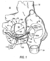
- FIG. 1 is a simplified, substantially horizontal (when the patient is standing), cross sectional view of a patient's heart showing illustrative treatment in accordance with the invention. (Another way to describe this cross section is as substantially parallel to the mitral valve annulus.)
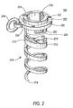
- FIG. 2 is a simplified perspective view of an illustrative embodiment of several representative components of an illustrative prosthesis in accordance with the invention.
- FIG. 3 is a simplified perspective view of an illustrative embodiment of a component of prosthesis delivery and implanting apparatus or instrumentation in accordance with the invention.
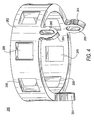
- FIG. 4 is a simplified perspective view of an illustrative embodiment of another component of prosthesis delivery and implanting apparatus in accordance with the invention.
- FIG. 5 is generally similar to FIG. 2, but with the components shown in FIGS. 3 and 4 added.
- FIG. 6 is a simplified perspective view of an illustrative embodiment of another representative component of an illustrative prosthesis in accordance with the invention.
- FIG. 7 is a simplified elevational view of an illustrative embodiment of representative components of an illustrative prosthesis, with illustrative apparatus for delivering and implanting one of those components, all in accordance with the invention.
- FIG. 8 is similar to FIG. 7, but shows a subsequent stage in use of what is shown in FIG. 7 in accordance with the invention.
- FIG. 9 is similar to FIG. 1, but shows an illustrative embodiment of some of the instrumentation that can be used in the implanting of a prosthesis in accordance with the invention.
- FIG. 10 is similar to FIG. 9, but shows a later stage in use of what is shown in FIG. 9 in accordance with the invention.
- FIGS. 9 and 10 show all heart structures the same size as FIG. 1. It will be understood, however, that in actual practice the annulus of a patient's mitral valve will typically be larger prior to implanting a prosthesis in accordance with this invention. In other words, in actual practice the mitral valve annulus will be larger in FIGS. 9 and 10 (prior to prosthesis implanting) than in FIG. 1 (after completion of the prosthesis implanting).)
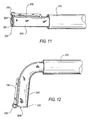
- FIG. 11 is a simplified elevational view of an illustrative embodiment of representative components of an illustrative prosthesis, with illustrative apparatus for delivering and implanting those components, all in accordance with the invention.
- FIG. 12 is similar to FIG. 11, but shows a subsequent stage in use of what is shown in FIG. 11.
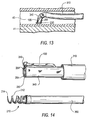
- FIG. 13 is a simplified sectional view of a portion of what is shown in FIGS. 1, 9, and 10 at a particular, relatively early stage in implanting a prosthesis in accordance with the invention.
- FIG. 14 is a simplified perspective view of an illustrative embodiment of representative components of an illustrative prosthesis, with illustrative apparatus for delivering and implanting those components, all in accordance with the invention.
- FIGS. 15-17 are similar to FIG. 13 for successive subsequent stages in implanting a prosthesis in accordance with the invention.
- FIG. 18 is generally similar to FIG. 14, but with certain components additionally assembled in accordance with the invention.
- FIGS. 19-23 are again similar to FIGS. 13 and 15-17, but show successive, more subsequent stages in implanting a prosthesis in accordance with the invention.
- FIG. 24 is a simplified cross sectional view of another portion of what is shown in FIGS. 1, 9, and 10 at a particular intermediate stage in implanting a prosthesis in accordance with the invention.
- FIGS. 25-32 are similar to FIG. 24, but show successive, more subsequent stages in implanting a prosthesis in accordance with the invention.
- FIG. 33 is a simplified cross section of an illustrative embodiment of certain components in accordance with the invention.
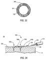
- FIG. 34 is similar to FIG. 32, but shows another illustrative embodiment of the invention.
- the invention will first be illustratively described primarily with reference to an embodiment for performing percutaneous mitral valve repair ("PMVR"). Later in this specification examples of possible alternatives to the first-described embodiment will be described, as will examples of some other possible uses of the invention.
- PMVR percutaneous mitral valve repair
- FIG. 1 left atrium 20, right atrium 30, superior vena cava 32, inferior vena cava 34, coronary sinus 40, ostium 42 of coronary sinus 40 (opening into right atrium 30), and mitral valve 50 (including anterior leaflet 52, posterior leaflet 54 (having three segments P1, P2, and P3), annulus 56, commissures 58a and 58b, and trigones 59a and 59b).
- mitral valve 50 including anterior leaflet 52, posterior leaflet 54 (having three segments P1, P2, and P3), annulus 56, commissures 58a and 58b, and trigones 59a and 59b.
- the anterior-posterior dimension of mitral valve 50 is labeled AP.
- FIG. 1 Heart 10 is shown in FIG. 1 with a prosthesis 100 implanted in it in accordance with certain aspects of the invention.
- Prosthesis 100 includes a first anchor structure 110 that has been implanted in coronary sinus 40 outside posterior mitral valve segment P2.
- Prosthesis 100 further includes a second anchor structure 120 that has been implanted in right atrium 30 outside the ostium 42 of coronary sinus 40.
- Prosthesis 100 still further includes a linking member 130 that extends between anchor structures 110 and 120, and that is tensioned to pull those anchor structures toward one another.
- a clamp 140 on linking member 130 just proximal to anchor structure 140 keeps anchor structures 110 and 120 at the desired spacing from one another along linking member 130.
- anchor structure 110 includes two screws 150a and 150b (only the head portions of these screws are actually visible in FIG. 1).
- the distal end of linking member 130 is secured to distal-most screw 150a at or adjacent the head of that screw.
- Spacer member 160a is disposed around linking member 130 immediately proximal to screw 150a.
- Linking member 130 passes through an eyelet (not visible in FIG. 1, but shown in later FIGS.) that is mounted on screw 150b adjacent its head.
- the length of spacer member 160a is approximately equal to the spacing of screws 150a and 150b along linking member 130. Spacer member 160a can be longer or shorter than is shown in FIG. 1 to provide a favorable angle to screws 150a and 150b.
- Anchor structure 120 also includes two screws 150c and 150d (again, only the heads being actually visible in FIG. 1).
- Linking member 130 passes through an eyelet (again, not visible in FIG. 1, but shown in later FIGS.) that is mounted on screw 150c adjacent its head.
- Proximal to the eyelet on screw 150c linking member 130 passes through another spacer member 160b, and then through an eyelet on screw 150d (similar to the eyelet on screw 150c).
- the length of spacer member 160b is approximately equal to the spacing of screws 150c and 150d along linking member 130.
- spacer member 160b can be longer or shorter than is shown in FIG. 1 to provide a favorable angle to screws 150c and 150d.
- Clamp structure 140 is mounted on linking member 130 immediately proximal to the above-mentioned eyelet on proximal-most screw 150d.
- Screws 150a and 150b have been driven through the wall of coronary sinus 40 into adjacent heart muscle tissue (preferably in the direction of mitral valve annulus 56, and even more preferably into tissue of that annulus). Screws 150c and 150d are driven into heart muscle tissue of right atrium 30.
- the above-mentioned Hindrichs et al. reference discusses in detail preferred locations of anchor structures like structures 110 and 120 (although the anchor structures shown herein are new in at least some respects).
- the Hindrichs et al. reference also discusses tissue structures that anchor structures like 110 and 120 preferably penetrate. All of these principles from the Hindrichs et al. reference are equally applicable to the present invention.
- FIG. 1 further shows that the two screws 150a and 150b that form part of anchor structure 110 are preferably spaced from one another approximately along the longitudinal axis of linking member 130. (This axis may sometimes be referred to herein as the tension axis of prosthesis 100.) The same is true for screws 150c and 150d.
- all of screws 150 are preferably driven into tissue transverse to the tension axis. For example, driving screws 150 approximately perpendicular to the tension axis is highly desirable but not a requirement for all embodiments of the invention, as long as the screws are transverse to the tension axis to a significant and meaningful degree.
- both screws 150 in each pair of screws tend to remain transverse to the tension axis.
- the screw 150b or 150c in each pair that is closer to the other pair may act through the associated spacer member 160a or 160b to brace or buttress the other screw 150a or 150d in that pair and thereby help the buttressed screw from becoming aligned with the tension axis.
- a screw that is driven into tissue and remains transverse to the tension axis provides much stronger holding of the tissue than a screw that can rotate into alignment with the tension axis.
- An anchor structure (e.g., 110 or 120) including two screws in accordance with this invention is more than twice as strong as a single-screw anchor structure of prior known construction. Moreover, this much stronger anchor structure can be delivered (e.g., percutaneously) through catheter apparatus that is no larger in diameter than would be required for delivery of a single-screw anchor structure of prior known construction.
- Screw 150 is actually an assembly of three components: threaded component 210, collar 230, and ring 240.
- Components 210, 230, and 240 may be made of any suitable bio-compatible material such as 316L stainless steel, L605, Elgiloy, MP35N, gold, platinum, platinum 10 iridium, platinum 20 iridium, titanium, Nitinol, tantalum, niobium, tungsten, Carpenter CCM, a polymer, another material coated with a polymer, etc.
- One or more of these components may have drug coating(s) and/or be drug eluting.
- one or more of the parts may be plated with a high atomic density material such as gold, platinum, tantalum, or the like.
- a high atomic density material such as gold, platinum, tantalum, or the like.
- One or more of the components may also be clad with one or more layers, such as stainless steel clad with tantalum metal.
- Threaded component 210 includes hollow, helical, corkscrew-like, screw portion 212 and hollow head portion 220.
- Screw portion 212 has a sharply pointed distal tip 214 to facilitate tissue penetration by the screw.
- Proximal of distal tip 214, screw portion 212 has several helical turns that lead back to head portion 220. These turns may include one or more barbs 216 to resist unthreading of the screw from tissue into which it has been threaded.
- each barb 216 is attached to screw portion 212 closer to distal tip 214 and is inclined out and away from the screw portion farther from the distal tip.
- each barb 216 is anticlinal from screw portion 212 in the direction opposite the direction in which the screw portion is driven into tissue.
- Head portion 220 is basically a hollow cylinder with a flange 222 extending radially outwardly from the proximal end of the cylinder. All portions of screw component 210 other than flange 222 are small enough to pass freely through collar 230. Flange 222 cannot pass through collar 230. Head portion 220 includes features that are usable to releasably hold screw component 210 on screw driving apparatus (not shown in FIG. 2, but detailed later in this specification). These features comprise three approximately T-shaped cut-outs or recesses 224 in head portion 220. These recesses are accessible from the hollow interior of head portion 220, and they are equidistantly spaced around the circumference of the head portion.
- Collar 230 fits loosely around the outside of head portion 220, but, as mentioned earlier, flange 222 is too large to pass through the collar. Accordingly, screw component 210 is rotatable about its longitudinal axis relative to collar 230, but when screw 150 is driven into tissue, collar 230 is trapped or captured on the screw by flange 222. Collar 230 includes features that are usable to releasably hold the collar on apparatus that is used to implant screw 150 in a patient. These features are recesses or apertures 232 in or through collar 230. Collar 230 also has a larger aperture 234 for loosely capturing ring 240.
- Ring 240 is large enough for linking member 130 to pass freely through the ring.
- ring 240 may be omitted from distal-most screw 150a so that the distal end of linking member 130 can be attached directly to aperture 232 on the collar 230 of that screw.
- linking member 130 preferably passes freely through the rings 240 on those screws.
- FIG. 3 shows a component of apparatus that can be used for releasably holding and driving a screw 150 of the type shown in FIG. 2.
- This screw holder/driver component 250 includes a hollow-cylindrical proximal portion 252 and three distally extending T-shaped portions 254.
- Proximal portion 252 includes a plurality of apertures 256 that are usable to help connect screw holder/driver 250 to apparatus components upstream from the holder/driver in a manner that facilitates transmission of torque from those upstream components to holder/driver 250.
- the component immediately upstream from holder/driver 250 is typically a torqueable flexible shaft (not shown in FIG. 3, but visible in FIG. 14).
- T-shaped portions 254 are shaped, sized, and located to fit somewhat loosely into the T-shaped cut-outs or recesses 224 in the head portion 220 of a screw 150. Although not shown in this condition in FIG. 3, T-shaped portions 254 are resiliently biased to deflect radially inwardly toward one another. When thus deflected radially inwardly, the enlarged, distal, free end parts of T-shaped portions 254 can pass freely into or out of the hollow cylindrical head 220 of a screw 150. However, T-shaped portions 254 can be deflected radially outwardly to the positions shown in FIG. 3 by inserting a properly sized cylindrical member (not shown in FIG. 3) into the interior of component 250.
- T-shaped portions 254 fit into T-shaped cut-outs or recesses 224 in the head portion of a screw 150. This both holds the screw to component 250 and allows the screw to be driven by rotating component 250.
- the above-mentioned cylindrical member can be withdrawn from the interior of holder/driven 250. This allows the enlarged distal ends of T-shaped fingers 254 to deflect inwardly and thereby exit from the corresponding portions of T-shaped recesses 224 in the screw. The screw is therefore no longer held on the apparatus by inter-engagement of elements 224 and 254.
- the particular structure shown and described above for releasably holding screw 150 on holder/driver 250 is only one example of many possible ways that this function can be achieved.
- features like 224 and 254 could have many other complementary shapes that would serve the purposes of releasably holding components 150 and 250 together and permitting the transmission of torque from component 250 to component 150 while those components are held together.
- the cylindrical member mentioned in the preceding paragraph may be used as a depth gauge for the driving of the associated screw. For example, when the distal end of this cylindrical member reaches the surface of the tissue, it is thereby known that the associated screw has been driven far enough into the tissue. Indeed, the structure may be arranged so that the tissue pushes the cylindrical member out of the screw, thereby decoupling the screw from its holder 250 and automatically stopping further driving of the screw at the proper depth of tissue penetration.
- FIG. 4 shows a component of apparatus that can be used to releasably hold a screw collar 230 of the type shown in FIG. 2.
- This collar holder 260 includes a hollow cylindrical proximal portion 262 and three distally extending gripper fingers 264.
- Proximal portion 262 can fit concentrically but loosely around the outside of holder/driver 250 (FIG. 3).
- Proximal portion 262 includes a plurality of apertures 266 that are usable to help connect collar holder 260 to upstream apparatus components. Fingers 264 fit into apertures 232 in collar 230. In the radial direction this fit is preferably loose. In the circumferential direction, however, this is a force fit, involving some resilient compression of the apertures 265 through fingers 264.
- a collar 230 can therefore be pressed onto holder 260, and it will thereafter remain on the holder. However, the collar can be pushed off the holder when the proximal surface of the threaded portion 210 associated with that collar is pushed distally with sufficient force.
- a separate catheter-like pusher could be used to push collar 230 off holder 260.
- FIG. 5 shows an assembly of the elements that are shown individually in FIGS. 2-4.
- Screw component 210 is releasably retained on holder/driver component 250 by the presence of T-shaped portions 254 of component 250 in complementary recesses 224 in the head portion 220 of screw portion 210.
- the presence of T-shaped portions 254 in recesses 224 also makes it possible to rotate screw component 210 about its longitudinal axis by rotating holder/driver component 250 about that axis.
- Collar 230 is releasably retained on collar holder 260 by the force-fitted presence of fingers 264 from holder 260 in collar apertures 232.
- Components 210 and 250 are rotatable relative to components 230 and 260 about the longitudinal axis of component 210.
- FIG. 1 shows an assembly of the elements that are shown individually in FIGS. 2-4.
- FIG. 6 shows an illustrative embodiment of a typical spacer member 160 in more detail.
- a spacer member 160 can be a hollow cylinder (e.g., of a bio-compatible metal).
- the hollow center of spacer member 160 is preferably large enough to allow the spacer member to slide freely along the length of linking member 130.
- the diameter of spacer member 160 should be large enough so that the ends of the spacer member can engage the head portions of screws 150 that the spacer member abuts.
- Spacer member 160 may have features beyond those shown in FIG. 6.
- spacer member 160 may have perforations, a dacron cover, and/or other features to promote tissue in-growth and anchoring in the patient.
- Suitable materials for spacer member 1.60 include those mentioned above for components 210, 230, and 240.
- clamp structure 140 Still another component of the apparatus is clamp structure 140.
- An illustrative embodiment of clamp structure 140 is shown in FIGS. 7 and 8, with some other apparatus also visible.
- clamp structure is disposed concentrically around a hollow tube 270 through which linking member 130 passes loosely.
- tube 270 has been removed to release clamping structure 140 to engage linking member 130. Note that the distal direction is to the left in FIGS. 7 and 8. This is consistent with FIG. 1.
- Clamp structure 140 (e.g., of bio-compatible metal) is resiliently biased to assume the shape shown in FIG. 8, but it can be elastically deflected to the shape shown in FIG. 7. (Alternatively clamping structure 140 could be plastically deformed from the shape shown in FIG. 7 to the shape shown in FIG. 8.) Proceeding from left to right in FIG. 7, clamp structure 140 includes (1) a hollow cylindrical portion 142, (2) a plurality of relatively short fingers 144 that extend in the proximal direction from cylindrical portion 142 and that are resiliently biased to deflect inwardly, and a (3) plurality of relatively long fingers 146 that also extend in the proximal direction from cylindrical portion 142 and that are intercalated with fingers 144.
- Proximal free end portions of fingers 146 are also resiliently biased to deflect inwardly.
- the inward bias of fingers 144 and 146 helps to hold clamp structure 140 on tube 270, albeit in such a way that tube 270 can be withdrawn from structure 140 when desired.
- the proximally directed free ends of fingers 144 are preferably sharp.enough to dig into linking member 130 when tube 270 is withdrawn from inside structure 140 (see FIG. 8). This prevents clamp structure 140 from moving proximally along linking member 130 once structure 140 has thus engaged member 130. This resistance to movement of structure 140 may be facilitated or enhanced by making linking member 130 of braided suture material as shown in FIGS. 7 and 8, but other constructions of linking member 130 are also possible, as will be further discussed later in this specification.
- proximally directed free ends of fingers 146 are less sharp and are intended to press inwardly on linking member 130 for such purposes as to stabilize clamp structure 140 on linking member and to prevent a braided linking member 130 from unraveling when it is subsequently cut proximal to clamp structure 140.
- An illustrative method begins with inserting an introducer tube 300 into the superior vena cava 32 of the patient as shown in FIG. 9. This may be done by starting from an introduction point into the patient along the patient's jugular vein. A possible alternative approach is via inferior vena cava 34. Either of these approaches gives access to right atrium 30. Although the distal end of introducer 300 is shown relatively low in FIG. 9, it may actually be higher and therefore out of sight in what is shown in that FIG.
- the next step in the illustrative method being discussed is to insert a guide catheter or sheath 310 into the patient via introducer 300 and to extend that guide catheter into the ostium 42 of coronary sinus 40 as is also shown in FIG. 9.
- the next step is to extend an obturator or dilator 320 and a wire 330 into guide catheter 310 and then from the distal end of the guide catheter farther into coronary sinus 40 (continue to see FIG. 9).
- Obturator 320 provides support for wire 330 to help the distal-most portion of the wire extend into coronary sinus 40, and possibly into a tributary thereof, well beyond the point at which the distal anchor structure 110 of prosthesis 100 will be implanted.
- the next step is to advance guide catheter 310 to the desired location of distal anchor structure 110. Obturator 320 is removed at this time.
- the next step is to introduce into guide catheter 310 and "over" wire 330 a delivery system for the first part of distal anchor structure 110.
- this is a delivery system for implanting screw 150a.
- FIG. 11 shows a first part of this delivery system extending from the distal end of guide catheter 310. For clarity, no tissue is shown in FIG. 11. This FIG also omits wire 330, although it will be understood that in actual use wire 330 may be present.
- the portion of the delivery system shown in FIG. 11 includes tubular member 340 extending from the distal end of guide catheter 310.
- a collar holder 260 (not visible in FIG.
- linking member 130 (which extends from a side lumen 341 of tubular member 340 (see FIG. 33)) is secured to ring 240 on collar 230.
- ring 240 could be omitted, and the distal end of linking member 130 could be secured directly to the aperture 234 in collar 230 that ring 240 is shown passing through.
- a proximal portion of linking structure 130 preferably passes along the side lumen 341 of tubular member 340 upstream from what is shown in FIG.
- Wire 330 (not shown in FIG. 11) can extend from the distal end of the assembly of elements 340/260/230 to its distal end to the left of what is shown in FIG. 11. Wire 330 can be withdrawn once the elements shown in FIG. 11 have reached the desired location along coronary sinus 40 (or the wire could be withdrawn earlier, e.g., after the distal end of guide catheter 310 has reached its desired location along coronary sinus 40 as shown in FIG. 10).
- the distal portion of tubular member 340 is "steerable" (see FIG. 12). This means that the distal portion of tubular member 340 can be controllably deflected transverse to the longitudinal axis of guide catheter 310 (or to the longitudinal axis of the proximally adjacent portion of tubular member 340). The amount of this deflection is preferably up to about 90° or more. In other words, the distal portion of tubular member 340 can be deflected so that it becomes substantially perpendicular to the proximally adjacent portion of that member. This allows the distal portion of tubular member 340 to be aimed at the side wall of coronary sinus 40 as shown in FIG. 13.
- tubular member 340 may be unidirectional, bidirectional, or multidirectional (in other words, in one direction transverse to the longitudinal axis of the remainder of the structure, in either of two directions transverse to that longitudinal axis, or in any one of several directions transverse to that longitudinal axis).
- the relative sizes and shapes of the tissue and apparatus components may be such that transverse deflection of the distal portion of the structure causes a substantial distortion of coronary sinus 40 at that location.
- the "back" side of the apparatus i.e., adjacent the bend in tubular member 340
- the same kind of distortion of coronary sinus 40 may occur in connection with FIG. 19, although this distortion is again not actually shown in that FIG.)
- FIG. 14 Further components of the delivery system for implanting screw 150a are shown in FIG. 14. These components include tubular member 350 with a screw holder/driver attached to its distal end and threaded component 210 held on that holder/driver. Another tube or plug (not visible) is disposed coaxially inside elements 350 and 250 to initially keep T-shaped portions 254 of holder/driver 250 deflected radially outward in the complementary recesses 224 in threaded component 210 and thereby hold threaded component 210 on holder/driver 250.
- tubular member 350 with a screw holder/driver attached to its distal end and threaded component 210 held on that holder/driver.
- Another tube or plug (not visible) is disposed coaxially inside elements 350 and 250 to initially keep T-shaped portions 254 of holder/driver 250 deflected radially outward in the complementary recesses 224 in threaded component 210 and thereby hold threaded component 210 on holder/driver 250.
- Components 350/250/210 are insertable coaxially into and along tubular member 340 from the proximal end of member 340. Components 350/250/210 may be inside member 340 when member 340 is inserted into guide catheter 310. When the distal portion of member 340 is properly aimed toward the side wall of coronary sinus 40 as shown in FIG. 13, tubular member 350 may be pushed distally and rotated about its longitudinal axis to cause threaded portion 210 to begin to emerge from the distal end of assembly 340/260/230 and to begin to threadedly penetrate the side wall of coronary sinus 40 and adjacent heart tissue 41 (see FIG. 15).
- components 310 and/or 340 preferably bear on the wall of coronary sinus 40 approximately opposite the tissue-entry point of threaded portion 210 to help force threaded portion 210 into the tissue.
- Component 350 is preferably sufficiently laterally flexile to follow the lateral (steering) deflection of component 340.
- Component 350 is also able to transmit to component 210 the torque necessary to thread component 210 into tissue.
- Screw 150a is now implanted in tissue 40/41 and fully released from delivery apparatus 340/260/350/250, although the screw is still attached to the distal end of linking member 130.
- the next step is to re-straighten the steerable distal portion of tubular member 340 and withdraw components 340, 360, 350, and 250 from the patient.
- the condition of the apparatus is now as shown in FIG. 16.
- the next step is to push spacer member 160a into the patient over linking member 130.
- a proximal portion of linking member 130 may transition from a suture-like material to a wire to facilitate getting spacer member 160a (and other apparatus) into the patient over linking member 130.
- a tubular pusher 370 may be placed over linking member 130 proximal to spacer member 160a for use in pushing spacer member 160a into the patient and into abutment with screw 150a as shown in FIG. 17.
- tubular pusher 370 may be withdrawn from the patient.
- the next step is to position the distal end of guide catheter 310 appropriately for implanting second screw 150b.
- Apparatus for delivering second screw 150b can then be inserted into the patient via guide catheter 310.
- the delivery system for second screw 150b can be very similar to the above-described delivery system for first screw 150a. The only significant difference is that in the case of second screw 150b linking member 130 passes loosely through the ring 240 of the second screw rather than being secured to the screw as in the case of first screw 150a.
- FIG. 18 illustrates this type of loose passage of linking member 130 through a ring 240 on a screw 150 like screw 150b.
- the delivery system for screw 150b can be so similar to the delivery system for screw 150a, the same reference numbers will be used again (but with a "b" suffix) for components of the second screw delivery system. Discussion of delivery and implanting of the second screw can also be somewhat abbreviated because it is so similar to the above-described delivery and implanting of the first screw.
- FIG. 19 shows the condition of the apparatus after components 340b, 260b, and 230b for second screw 150b have been extended from the distal end of guide catheter 310 and steered (i.e., laterally deflected) toward the desired point on the side wall of coronary sinus 40.
- the threaded portion 210b of second screw 150b can be advanced distally through assembly 340b/260b/230b and driven into tissue 40/41 as described above for the corresponding components associated with screw 150a (see FIG. 20).
- threaded portion 210b After threaded portion 210b has been driven into tissue 40/41, threaded portion 210b can be released from its holder/driver (not visible, but inside tubular member 340b) as described earlier for the corresponding parts associated with screw 150a. Then collar 230b can be released from its holder 260b in the same manner as described above for the corresponding parts associated with screw 150a. The distal end of tubular member 340b can be re-straightened, and all of the delivery apparatus for screw 150b can be proximally withdrawn from the patient via guide catheter 310. The condition of the apparatus is now as shown in FIG. 21.
- FIGS. 22 and 23 clamp structure 140a and associated delivery apparatus (e.g., as shown in more detail in FIG. 7) is loaded onto linking member 130 and introduced into the patient via guide catheter 310.
- the delivery apparatus for clamp 140a includes a tube 270 inside the clamp (see FIG. 7) and another tubular member 380 disposed concentrically around the outside of tube 270 and bearing (at its distal end) on the proximal end of the clamp.
- FIG. 22 shows clamp 140a pushed up against structure of screw 150b and therefore ready for release onto linking member 130.
- Clamp 140a is released onto linking member 130 by pulling back on tube 270 while holding tubular member 380 stationary (see also FIG. 8). Proximal withdrawal of tube 270 allows the various fingers 144 and 146 to engage member 130 as described earlier in connection with FIG. 8. Tubes 270 and 380 can then be completely withdrawn from the patient, leaving the apparatus as shown in FIG. 23.
- the presence of clamp 140a pressing distally on the structure of proximal screw 150b may help to stiffen and strengthen distal anchor structure 110 (including screws 150a and 150b and spacer 160a). However, use of clamp 160a is optional.
- the next step is to retract guide catheter 310 into the patient's right atrium 30 (see FIG. 24).
- the distal end of guide catheter 310 is placed near the desired location of third screw 150c.
- Delivery and implanting of third screw 150c can be similar (except for location) to delivery and implanting of second screw 150b. Accordingly, the description for third screw 150c can be somewhat abbreviated.
- FIG. 24 shows the apparatus after the distal end of the delivery system for third screw 150c has been steered (deflected laterally) toward the desired implant site for screw 150c in the tissue 31 of right atrium 30.
- Hindrichs et al. reference discusses preferred locations for a proximal tissue anchor.
- the proximal anchor placement principles discussed there are equally applicable to placing screw 150c in accordance with this invention. Those principles are preferably followed in locating and implanting screw 150c (and screw 150d) in practicing the present invention.
- delivery system components 340c and 260c for third screw 150c position the collar 230c for the third screw against the surface of heart tissue 31 at the desired location.
- Linking member 130 comes from above-described distal anchor 110 (out of sight to the left in FIG. 24), passes through the ring 240c on collar 230c, and enters tubular member 340c.
- tubular member 340c can be passive deflection (i.e., a shape that is remembered by member 340c once that member is out of guide catheter 310).
- pull wires may be needed to generate more deflecting force and deform the coronary sinus. But in right atrium 30 tissue deformation may not be involved, and so passive steering deflection of tubular member 340c may be sufficient. (The same may be true for tubular member 340d, described below.)
- the threaded portion 210c of that screw is driven (by other delivery system components that are inside components 340c and 260c and that are similar to components 350 and 250 (FIG. 14)) through collar 230c and into tissue 31 as shown in FIG. 25. Threaded portion 210c is then released from its holder/driver, collar 230c is released from its holder 260c, and the delivery system for screw 150c is re-straightened and withdrawn from the patient via guide catheter 310.
- the condition of the apparatus is now as shown in FIG. 26.
- the next step is to insert spacer 160b into the patient along linking member 130 until it abuts the proximal side of screw 150c. This step is so similar to the insertion of spacer 160a that it does not need to be separately illustrated or further described.
- the next step is to reposition the distal end of guide catheter 310 for implanting of fourth screw 150d. Then the fourth screw and its delivery system are inserted into guide catheter 310 over linking member 130. The distal end of the delivery system 340d for fourth screw 150d is then steered toward tissue 31 just proximal to screw 150c and spacer 160b as shown in FIG. 27. Again, this steering may be passive as in the case of delivery system 340c.
- the next step, illustrated by FIG. 28, is to drive the threaded portion 210d of screw 150d through collar 230d and into tissue 31. Thereafter, threaded portion 210d is released from its holder/driver apparatus (not visible, but similar to previously shown and described components of the same kind), and collar 230d is released from its holder 260d. Delivery system 340d is then re-straightened and withdrawn from the patient via guide catheter 310. The condition of the apparatus is now as shown in FIG. 29.
- the next step is to introduce a second clamp 140b into the patient on second clamp delivery apparatus 380b (see FIG. 30). This is again done via guide catheter 310 and with all of elements 380b and 140b around the portion of linking member 130 that is proximal to proximal anchor structure 120.
- linking structure 130 and structure 140b/380b can be used to shorten the distance between anchor structures 110 and 120 to any desired degree. This can be done by pulling proximally on the proximal end of linking structure 130 (outside of the patient) while pushing distally on components 140b/380b (also from outside the patient).
- the amount of spacing between distal and proximal anchor structures 110 and 120 is adjustable in both directions until clamp 140b is launched. This means that different spacings can be tried until the best spacing is found. Even if the spacing is initially decreased too much, that can be reversed by allowing the spacing to increase again. Clamp 140b is launched only after the best spacing has been found. It should also be noted that in this embodiment the spacing between anchor structures 110 and 120 is "infinitely adjustable" (within, of course, the practical range for such spacing). This means that within the practical range, the prosthesis can select and maintain any desired spacing between anchor structures 110 and 120.
- the preceding paragraph refers to the possibility of trying different spacings of anchor structures 110 and 120 until the best spacing is found.
- the best spacing may be judged with the aid of any of a number of techniques such as direct visualization, fluoroscopy, echo cardiography, computed tomography, MRI, hemodynamic monitoring techniques, etc.
- clamp 140b After clamp 140b has been launched, the next step is to cut linking structure 130 proximal to clamp 140b and to remove everything that is proximal to the cut.
- the condition of the apparatus is now as shown in FIG. 32 (and also FIG. 1). The process of implanting the prosthesis is complete and all delivery apparatus can be withdrawn from the patient.
- a possible variation on the above method is to install the prosthesis as described above with little or no significant shortening of the distance between anchor structures 110 and 120.
- the prosthesis acts as a precaution or prophylactic against possible future weakening and distension of the mitral valve annulus in the portion of that annulus that is spanned by the prosthesis.
- FIG. 34 Another possible variation on the above-described methods and apparatus is illustrated by FIG. 34.
- the prosthesis is implanted as described above (with or without shortening of the distance between anchor structures 110 and 120). Some of linking member 130 is left proximal to clamp 140b.
- the patient can be re-entered to change or further change the spacing between anchor structures 110 and 120.
- the reentry apparatus may include catheter 410, which can be introduced into the patient percutaneously in the same way that other apparatus described above can be introduced.
- Catheter 410 is used to deliver snare structure 420/430 into the patient adjacent to the proximal end of linking member 130.
- Snare loop 430 is deployed and snares the proximal end of linking member 130.
- Linking member 130 may have been left with a proximal enlargement 132 to facilitate good engagement by snare loop 430.
- Enlargement 132 may be radio-opaque to facilitate finding it in the patient.
- Snare loop 430 is used to hold the end of linking structure 130 while snare tube 420 is pushed distally onto linking structure 130.
- snare tube 420 When the distal end of snare tube 420 reaches clamp 160b, snare tube 420 can be used to push that clamp distally along linking member 130, while snare loop 430 is pulled proximally to hold linking member 130 in place. In this way the distance between anchor structures 110 and 120 can be shortened or further shortened at any time after the prosthesis has been implanted. When the desired shortening or further shortening has been achieved, linking member 130 can be released from snare loop 430 and apparatus 410/420/430 can be withdrawn from the patient. Clamp 140b will maintain the prosthesis with whatever spacing has been set between anchor structures 110 and 120.
- Embodiments of the type illustrated by FIG. 34 may be desirable because they can take advantage of the fact that anchor structures 110 and 120 tend to be stronger after the tissue in which they are implanted has healed.
- the prosthesis can be initially implanted with little or no shortening of the distance between anchor structures 110 and 120, and therefore with little or no tension in linking member 130. There is therefore little or no force acting on the anchor structures that might tend to pull them from the tissue. After the tissue has healed, the anchor structures are stronger than they are when first implanted. The technique and apparatus illustrated by FIG. 34 can then be used to tension linking member 130 and shorten the distance between anchor structures 110 and 120. Because the tissue at the anchor structures has already healed when this is done, the prosthesis is even more secure than it otherwise would have been.
- each screw 210 could be held on its holder 250 by structures 254 (FIG. 3) that are resiliently biased to deflect outwardly rather than inwardly as described above.
- Each ring 240 e.g., FIG. 2 could be integrated into the associated collar 230 rather than being a separate component.
- Each of anchor structures 110 and 120 could be on a separate linking member like 130, with both of those linking members pulled through a common final clamp (like 140b) to pull the two anchor structures together.
- the above-mentioned Hindrichs et al. reference shows this type of use of two strands pulled through a common final clamp.
- One or more of anchor structures 110 and 120 can be (or can include) a tissue-piercing lead for any type of electrical apparatus.
- Linking member 130 can be or can be part of an electrical conductor that is electrically connected to the tissue-piercing lead. This conductor can extend to other electrical apparatus inside and/or outside the patient.
- any portion or portions of the prosthesis can have one or more coatings for biological purposes such as to reduce inflammatory response, promote healing, reduce clotting or thrombogenicity response, etc. For example, this may be accomplished by using one or more polymer coatings that can elute one or more drugs or medications.
- Linking member 130 can have radio-opaque markers at predetermined spacings or locations to help visualize the amount of shortening between anchor structures 110 and 120 that is being achieved. Any of the materials and/or material constructions mentioned anywhere throughout this specification can be used for any component or components of the prosthesis, as is appropriate for that component or for those components.
- screw structures 150 of the types shown and described herein have features that may permit effective use of only one such screw (rather than a pair) as an anchor structure such as 110 and/or 120 in a prosthesis in accordance with this invention.
- collar 230 may act as a washer that bears on the surface of tissue and helps to reduce tipping of a single screw structure 150 when that structure is pulled on by the linking member 130 of a prosthesis.
- the fact that the point of attachment of linking member 130 to screw structure 150 is on collar 230 (which is at or close to the tissue surface rather than at the top of the screw structure) and off the central longitudinal axis of screw structure 150 may further help to reduce tipping of a single screw structure when pulled by the linking member.
Landscapes
- Health & Medical Sciences (AREA)
- Life Sciences & Earth Sciences (AREA)
- Cardiology (AREA)
- General Health & Medical Sciences (AREA)
- Veterinary Medicine (AREA)
- Biomedical Technology (AREA)
- Heart & Thoracic Surgery (AREA)
- Vascular Medicine (AREA)
- Engineering & Computer Science (AREA)
- Animal Behavior & Ethology (AREA)
- Surgery (AREA)
- Public Health (AREA)
- Transplantation (AREA)
- Reproductive Health (AREA)
- Nuclear Medicine, Radiotherapy & Molecular Imaging (AREA)
- Oral & Maxillofacial Surgery (AREA)
- Medical Informatics (AREA)
- Molecular Biology (AREA)
- Prostheses (AREA)
- Surgical Instruments (AREA)
Applications Claiming Priority (1)
| Application Number | Priority Date | Filing Date | Title |
|---|---|---|---|
| US11/215,341 US9492277B2 (en) | 2005-08-30 | 2005-08-30 | Soft body tissue remodeling methods and apparatus |
Publications (3)
| Publication Number | Publication Date |
|---|---|
| EP1759663A2 true EP1759663A2 (fr) | 2007-03-07 |
| EP1759663A3 EP1759663A3 (fr) | 2007-04-25 |
| EP1759663B1 EP1759663B1 (fr) | 2009-12-16 |
Family
ID=37433689
Family Applications (1)
| Application Number | Title | Priority Date | Filing Date |
|---|---|---|---|
| EP06016818A Not-in-force EP1759663B1 (fr) | 2005-08-30 | 2006-08-11 | Appareil de remodelage de tissu mou corporel |
Country Status (4)
| Country | Link |
|---|---|
| US (1) | US9492277B2 (fr) |
| EP (1) | EP1759663B1 (fr) |
| AT (1) | ATE451892T1 (fr) |
| DE (1) | DE602006011092D1 (fr) |
Cited By (20)
| Publication number | Priority date | Publication date | Assignee | Title |
|---|---|---|---|---|
| WO2012135045A1 (fr) * | 2011-03-25 | 2012-10-04 | Smith & Nephew, Inc. | Lifting des tissus |
| WO2013103796A1 (fr) * | 2012-01-05 | 2013-07-11 | Cook Medical Technologies Llc | Dispositif de fixation permettant d'approcher des tissus et leur retrait |
| WO2014108903A1 (fr) * | 2013-01-09 | 2014-07-17 | 4Tech Inc. | Organes d'ancrage de tissu mou |
| US8961594B2 (en) | 2012-05-31 | 2015-02-24 | 4Tech Inc. | Heart valve repair system |
| US8961596B2 (en) | 2010-01-22 | 2015-02-24 | 4Tech Inc. | Method and apparatus for tricuspid valve repair using tension |
| EP2525741A4 (fr) * | 2010-01-22 | 2015-05-06 | 4Tech Inc | Réparation de valve tricuspide à l'aide d'une tension |
| US9241702B2 (en) | 2010-01-22 | 2016-01-26 | 4Tech Inc. | Method and apparatus for tricuspid valve repair using tension |
| US9307980B2 (en) | 2010-01-22 | 2016-04-12 | 4Tech Inc. | Tricuspid valve repair using tension |
| US9801720B2 (en) | 2014-06-19 | 2017-10-31 | 4Tech Inc. | Cardiac tissue cinching |
| US9907547B2 (en) | 2014-12-02 | 2018-03-06 | 4Tech Inc. | Off-center tissue anchors |
| US9907681B2 (en) | 2013-03-14 | 2018-03-06 | 4Tech Inc. | Stent with tether interface |
| US10022114B2 (en) | 2013-10-30 | 2018-07-17 | 4Tech Inc. | Percutaneous tether locking |
| US10039643B2 (en) | 2013-10-30 | 2018-08-07 | 4Tech Inc. | Multiple anchoring-point tension system |
| US10052095B2 (en) | 2013-10-30 | 2018-08-21 | 4Tech Inc. | Multiple anchoring-point tension system |
| US10058323B2 (en) | 2010-01-22 | 2018-08-28 | 4 Tech Inc. | Tricuspid valve repair using tension |
| US10806579B2 (en) | 2017-10-20 | 2020-10-20 | Boston Scientific Scimed, Inc. | Heart valve repair implant for treating tricuspid regurgitation |
| WO2021026068A1 (fr) * | 2019-08-02 | 2021-02-11 | Boston Scientific Scimed, Inc. | Conceptions d'ancrage conçues en vue d'une commande de migration/retrait d'ancrage |
| WO2022172149A1 (fr) * | 2021-02-09 | 2022-08-18 | Edwards Lifesciences Innovation (Israel) Ltd. | Ancrages tissulaires et techniques pour leur utilisation |
| US11857417B2 (en) | 2020-08-16 | 2024-01-02 | Trilio Medical Ltd. | Leaflet support |
| EP4051182B1 (fr) * | 2019-10-29 | 2024-08-21 | Edwards Lifesciences Innovation (Israel) Ltd. | Technologies d'ancrage d'annuloplastie et de tissu |
Families Citing this family (171)
| Publication number | Priority date | Publication date | Assignee | Title |
|---|---|---|---|---|
| US7753922B2 (en) * | 2003-09-04 | 2010-07-13 | Guided Delivery Systems, Inc. | Devices and methods for cardiac annulus stabilization and treatment |
| US9949829B2 (en) | 2002-06-13 | 2018-04-24 | Ancora Heart, Inc. | Delivery devices and methods for heart valve repair |
| US7758637B2 (en) * | 2003-02-06 | 2010-07-20 | Guided Delivery Systems, Inc. | Delivery devices and methods for heart valve repair |
| EP1530441B1 (fr) * | 2002-06-13 | 2017-08-02 | Ancora Heart, Inc. | Dispositifs et procedes de reparation de valvule cardiaque |
| US20060122633A1 (en) * | 2002-06-13 | 2006-06-08 | John To | Methods and devices for termination |
| US7883538B2 (en) * | 2002-06-13 | 2011-02-08 | Guided Delivery Systems Inc. | Methods and devices for termination |
| US7753924B2 (en) | 2003-09-04 | 2010-07-13 | Guided Delivery Systems, Inc. | Delivery devices and methods for heart valve repair |
| US8287555B2 (en) * | 2003-02-06 | 2012-10-16 | Guided Delivery Systems, Inc. | Devices and methods for heart valve repair |
| US7753858B2 (en) * | 2002-06-13 | 2010-07-13 | Guided Delivery Systems, Inc. | Delivery devices and methods for heart valve repair |
| US20060241656A1 (en) * | 2002-06-13 | 2006-10-26 | Starksen Niel F | Delivery devices and methods for heart valve repair |
| US7666193B2 (en) | 2002-06-13 | 2010-02-23 | Guided Delivery Sytems, Inc. | Delivery devices and methods for heart valve repair |
| US8641727B2 (en) | 2002-06-13 | 2014-02-04 | Guided Delivery Systems, Inc. | Devices and methods for heart valve repair |
| US7588582B2 (en) * | 2002-06-13 | 2009-09-15 | Guided Delivery Systems Inc. | Methods for remodeling cardiac tissue |
| US7534204B2 (en) * | 2003-09-03 | 2009-05-19 | Guided Delivery Systems, Inc. | Cardiac visualization devices and methods |
| US20050273138A1 (en) * | 2003-12-19 | 2005-12-08 | Guided Delivery Systems, Inc. | Devices and methods for anchoring tissue |
| US7942927B2 (en) | 2004-03-15 | 2011-05-17 | Baker Medical Research Institute | Treating valve failure |
| US20080288060A1 (en) * | 2004-07-06 | 2008-11-20 | Baker Medical Research Institute | Treating Valvular Insufficiency |
| WO2006097931A2 (fr) | 2005-03-17 | 2006-09-21 | Valtech Cardio, Ltd. | Techniques de traitement de la valve mitrale |
| US8333777B2 (en) | 2005-04-22 | 2012-12-18 | Benvenue Medical, Inc. | Catheter-based tissue remodeling devices and methods |
| US8951285B2 (en) | 2005-07-05 | 2015-02-10 | Mitralign, Inc. | Tissue anchor, anchoring system and methods of using the same |
| US20070118151A1 (en) * | 2005-11-21 | 2007-05-24 | The Brigham And Women's Hospital, Inc. | Percutaneous cardiac valve repair with adjustable artificial chordae |
| US9101338B2 (en) * | 2006-05-03 | 2015-08-11 | Mayo Foundation For Medical Education And Research | Soft body tissue remodeling methods and apparatus |
| US8388680B2 (en) * | 2006-10-18 | 2013-03-05 | Guided Delivery Systems, Inc. | Methods and devices for catheter advancement and delivery of substances therethrough |
| US9883943B2 (en) | 2006-12-05 | 2018-02-06 | Valtech Cardio, Ltd. | Implantation of repair devices in the heart |
| US11259924B2 (en) | 2006-12-05 | 2022-03-01 | Valtech Cardio Ltd. | Implantation of repair devices in the heart |
| US8926695B2 (en) | 2006-12-05 | 2015-01-06 | Valtech Cardio, Ltd. | Segmented ring placement |
| WO2008080125A2 (fr) * | 2006-12-22 | 2008-07-03 | Pioneer Surgical Technology, Inc. | Dispositif et procédé de rétention d'implant |
| US20080177380A1 (en) * | 2007-01-19 | 2008-07-24 | Starksen Niel F | Methods and devices for heart tissue repair |
| US11660190B2 (en) | 2007-03-13 | 2023-05-30 | Edwards Lifesciences Corporation | Tissue anchors, systems and methods, and devices |
| US9101357B2 (en) * | 2007-06-08 | 2015-08-11 | Board Of Trustees Of The University Of Arkansas | Physiologic abdominal closure |
| US8287538B2 (en) * | 2008-01-14 | 2012-10-16 | Conventus Orthopaedics, Inc. | Apparatus and methods for fracture repair |
| JP2011510797A (ja) * | 2008-02-06 | 2011-04-07 | ガイデッド デリバリー システムズ, インコーポレイテッド | 多重窓ガイドトンネル |
| US8382829B1 (en) | 2008-03-10 | 2013-02-26 | Mitralign, Inc. | Method to reduce mitral regurgitation by cinching the commissure of the mitral valve |
| US8096985B2 (en) | 2008-05-07 | 2012-01-17 | Guided Delivery Systems Inc. | Deflectable guide |
| EP2296744B1 (fr) | 2008-06-16 | 2019-07-31 | Valtech Cardio, Ltd. | Dispositifs d'annuloplastie |
| US20100010538A1 (en) * | 2008-07-11 | 2010-01-14 | Maquet Cardiovascular Llc | Reshaping the mitral valve of a heart |
| WO2010042857A1 (fr) | 2008-10-10 | 2010-04-15 | Guided Delivery Systems Inc. | Dispositifs de mise en tension de câbles d’attache et procédés associés |
| KR20110084911A (ko) | 2008-10-10 | 2011-07-26 | 가이디드 딜리버리 시스템즈 인코퍼레이티드 | 종결 장치 및 관련 방법 |
| US10517719B2 (en) | 2008-12-22 | 2019-12-31 | Valtech Cardio, Ltd. | Implantation of repair devices in the heart |
| US8147542B2 (en) | 2008-12-22 | 2012-04-03 | Valtech Cardio, Ltd. | Adjustable repair chords and spool mechanism therefor |
| WO2010073246A2 (fr) | 2008-12-22 | 2010-07-01 | Valtech Cardio, Ltd. | Dispositif d'annuloplastie réglable et mécanismes d'ajustement correspondants |
| US8715342B2 (en) | 2009-05-07 | 2014-05-06 | Valtech Cardio, Ltd. | Annuloplasty ring with intra-ring anchoring |
| US8940044B2 (en) | 2011-06-23 | 2015-01-27 | Valtech Cardio, Ltd. | Closure element for use with an annuloplasty structure |
| US8241351B2 (en) | 2008-12-22 | 2012-08-14 | Valtech Cardio, Ltd. | Adjustable partial annuloplasty ring and mechanism therefor |
| US8911494B2 (en) | 2009-05-04 | 2014-12-16 | Valtech Cardio, Ltd. | Deployment techniques for annuloplasty ring |
| US8808368B2 (en) * | 2008-12-22 | 2014-08-19 | Valtech Cardio, Ltd. | Implantation of repair chords in the heart |
| US8926697B2 (en) | 2011-06-23 | 2015-01-06 | Valtech Cardio, Ltd. | Closed band for percutaneous annuloplasty |
| US9011530B2 (en) | 2008-12-22 | 2015-04-21 | Valtech Cardio, Ltd. | Partially-adjustable annuloplasty structure |
| US20110011917A1 (en) * | 2008-12-31 | 2011-01-20 | Hansen Medical, Inc. | Methods, devices, and kits for treating valve prolapse |
| EP2389218A4 (fr) * | 2009-01-20 | 2012-06-13 | Guided Delivery Systems Inc | Cathéters de diagnostic, cathéters de guidage, dispositifs de visualisation et dispositifs de manipulation de cordages, kits et procédés apparentés |
| WO2010085456A1 (fr) | 2009-01-20 | 2010-07-29 | Guided Delivery Systems Inc. | Dispositifs de déploiement d'ancrage et procédés apparentés |
| US8353956B2 (en) | 2009-02-17 | 2013-01-15 | Valtech Cardio, Ltd. | Actively-engageable movement-restriction mechanism for use with an annuloplasty structure |
| US9968452B2 (en) | 2009-05-04 | 2018-05-15 | Valtech Cardio, Ltd. | Annuloplasty ring delivery cathethers |
| US8523881B2 (en) | 2010-07-26 | 2013-09-03 | Valtech Cardio, Ltd. | Multiple anchor delivery tool |
| US12485010B2 (en) | 2009-05-07 | 2025-12-02 | Edwards Lifesciences Innovation (Israel) Ltd. | Multiple anchor delivery tool |
| EP2482749B1 (fr) * | 2009-10-01 | 2017-08-30 | Kardium Inc. | Kit de construction de tissu ou d'orifice corporel, par exemple de valvule mitrale |
| US8277502B2 (en) | 2009-10-29 | 2012-10-02 | Valtech Cardio, Ltd. | Tissue anchor for annuloplasty device |
| US8690939B2 (en) | 2009-10-29 | 2014-04-08 | Valtech Cardio, Ltd. | Method for guide-wire based advancement of a rotation assembly |
| US9011520B2 (en) | 2009-10-29 | 2015-04-21 | Valtech Cardio, Ltd. | Tissue anchor for annuloplasty device |
| US9180007B2 (en) | 2009-10-29 | 2015-11-10 | Valtech Cardio, Ltd. | Apparatus and method for guide-wire based advancement of an adjustable implant |
| US10098737B2 (en) | 2009-10-29 | 2018-10-16 | Valtech Cardio, Ltd. | Tissue anchor for annuloplasty device |
| EP2506777B1 (fr) | 2009-12-02 | 2020-11-25 | Valtech Cardio, Ltd. | Combinaison d'un ensemble de bobine couplé à un ancrage hélicoïdal et d'un outil distributeur pour son implantation |
| US8870950B2 (en) | 2009-12-08 | 2014-10-28 | Mitral Tech Ltd. | Rotation-based anchoring of an implant |
| US8579964B2 (en) | 2010-05-05 | 2013-11-12 | Neovasc Inc. | Transcatheter mitral valve prosthesis |
| US8790394B2 (en) | 2010-05-24 | 2014-07-29 | Valtech Cardio, Ltd. | Adjustable artificial chordeae tendineae with suture loops |
| US11653910B2 (en) | 2010-07-21 | 2023-05-23 | Cardiovalve Ltd. | Helical anchor implantation |
| WO2012031204A2 (fr) | 2010-09-03 | 2012-03-08 | Guided Delivery Systems Inc. | Dispositifs et procédés d'ancrage de tissu |
| US8845717B2 (en) | 2011-01-28 | 2014-09-30 | Middle Park Medical, Inc. | Coaptation enhancement implant, system, and method |
| US8888843B2 (en) | 2011-01-28 | 2014-11-18 | Middle Peak Medical, Inc. | Device, system, and method for transcatheter treatment of valve regurgitation |
| US9554897B2 (en) | 2011-04-28 | 2017-01-31 | Neovasc Tiara Inc. | Methods and apparatus for engaging a valve prosthesis with tissue |
| US9308087B2 (en) | 2011-04-28 | 2016-04-12 | Neovasc Tiara Inc. | Sequentially deployed transcatheter mitral valve prosthesis |
| EP3725269A1 (fr) | 2011-06-23 | 2020-10-21 | Valtech Cardio, Ltd. | Élément de fermeture à utiliser avec une structure d'annuloplastie |
| US9918840B2 (en) | 2011-06-23 | 2018-03-20 | Valtech Cardio, Ltd. | Closed band for percutaneous annuloplasty |
| US10792152B2 (en) | 2011-06-23 | 2020-10-06 | Valtech Cardio, Ltd. | Closed band for percutaneous annuloplasty |
| US8858623B2 (en) | 2011-11-04 | 2014-10-14 | Valtech Cardio, Ltd. | Implant having multiple rotational assemblies |
| EP3970627B1 (fr) | 2011-11-08 | 2023-12-20 | Edwards Lifesciences Innovation (Israel) Ltd. | Fonction d'orientation commandée d'un outil de pose d'implant |
| WO2013088327A1 (fr) | 2011-12-12 | 2013-06-20 | David Alon | Dispositif de réparation de valvule cardiaque |
| US9345573B2 (en) | 2012-05-30 | 2016-05-24 | Neovasc Tiara Inc. | Methods and apparatus for loading a prosthesis onto a delivery system |
| US10543088B2 (en) | 2012-09-14 | 2020-01-28 | Boston Scientific Scimed, Inc. | Mitral valve inversion prostheses |
| US10849755B2 (en) | 2012-09-14 | 2020-12-01 | Boston Scientific Scimed, Inc. | Mitral valve inversion prostheses |
| CA2885354A1 (fr) | 2012-09-29 | 2014-04-03 | Mitralign, Inc. | Systeme de distribution de verrous de plicature et procede d'utilisation de celui-ci |
| US9949828B2 (en) | 2012-10-23 | 2018-04-24 | Valtech Cardio, Ltd. | Controlled steering functionality for implant-delivery tool |
| EP2911593B1 (fr) | 2012-10-23 | 2020-03-25 | Valtech Cardio, Ltd. | Techniques d'ancrage de tissu percutané |
| WO2014087402A1 (fr) | 2012-12-06 | 2014-06-12 | Valtech Cardio, Ltd. | Techniques pour l'avancée par fil-guide d'un outil |
| EP2948103B1 (fr) | 2013-01-24 | 2022-12-07 | Cardiovalve Ltd | Valves prothétiques à ancrage ventriculaire |
| WO2014134183A1 (fr) | 2013-02-26 | 2014-09-04 | Mitralign, Inc. | Dispositif et procédés pour réparation percutanée de valve tricuspide |
| US10449333B2 (en) | 2013-03-14 | 2019-10-22 | Valtech Cardio, Ltd. | Guidewire feeder |
| US9724195B2 (en) | 2013-03-15 | 2017-08-08 | Mitralign, Inc. | Translation catheters and systems |
| US9572665B2 (en) | 2013-04-04 | 2017-02-21 | Neovasc Tiara Inc. | Methods and apparatus for delivering a prosthetic valve to a beating heart |
| US10070857B2 (en) | 2013-08-31 | 2018-09-11 | Mitralign, Inc. | Devices and methods for locating and implanting tissue anchors at mitral valve commissure |
| US10299793B2 (en) | 2013-10-23 | 2019-05-28 | Valtech Cardio, Ltd. | Anchor magazine |
| US10166098B2 (en) | 2013-10-25 | 2019-01-01 | Middle Peak Medical, Inc. | Systems and methods for transcatheter treatment of valve regurgitation |
| US9610162B2 (en) | 2013-12-26 | 2017-04-04 | Valtech Cardio, Ltd. | Implantation of flexible implant |
| CA2958061A1 (fr) | 2014-06-18 | 2015-12-23 | Middle Peak Medical, Inc. | Implants de valvule mitrale pour le traitement de la regurgitation valvulaire |
| US10251635B2 (en) | 2014-06-24 | 2019-04-09 | Middle Peak Medical, Inc. | Systems and methods for anchoring an implant |
| US9180005B1 (en) | 2014-07-17 | 2015-11-10 | Millipede, Inc. | Adjustable endolumenal mitral valve ring |
| EP3174502B1 (fr) | 2014-07-30 | 2022-04-06 | Cardiovalve Ltd | Appareil d'implantation de prothèse valvulaire articulable |
| EP4331503A3 (fr) | 2014-10-14 | 2024-06-05 | Edwards Lifesciences Innovation (Israel) Ltd. | Techniques de restriction de feuillet |
| EP3253333B1 (fr) | 2015-02-05 | 2024-04-03 | Cardiovalve Ltd | Valve prothétique avec cadres coulissant axialement |
| CN107530166B (zh) | 2015-02-13 | 2020-01-31 | 魅尔皮德股份有限公司 | 使用旋转锚固件的瓣膜置换 |
| US20160256269A1 (en) | 2015-03-05 | 2016-09-08 | Mitralign, Inc. | Devices for treating paravalvular leakage and methods use thereof |
| WO2016141358A1 (fr) | 2015-03-05 | 2016-09-09 | Guided Delivery Systems Inc. | Dispositifs et procédés de visualisation et de détermination de profondeur de pénétration dans un tissu cardiaque |
| SG11201708397PA (en) | 2015-04-30 | 2017-11-29 | Valtech Cardio Ltd | Annuloplasty technologies |
| EP3294218B1 (fr) | 2015-05-12 | 2022-02-09 | Ancora Heart, Inc. | Dispositif de libération de cathéters à partir de structures cardiaques |
| US10335275B2 (en) | 2015-09-29 | 2019-07-02 | Millipede, Inc. | Methods for delivery of heart valve devices using intravascular ultrasound imaging |
| US9592121B1 (en) | 2015-11-06 | 2017-03-14 | Middle Peak Medical, Inc. | Device, system, and method for transcatheter treatment of valvular regurgitation |
| WO2017087424A1 (fr) | 2015-11-17 | 2017-05-26 | Millipede, Inc. | Dispositif implantable et système de mise en place pour remodeler un anneau de valve cardiaque |
| WO2017100927A1 (fr) | 2015-12-15 | 2017-06-22 | Neovasc Tiara Inc. | Système d'administration trans-septale |
| US10751182B2 (en) | 2015-12-30 | 2020-08-25 | Edwards Lifesciences Corporation | System and method for reshaping right heart |
| EP3397207B1 (fr) | 2015-12-30 | 2026-04-01 | Edwards Lifesciences Corporation | Système de réduction de régurgitation tricuspide |
| JP7006940B2 (ja) | 2016-01-29 | 2022-01-24 | ニオバスク ティアラ インコーポレイテッド | 流出の閉塞を回避するための人工弁 |
| US10531866B2 (en) | 2016-02-16 | 2020-01-14 | Cardiovalve Ltd. | Techniques for providing a replacement valve and transseptal communication |
| US20200146854A1 (en) | 2016-05-16 | 2020-05-14 | Elixir Medical Corporation | Methods and devices for heart valve repair |
| US10702274B2 (en) | 2016-05-26 | 2020-07-07 | Edwards Lifesciences Corporation | Method and system for closing left atrial appendage |
| GB201611910D0 (en) | 2016-07-08 | 2016-08-24 | Valtech Cardio Ltd | Adjustable annuloplasty device with alternating peaks and troughs |
| US20190231525A1 (en) | 2016-08-01 | 2019-08-01 | Mitraltech Ltd. | Minimally-invasive delivery systems |
| CN109789018B (zh) | 2016-08-10 | 2022-04-26 | 卡迪尔维尔福股份有限公司 | 具有同轴框架的人工瓣膜 |
| CN116746975A (zh) | 2016-11-18 | 2023-09-15 | 复心公司 | 用于促进lv功能的心肌植入物负荷分担装置和方法 |
| WO2018090148A1 (fr) | 2016-11-21 | 2018-05-24 | Neovasc Tiara Inc. | Procédés et systèmes de rétraction rapide d'un système de pose de valvule cardiaque transcathéter |
| US10675017B2 (en) | 2017-02-07 | 2020-06-09 | Edwards Lifesciences Corporation | Transcatheter heart valve leaflet plication |
| EP3579761A2 (fr) | 2017-02-08 | 2019-12-18 | 4Tech Inc. | Mise sous tension post-implantation dans des implants cardiaques |
| JP6788746B2 (ja) | 2017-02-10 | 2020-11-25 | ボストン サイエンティフィック サイムド,インコーポレイテッドBoston Scientific Scimed,Inc. | 心臓弁輪を再形成するための埋め込み可能な機器および送達システム |
| US10441266B2 (en) | 2017-03-01 | 2019-10-15 | 4Tech Inc. | Post-implantation tension adjustment in cardiac implants |
| US10478303B2 (en) | 2017-03-13 | 2019-11-19 | Polares Medical Inc. | Device, system, and method for transcatheter treatment of valvular regurgitation |
| CN110913801B (zh) | 2017-03-13 | 2022-04-15 | 宝来瑞斯医疗有限公司 | 用于治疗心脏的心脏瓣膜的不良对合的对合辅助元件及用于输送其的系统 |
| US10820992B2 (en) | 2017-04-05 | 2020-11-03 | Opus Medical Therapies, LLC | Transcatheter atrial sealing skirt, anchor, and tether and methods of implantation |
| BR122020023074B1 (pt) | 2017-04-05 | 2022-05-17 | Opus Medical Therapies, LLC | Conjunto de âncora epicárdica para endovascularmente entregar e implementar uma âncora no espaço pericárdico, saia de vedação atrial e conjunto médico para implementar minimamente invasivamente uma válvula no coração |
| US11045627B2 (en) | 2017-04-18 | 2021-06-29 | Edwards Lifesciences Corporation | Catheter system with linear actuation control mechanism |
| US11793633B2 (en) | 2017-08-03 | 2023-10-24 | Cardiovalve Ltd. | Prosthetic heart valve |
| US12064347B2 (en) | 2017-08-03 | 2024-08-20 | Cardiovalve Ltd. | Prosthetic heart valve |
| CN111263622A (zh) | 2017-08-25 | 2020-06-09 | 内奥瓦斯克迪亚拉公司 | 顺序展开的经导管二尖瓣假体 |
| US12458493B2 (en) | 2017-09-19 | 2025-11-04 | Cardiovalve Ltd. | Prosthetic heart valve and delivery systems and methods |
| US10835221B2 (en) | 2017-11-02 | 2020-11-17 | Valtech Cardio, Ltd. | Implant-cinching devices and systems |
| US11135062B2 (en) | 2017-11-20 | 2021-10-05 | Valtech Cardio Ltd. | Cinching of dilated heart muscle |
| WO2019145947A1 (fr) | 2018-01-24 | 2019-08-01 | Valtech Cardio, Ltd. | Contraction d'une structure d'annuloplastie |
| EP3743014B1 (fr) | 2018-01-26 | 2023-07-19 | Edwards Lifesciences Innovation (Israel) Ltd. | Techniques pour faciliter la fixation de valve cardiaque et le remplacement de cordon |
| US11026673B2 (en) * | 2018-05-10 | 2021-06-08 | Edwards Lifesciences Corporation | Corkscrew tissue anchor |
| US12121775B2 (en) | 2018-06-27 | 2024-10-22 | Dhiren Rajagopal | Brace for preventing finger injuries |
| CN120000269A (zh) | 2018-07-12 | 2025-05-16 | 爱德华兹生命科学创新(以色列)有限公司 | 瓣环成形系统及其锁定工具 |
| AU2019374743B2 (en) | 2018-11-08 | 2022-03-03 | Neovasc Tiara Inc. | Ventricular deployment of a transcatheter mitral valve prosthesis |
| US11864751B2 (en) * | 2018-12-05 | 2024-01-09 | Boston Scientific Scimed, Inc. | Endoscopic tissue approximation system and methods |
| JP7430732B2 (ja) | 2019-03-08 | 2024-02-13 | ニオバスク ティアラ インコーポレイテッド | 回収可能補綴物送達システム |
| EP3946163B1 (fr) | 2019-04-01 | 2025-08-20 | Neovasc Tiara Inc. | Valve prothétique déployable de manière contrôlable |
| US11491006B2 (en) | 2019-04-10 | 2022-11-08 | Neovasc Tiara Inc. | Prosthetic valve with natural blood flow |
| EP4729110A2 (fr) | 2019-05-20 | 2026-04-22 | Neovasc Tiara Inc. | Introducteur avec mécanisme d'hémostase |
| AU2020284630A1 (en) | 2019-05-29 | 2021-11-18 | Edwards Lifesciences Innovation (Israel) Ltd. | Tissue anchor handling systems and methods |
| WO2020257643A1 (fr) | 2019-06-20 | 2020-12-24 | Neovasc Tiara Inc. | Valve mitrale prothétique à profil bas |
| WO2021011659A1 (fr) | 2019-07-15 | 2021-01-21 | Ancora Heart, Inc. | Dispositifs et procédés destinés à la coupe d'attache |
| US12502167B2 (en) * | 2019-07-16 | 2025-12-23 | Edwards Lifesciences Corporation | Tissue remodeling systems and methods |
| US12364606B2 (en) | 2019-07-23 | 2025-07-22 | Edwards Lifesciences Innovation (Israel) Ltd. | Fluoroscopic visualization of heart valve anatomy |
| CA3141295A1 (fr) | 2019-07-23 | 2021-01-28 | Valtech Cardio, Ltd. | Contraction d'une structure d'annuloplastie |
| US11672661B2 (en) * | 2019-08-22 | 2023-06-13 | Silara Medtech Inc. | Annuloplasty systems and methods |
| WO2021038560A1 (fr) | 2019-08-28 | 2021-03-04 | Valtech Cardio, Ltd. | Cathéter orientable à faible encombrement |
| EP4021350B1 (fr) | 2019-08-30 | 2024-12-18 | Edwards Lifesciences Innovation (Israel) Ltd. | Pointe de canal d'ancrage |
| KR20220066398A (ko) | 2019-09-25 | 2022-05-24 | 카디악 임플란츠 엘엘씨 | 심장 판막 고리 감소 시스템 |
| US12064114B2 (en) * | 2020-01-13 | 2024-08-20 | Brian Lim | Gastrointestinal tissue approximation clip (GI TAC) system |
| US11998205B2 (en) * | 2020-01-13 | 2024-06-04 | Brian Lim | Gastrointestinal tissue approximation clip (GI TAC) system |
| US12167844B2 (en) | 2020-03-02 | 2024-12-17 | Boston Scientific Scimed, Inc. | Endoscopic tissue approximation system and methods |
| US12035904B2 (en) | 2020-03-03 | 2024-07-16 | Boston Scientific Scimed, Inc. | Endoscopic tissue approximation system and methods |
| EP4096529B1 (fr) | 2020-03-23 | 2025-05-07 | Edwards Lifesciences Innovation (Israel) Ltd. | Treuil autobloquant |
| JP2023527304A (ja) | 2020-05-20 | 2023-06-28 | カーディアック・インプランツ・エルエルシー | 心臓弁輪に打ち込まれるアンカそれぞれを独立的に制御することによる心臓弁輪の直径の減少 |
| CN111568605A (zh) * | 2020-05-29 | 2020-08-25 | 迈特锐吉(北京)医疗科技有限公司 | 修复组件和修复组件植入装置 |
| EP4606322A1 (fr) | 2020-06-19 | 2025-08-27 | Edwards Lifesciences Innovation (Israel) Ltd. | Ancrages tissulaires à arrêt automatique |
| US12357459B2 (en) | 2020-12-03 | 2025-07-15 | Cardiovalve Ltd. | Transluminal delivery system |
| US11464634B2 (en) | 2020-12-16 | 2022-10-11 | Polares Medical Inc. | Device, system, and method for transcatheter treatment of valvular regurgitation with secondary anchors |
| CN115737203A (zh) * | 2021-09-03 | 2023-03-07 | 杭州德晋医疗科技有限公司 | 防绕线的锚定组件、植入物及经导管心脏修复系统 |
| CN113855337B (zh) * | 2021-12-07 | 2022-02-18 | 科瑞迈吉(北京)医疗科技有限公司 | 一种二尖瓣修复植入系统 |
| CN116407349A (zh) * | 2021-12-31 | 2023-07-11 | 杭州德晋医疗科技有限公司 | 可加速内皮化的植入物及经导管心脏修复系统 |
| EP4543309A1 (fr) * | 2022-06-21 | 2025-04-30 | Boston Scientific Scimed, Inc. | Dispositifs, systèmes et procédés de placement et de déploiement d'un dispositif implantable |
| WO2024192192A1 (fr) * | 2023-03-15 | 2024-09-19 | Boston Scientific Scimed, Inc. | Systèmes et dispositifs médicaux pour soulever des tissus |
| US12478474B2 (en) | 2023-05-04 | 2025-11-25 | Polares Medical Inc. | Device, system, and method with an adaptive leaflet |
Family Cites Families (84)
| Publication number | Priority date | Publication date | Assignee | Title |
|---|---|---|---|---|
| WO1994017961A1 (fr) * | 1993-02-10 | 1994-08-18 | Marvin Bassell | Element de fixation et tournevis |
| US6572529B2 (en) | 1993-06-17 | 2003-06-03 | Wilk Patent Development Corporation | Intrapericardial assist method |
| US5824011A (en) * | 1993-06-23 | 1998-10-20 | Kevin R. Stone | Suture anchor assembly |
| US5423858A (en) * | 1993-09-30 | 1995-06-13 | United States Surgical Corporation | Septoplasty fasteners and device for applying same |
| AU1011595A (en) * | 1994-01-13 | 1995-07-20 | Ethicon Inc. | Spiral surgical tack |
| US5582616A (en) * | 1994-08-05 | 1996-12-10 | Origin Medsystems, Inc. | Surgical helical fastener with applicator |
| US5716358A (en) * | 1994-12-02 | 1998-02-10 | Johnson & Johnson Professional, Inc. | Directional bone fixation device |
| DE19509331C2 (de) * | 1995-03-15 | 1998-01-15 | Juergen Harms | Element zur Halswirbelstabilisierung |
| US5626613A (en) | 1995-05-04 | 1997-05-06 | Arthrex, Inc. | Corkscrew suture anchor and driver |
| US5662683A (en) * | 1995-08-22 | 1997-09-02 | Ortho Helix Limited | Open helical organic tissue anchor and method of facilitating healing |
| US6182664B1 (en) | 1996-02-19 | 2001-02-06 | Edwards Lifesciences Corporation | Minimally invasive cardiac valve surgery procedure |
| US5849004A (en) * | 1996-07-17 | 1998-12-15 | Bramlet; Dale G. | Surgical anchor |
| CN1775190B (zh) | 1999-01-27 | 2010-06-16 | 梅德特龙尼克有限公司 | 心瓣手术方法和器件 |
| CA2620783C (fr) | 1999-04-09 | 2011-04-05 | Evalve, Inc. | Procede et dispositif de reparation de valvule cardiaque |
| US6626899B2 (en) * | 1999-06-25 | 2003-09-30 | Nidus Medical, Llc | Apparatus and methods for treating tissue |
| SE514718C2 (sv) | 1999-06-29 | 2001-04-09 | Jan Otto Solem | Anordning för behandling av bristande tillslutningsförmåga hos mitralisklaffapparaten |
| US7192442B2 (en) | 1999-06-30 | 2007-03-20 | Edwards Lifesciences Ag | Method and device for treatment of mitral insufficiency |
| US6997951B2 (en) | 1999-06-30 | 2006-02-14 | Edwards Lifesciences Ag | Method and device for treatment of mitral insufficiency |
| US7264587B2 (en) * | 1999-08-10 | 2007-09-04 | Origin Medsystems, Inc. | Endoscopic subxiphoid surgical procedures |
| AU1219401A (en) | 1999-10-21 | 2001-04-30 | Myocor, Inc. | Methods and devices for improving cardiac function in hearts |
| WO2001050985A1 (fr) | 2000-01-14 | 2001-07-19 | Viacor Incorporated | Bande tissulaire pour annuloplastie et dispositif et procede permettant de modeler, de tailler et d'implanter une telle bande |
| US6929653B2 (en) | 2000-12-15 | 2005-08-16 | Medtronic, Inc. | Apparatus and method for replacing aortic valve |
| US6692513B2 (en) | 2000-06-30 | 2004-02-17 | Viacor, Inc. | Intravascular filter with debris entrapment mechanism |
| US6402781B1 (en) | 2000-01-31 | 2002-06-11 | Mitralife | Percutaneous mitral annuloplasty and cardiac reinforcement |
| US7296577B2 (en) | 2000-01-31 | 2007-11-20 | Edwards Lifescience Ag | Transluminal mitral annuloplasty with active anchoring |
| US6712830B2 (en) * | 2000-03-15 | 2004-03-30 | Esplin Medical Inventions, L.L.C. | Soft tissue anchor |
| CA2403289A1 (fr) * | 2000-03-20 | 2001-09-27 | By-Pass, Inc. | Mise en place d'une greffe et d'un connecteur |
| US6569198B1 (en) | 2000-03-31 | 2003-05-27 | Richard A. Wilson | Mitral or tricuspid valve annuloplasty prosthetic device |
| US7083628B2 (en) | 2002-09-03 | 2006-08-01 | Edwards Lifesciences Corporation | Single catheter mitral valve repair device and method for use |
| JP2002000611A (ja) * | 2000-05-12 | 2002-01-08 | Sulzer Orthopedics Ltd | 骨ネジの骨板への結合 |
| AU2001271411A1 (en) | 2000-06-23 | 2002-01-08 | Viacor Incorporated | Automated annular plication for mitral valve repair |
| AU2001271667A1 (en) | 2000-06-30 | 2002-01-14 | Viacor Incorporated | Method and apparatus for performing a procedure on a cardiac valve |
| AU2001287144A1 (en) | 2000-09-07 | 2002-03-22 | Viacor, Inc. | Fixation band for affixing a prosthetic heart valve to tissue |
| US6616684B1 (en) | 2000-10-06 | 2003-09-09 | Myocor, Inc. | Endovascular splinting devices and methods |
| US6913608B2 (en) | 2000-10-23 | 2005-07-05 | Viacor, Inc. | Automated annular plication for mitral valve repair |
| US6663633B1 (en) * | 2000-10-25 | 2003-12-16 | Pierson, Iii Raymond H. | Helical orthopedic fixation and reduction device, insertion system, and associated methods |
| US6602286B1 (en) * | 2000-10-26 | 2003-08-05 | Ernst Peter Strecker | Implantable valve system |
| US7591826B2 (en) | 2000-12-28 | 2009-09-22 | Cardiac Dimensions, Inc. | Device implantable in the coronary sinus to provide mitral valve therapy |
| US6810882B2 (en) | 2001-01-30 | 2004-11-02 | Ev3 Santa Rosa, Inc. | Transluminal mitral annuloplasty |
| WO2002062263A2 (fr) | 2001-02-05 | 2002-08-15 | Viacor, Inc. | Appareil et procede permettant de diminuer la regurgitation mitrale |
| JP4184794B2 (ja) | 2001-02-05 | 2008-11-19 | ビアカー・インコーポレーテッド | 僧帽弁の機能を改良するための方法及び装置 |
| CA2668308A1 (fr) | 2001-03-05 | 2002-12-05 | Viacor, Incorporated | Appareil et procede permettant de reduire la regurgitation mitrale |
| CA2441886C (fr) | 2001-03-23 | 2009-07-21 | Viacor, Incorporated | Procede et dispositif destines a reduire la regurgitation mitrale |
| US7186264B2 (en) | 2001-03-29 | 2007-03-06 | Viacor, Inc. | Method and apparatus for improving mitral valve function |
| CA2442750A1 (fr) | 2001-03-29 | 2002-10-10 | Viacor, Incorporated | Methode et dispositif propres a ameliorer le fonctionnement de la valve mitrale |
| US7144413B2 (en) * | 2001-04-20 | 2006-12-05 | Synthes (U.S.A.) | Graft fixation system and method |
| US6800090B2 (en) | 2001-05-14 | 2004-10-05 | Cardiac Dimensions, Inc. | Mitral valve therapy device, system and method |
| US6676702B2 (en) | 2001-05-14 | 2004-01-13 | Cardiac Dimensions, Inc. | Mitral valve therapy assembly and method |
| US6659894B2 (en) | 2001-07-12 | 2003-12-09 | Generac Power Systems, Inc. | Variable pitch sheave assembly for fan drive system |
| US7163563B2 (en) * | 2001-07-16 | 2007-01-16 | Depuy Products, Inc. | Unitary surgical device and method |
| US7144363B2 (en) * | 2001-10-16 | 2006-12-05 | Extensia Medical, Inc. | Systems for heart treatment |
| WO2003034947A1 (fr) | 2001-10-26 | 2003-05-01 | Viacor, Inc. | Technique et appareil destines a reduire la regurgitation mitrale |
| US7052487B2 (en) | 2001-10-26 | 2006-05-30 | Cohn William E | Method and apparatus for reducing mitral regurgitation |
| US7311729B2 (en) | 2002-01-30 | 2007-12-25 | Cardiac Dimensions, Inc. | Device and method for modifying the shape of a body organ |
| US6949122B2 (en) | 2001-11-01 | 2005-09-27 | Cardiac Dimensions, Inc. | Focused compression mitral valve device and method |
| US6824562B2 (en) | 2002-05-08 | 2004-11-30 | Cardiac Dimensions, Inc. | Body lumen device anchor, device and assembly |
| US8231639B2 (en) * | 2001-11-28 | 2012-07-31 | Aptus Endosystems, Inc. | Systems and methods for attaching a prosthesis within a body lumen or hollow organ |
| US6976995B2 (en) | 2002-01-30 | 2005-12-20 | Cardiac Dimensions, Inc. | Fixed length anchor and pull mitral valve device and method |
| US6908478B2 (en) | 2001-12-05 | 2005-06-21 | Cardiac Dimensions, Inc. | Anchor and pull mitral valve device and method |
| US6793673B2 (en) | 2002-12-26 | 2004-09-21 | Cardiac Dimensions, Inc. | System and method to effect mitral valve annulus of a heart |
| US7179282B2 (en) | 2001-12-05 | 2007-02-20 | Cardiac Dimensions, Inc. | Device and method for modifying the shape of a body organ |
| WO2003053289A1 (fr) * | 2001-12-21 | 2003-07-03 | Simcha Milo | Systeme d'implantation d'anneaux d'annuloplastie |
| EP2181668A1 (fr) | 2001-12-28 | 2010-05-05 | Edwards Lifesciences AG | Dispositif de traitement de l'anneau mitral dilaté |
| SE524709C2 (sv) | 2002-01-11 | 2004-09-21 | Edwards Lifesciences Ag | Anordning för fördröjd omformning av ett hjärtkärl och en hjärtklaff |
| US6764510B2 (en) | 2002-01-09 | 2004-07-20 | Myocor, Inc. | Devices and methods for heart valve treatment |
| US6960229B2 (en) | 2002-01-30 | 2005-11-01 | Cardiac Dimensions, Inc. | Device and method for modifying the shape of a body organ |
| US7125420B2 (en) | 2002-02-05 | 2006-10-24 | Viacor, Inc. | Method and apparatus for improving mitral valve function |
| US7004958B2 (en) | 2002-03-06 | 2006-02-28 | Cardiac Dimensions, Inc. | Transvenous staples, assembly and method for mitral valve repair |
| US6797001B2 (en) | 2002-03-11 | 2004-09-28 | Cardiac Dimensions, Inc. | Device, assembly and method for mitral valve repair |
| WO2003088873A1 (fr) | 2002-04-16 | 2003-10-30 | Viacor, Inc. | Bande de fixation permettant de fixer une valvule cardiaque prothetique a un tissu |
| AU2003228528A1 (en) | 2002-04-16 | 2003-11-03 | Viacor, Inc. | Method and apparatus for resecting and replacing an aortic valve |
| US7753924B2 (en) * | 2003-09-04 | 2010-07-13 | Guided Delivery Systems, Inc. | Delivery devices and methods for heart valve repair |
| EP2345380B1 (fr) | 2002-11-13 | 2018-01-10 | Medtronic, Inc. | Dispositifs de procédure de valvule cardiaque |
| US7316708B2 (en) | 2002-12-05 | 2008-01-08 | Cardiac Dimensions, Inc. | Medical device delivery system |
| US20040133240A1 (en) | 2003-01-07 | 2004-07-08 | Cardiac Dimensions, Inc. | Electrotherapy system, device, and method for treatment of cardiac valve dysfunction |
| US20040138683A1 (en) * | 2003-01-09 | 2004-07-15 | Walter Shelton | Suture arrow device and method of using |
| US7314485B2 (en) | 2003-02-03 | 2008-01-01 | Cardiac Dimensions, Inc. | Mitral valve device using conditioned shape memory alloy |
| US20040158321A1 (en) | 2003-02-12 | 2004-08-12 | Cardiac Dimensions, Inc. | Method of implanting a mitral valve therapy device |
| US20040254600A1 (en) | 2003-02-26 | 2004-12-16 | David Zarbatany | Methods and devices for endovascular mitral valve correction from the left coronary sinus |
| JP4691017B2 (ja) * | 2003-03-18 | 2011-06-01 | セント ジュード メディカル インコーポレイテッド | 体組織のリモデリング方法および装置 |
| US20040210240A1 (en) | 2003-04-21 | 2004-10-21 | Sean Saint | Method and repair device for treating mitral valve insufficiency |
| US20040220654A1 (en) | 2003-05-02 | 2004-11-04 | Cardiac Dimensions, Inc. | Device and method for modifying the shape of a body organ |
| US7351259B2 (en) | 2003-06-05 | 2008-04-01 | Cardiac Dimensions, Inc. | Device, system and method to affect the mitral valve annulus of a heart |
| US20090118776A1 (en) * | 2004-09-24 | 2009-05-07 | Biomec, Inc. | Tissue anchors |
-
2005
- 2005-08-30 US US11/215,341 patent/US9492277B2/en active Active
-
2006
- 2006-08-11 DE DE602006011092T patent/DE602006011092D1/de active Active
- 2006-08-11 EP EP06016818A patent/EP1759663B1/fr not_active Not-in-force
- 2006-08-11 AT AT06016818T patent/ATE451892T1/de active
Cited By (32)
| Publication number | Priority date | Publication date | Assignee | Title |
|---|---|---|---|---|
| US10433963B2 (en) | 2010-01-22 | 2019-10-08 | 4Tech Inc. | Tissue anchor and delivery tool |
| US10405978B2 (en) | 2010-01-22 | 2019-09-10 | 4Tech Inc. | Tricuspid valve repair using tension |
| US9241702B2 (en) | 2010-01-22 | 2016-01-26 | 4Tech Inc. | Method and apparatus for tricuspid valve repair using tension |
| US10058323B2 (en) | 2010-01-22 | 2018-08-28 | 4 Tech Inc. | Tricuspid valve repair using tension |
| US8961596B2 (en) | 2010-01-22 | 2015-02-24 | 4Tech Inc. | Method and apparatus for tricuspid valve repair using tension |
| EP2525741A4 (fr) * | 2010-01-22 | 2015-05-06 | 4Tech Inc | Réparation de valve tricuspide à l'aide d'une tension |
| US9307980B2 (en) | 2010-01-22 | 2016-04-12 | 4Tech Inc. | Tricuspid valve repair using tension |
| US10238491B2 (en) | 2010-01-22 | 2019-03-26 | 4Tech Inc. | Tricuspid valve repair using tension |
| US9427225B2 (en) | 2011-03-25 | 2016-08-30 | Smith & Nephew, Inc. | Tissue lifting |
| WO2012135045A1 (fr) * | 2011-03-25 | 2012-10-04 | Smith & Nephew, Inc. | Lifting des tissus |
| WO2013103796A1 (fr) * | 2012-01-05 | 2013-07-11 | Cook Medical Technologies Llc | Dispositif de fixation permettant d'approcher des tissus et leur retrait |
| US9107654B2 (en) | 2012-01-05 | 2015-08-18 | Cook Medical Technologies Llc | Attachment device for tissue approximation and retraction |
| US10206673B2 (en) | 2012-05-31 | 2019-02-19 | 4Tech, Inc. | Suture-securing for cardiac valve repair |
| US8961594B2 (en) | 2012-05-31 | 2015-02-24 | 4Tech Inc. | Heart valve repair system |
| EP2943132B1 (fr) * | 2013-01-09 | 2018-03-28 | 4Tech Inc. | Organes d'ancrage de tissu mou |
| US9693865B2 (en) | 2013-01-09 | 2017-07-04 | 4 Tech Inc. | Soft tissue depth-finding tool |
| US10449050B2 (en) | 2013-01-09 | 2019-10-22 | 4 Tech Inc. | Soft tissue depth-finding tool |
| WO2014108903A1 (fr) * | 2013-01-09 | 2014-07-17 | 4Tech Inc. | Organes d'ancrage de tissu mou |
| CN105007832A (zh) * | 2013-01-09 | 2015-10-28 | 4科技有限公司 | 软组织锚状物 |
| US9788948B2 (en) | 2013-01-09 | 2017-10-17 | 4 Tech Inc. | Soft tissue anchors and implantation techniques |
| US9907681B2 (en) | 2013-03-14 | 2018-03-06 | 4Tech Inc. | Stent with tether interface |
| US10052095B2 (en) | 2013-10-30 | 2018-08-21 | 4Tech Inc. | Multiple anchoring-point tension system |
| US10022114B2 (en) | 2013-10-30 | 2018-07-17 | 4Tech Inc. | Percutaneous tether locking |
| US10039643B2 (en) | 2013-10-30 | 2018-08-07 | 4Tech Inc. | Multiple anchoring-point tension system |
| US9801720B2 (en) | 2014-06-19 | 2017-10-31 | 4Tech Inc. | Cardiac tissue cinching |
| US9907547B2 (en) | 2014-12-02 | 2018-03-06 | 4Tech Inc. | Off-center tissue anchors |
| US11389152B2 (en) | 2014-12-02 | 2022-07-19 | 4Tech Inc. | Off-center tissue anchors with tension members |
| US10806579B2 (en) | 2017-10-20 | 2020-10-20 | Boston Scientific Scimed, Inc. | Heart valve repair implant for treating tricuspid regurgitation |
| WO2021026068A1 (fr) * | 2019-08-02 | 2021-02-11 | Boston Scientific Scimed, Inc. | Conceptions d'ancrage conçues en vue d'une commande de migration/retrait d'ancrage |
| EP4051182B1 (fr) * | 2019-10-29 | 2024-08-21 | Edwards Lifesciences Innovation (Israel) Ltd. | Technologies d'ancrage d'annuloplastie et de tissu |
| US11857417B2 (en) | 2020-08-16 | 2024-01-02 | Trilio Medical Ltd. | Leaflet support |
| WO2022172149A1 (fr) * | 2021-02-09 | 2022-08-18 | Edwards Lifesciences Innovation (Israel) Ltd. | Ancrages tissulaires et techniques pour leur utilisation |
Also Published As
| Publication number | Publication date |
|---|---|
| US20070049942A1 (en) | 2007-03-01 |
| US9492277B2 (en) | 2016-11-15 |
| EP1759663A3 (fr) | 2007-04-25 |
| DE602006011092D1 (de) | 2010-01-28 |
| ATE451892T1 (de) | 2010-01-15 |
| EP1759663B1 (fr) | 2009-12-16 |
Similar Documents
| Publication | Publication Date | Title |
|---|---|---|
| EP1759663B1 (fr) | Appareil de remodelage de tissu mou corporel | |
| US10433962B2 (en) | Annuloplasty procedures, related devices and methods | |
| US6231561B1 (en) | Method and apparatus for closing a body lumen | |
| US7316706B2 (en) | Tensioning device, system, and method for treating mitral valve regurgitation | |
| US9101338B2 (en) | Soft body tissue remodeling methods and apparatus | |
| US9192472B2 (en) | Annuloplasty devices and methods of delivery therefor | |
| US20180153553A1 (en) | Multi-window guide tunnel | |
| US20160242908A1 (en) | Transcatheter coronary sinus mitral valve annuloplasty procedure and coronary artery and myocardial protection device | |
| US20080065205A1 (en) | Retrievable implant and method for treatment of mitral regurgitation | |
| US20190021860A1 (en) | Implantable intracardiac device and methods thereof | |
| EP3244809B1 (fr) | Dispositif cardiaque implantable | |
| US20250195211A1 (en) | Percutaneous tricuspid valve repair devices and methods | |
| HK40122955A (zh) | 经皮的三尖瓣瓣膜修复装置和方法 |
Legal Events
| Date | Code | Title | Description |
|---|---|---|---|
| PUAI | Public reference made under article 153(3) epc to a published international application that has entered the european phase |
Free format text: ORIGINAL CODE: 0009012 |
|
| AK | Designated contracting states |
Kind code of ref document: A2 Designated state(s): AT BE BG CH CY CZ DE DK EE ES FI FR GB GR HU IE IS IT LI LT LU LV MC NL PL PT RO SE SI SK TR |
|
| AX | Request for extension of the european patent |
Extension state: AL BA HR MK YU |
|
| PUAL | Search report despatched |
Free format text: ORIGINAL CODE: 0009013 |
|
| AK | Designated contracting states |
Kind code of ref document: A3 Designated state(s): AT BE BG CH CY CZ DE DK EE ES FI FR GB GR HU IE IS IT LI LT LU LV MC NL PL PT RO SE SI SK TR |
|
| AX | Request for extension of the european patent |
Extension state: AL BA HR MK YU |
|
| 17P | Request for examination filed |
Effective date: 20071025 |
|
| AKX | Designation fees paid |
Designated state(s): AT BE BG CH CY CZ DE DK EE ES FI FR GB GR HU IE IS IT LI LT LU LV MC NL PL PT RO SE SI SK TR |
|
| 17Q | First examination report despatched |
Effective date: 20080214 |
|
| GRAP | Despatch of communication of intention to grant a patent |
Free format text: ORIGINAL CODE: EPIDOSNIGR1 |
|
| RTI1 | Title (correction) |
Free format text: SOFT BODY TISSUE REMODELING APPARATUS |
|
| GRAS | Grant fee paid |
Free format text: ORIGINAL CODE: EPIDOSNIGR3 |
|
| GRAA | (expected) grant |
Free format text: ORIGINAL CODE: 0009210 |
|
| AK | Designated contracting states |
Kind code of ref document: B1 Designated state(s): AT BE BG CH CY CZ DE DK EE ES FI FR GB GR HU IE IS IT LI LT LU LV MC NL PL PT RO SE SI SK TR |
|
| REG | Reference to a national code |
Ref country code: GB Ref legal event code: FG4D |
|
| REG | Reference to a national code |
Ref country code: CH Ref legal event code: EP |
|
| REG | Reference to a national code |
Ref country code: IE Ref legal event code: FG4D |
|
| REF | Corresponds to: |
Ref document number: 602006011092 Country of ref document: DE Date of ref document: 20100128 Kind code of ref document: P |
|
| REG | Reference to a national code |
Ref country code: NL Ref legal event code: VDEP Effective date: 20091216 |
|
| PG25 | Lapsed in a contracting state [announced via postgrant information from national office to epo] |
Ref country code: LT Free format text: LAPSE BECAUSE OF FAILURE TO SUBMIT A TRANSLATION OF THE DESCRIPTION OR TO PAY THE FEE WITHIN THE PRESCRIBED TIME-LIMIT Effective date: 20091216 Ref country code: FI Free format text: LAPSE BECAUSE OF FAILURE TO SUBMIT A TRANSLATION OF THE DESCRIPTION OR TO PAY THE FEE WITHIN THE PRESCRIBED TIME-LIMIT Effective date: 20091216 Ref country code: SE Free format text: LAPSE BECAUSE OF FAILURE TO SUBMIT A TRANSLATION OF THE DESCRIPTION OR TO PAY THE FEE WITHIN THE PRESCRIBED TIME-LIMIT Effective date: 20091216 |
|
| LTIE | Lt: invalidation of european patent or patent extension |
Effective date: 20091216 |
|
| PG25 | Lapsed in a contracting state [announced via postgrant information from national office to epo] |
Ref country code: SI Free format text: LAPSE BECAUSE OF FAILURE TO SUBMIT A TRANSLATION OF THE DESCRIPTION OR TO PAY THE FEE WITHIN THE PRESCRIBED TIME-LIMIT Effective date: 20091216 Ref country code: LV Free format text: LAPSE BECAUSE OF FAILURE TO SUBMIT A TRANSLATION OF THE DESCRIPTION OR TO PAY THE FEE WITHIN THE PRESCRIBED TIME-LIMIT Effective date: 20091216 Ref country code: PL Free format text: LAPSE BECAUSE OF FAILURE TO SUBMIT A TRANSLATION OF THE DESCRIPTION OR TO PAY THE FEE WITHIN THE PRESCRIBED TIME-LIMIT Effective date: 20091216 |
|
| PG25 | Lapsed in a contracting state [announced via postgrant information from national office to epo] |
Ref country code: NL Free format text: LAPSE BECAUSE OF FAILURE TO SUBMIT A TRANSLATION OF THE DESCRIPTION OR TO PAY THE FEE WITHIN THE PRESCRIBED TIME-LIMIT Effective date: 20091216 Ref country code: PT Free format text: LAPSE BECAUSE OF FAILURE TO SUBMIT A TRANSLATION OF THE DESCRIPTION OR TO PAY THE FEE WITHIN THE PRESCRIBED TIME-LIMIT Effective date: 20100416 Ref country code: RO Free format text: LAPSE BECAUSE OF FAILURE TO SUBMIT A TRANSLATION OF THE DESCRIPTION OR TO PAY THE FEE WITHIN THE PRESCRIBED TIME-LIMIT Effective date: 20091216 Ref country code: EE Free format text: LAPSE BECAUSE OF FAILURE TO SUBMIT A TRANSLATION OF THE DESCRIPTION OR TO PAY THE FEE WITHIN THE PRESCRIBED TIME-LIMIT Effective date: 20091216 Ref country code: BG Free format text: LAPSE BECAUSE OF FAILURE TO SUBMIT A TRANSLATION OF THE DESCRIPTION OR TO PAY THE FEE WITHIN THE PRESCRIBED TIME-LIMIT Effective date: 20100316 Ref country code: IS Free format text: LAPSE BECAUSE OF FAILURE TO SUBMIT A TRANSLATION OF THE DESCRIPTION OR TO PAY THE FEE WITHIN THE PRESCRIBED TIME-LIMIT Effective date: 20100416 |
|
| PG25 | Lapsed in a contracting state [announced via postgrant information from national office to epo] |
Ref country code: CZ Free format text: LAPSE BECAUSE OF FAILURE TO SUBMIT A TRANSLATION OF THE DESCRIPTION OR TO PAY THE FEE WITHIN THE PRESCRIBED TIME-LIMIT Effective date: 20091216 Ref country code: SK Free format text: LAPSE BECAUSE OF FAILURE TO SUBMIT A TRANSLATION OF THE DESCRIPTION OR TO PAY THE FEE WITHIN THE PRESCRIBED TIME-LIMIT Effective date: 20091216 |
|
| PLBE | No opposition filed within time limit |
Free format text: ORIGINAL CODE: 0009261 |
|
| STAA | Information on the status of an ep patent application or granted ep patent |
Free format text: STATUS: NO OPPOSITION FILED WITHIN TIME LIMIT |
|
| PG25 | Lapsed in a contracting state [announced via postgrant information from national office to epo] |
Ref country code: GR Free format text: LAPSE BECAUSE OF FAILURE TO SUBMIT A TRANSLATION OF THE DESCRIPTION OR TO PAY THE FEE WITHIN THE PRESCRIBED TIME-LIMIT Effective date: 20100317 Ref country code: CY Free format text: LAPSE BECAUSE OF FAILURE TO SUBMIT A TRANSLATION OF THE DESCRIPTION OR TO PAY THE FEE WITHIN THE PRESCRIBED TIME-LIMIT Effective date: 20091216 |
|
| 26N | No opposition filed |
Effective date: 20100917 |
|
| PG25 | Lapsed in a contracting state [announced via postgrant information from national office to epo] |
Ref country code: DK Free format text: LAPSE BECAUSE OF FAILURE TO SUBMIT A TRANSLATION OF THE DESCRIPTION OR TO PAY THE FEE WITHIN THE PRESCRIBED TIME-LIMIT Effective date: 20091216 |
|
| BERE | Be: lapsed |
Owner name: ST. JUDE MEDICAL, INC. Effective date: 20100831 |
|
| PG25 | Lapsed in a contracting state [announced via postgrant information from national office to epo] |
Ref country code: MC Free format text: LAPSE BECAUSE OF NON-PAYMENT OF DUE FEES Effective date: 20100831 |
|
| REG | Reference to a national code |
Ref country code: CH Ref legal event code: PL |
|
| GBPC | Gb: european patent ceased through non-payment of renewal fee |
Effective date: 20100811 |
|
| PG25 | Lapsed in a contracting state [announced via postgrant information from national office to epo] |
Ref country code: LI Free format text: LAPSE BECAUSE OF NON-PAYMENT OF DUE FEES Effective date: 20100831 Ref country code: CH Free format text: LAPSE BECAUSE OF NON-PAYMENT OF DUE FEES Effective date: 20100831 |
|
| REG | Reference to a national code |
Ref country code: FR Ref legal event code: ST Effective date: 20110502 |
|
| PG25 | Lapsed in a contracting state [announced via postgrant information from national office to epo] |
Ref country code: IT Free format text: LAPSE BECAUSE OF NON-PAYMENT OF DUE FEES Effective date: 20100811 |
|
| REG | Reference to a national code |
Ref country code: DE Ref legal event code: R119 Ref document number: 602006011092 Country of ref document: DE Effective date: 20110301 |
|
| PG25 | Lapsed in a contracting state [announced via postgrant information from national office to epo] |
Ref country code: FR Free format text: LAPSE BECAUSE OF NON-PAYMENT OF DUE FEES Effective date: 20100831 Ref country code: IE Free format text: LAPSE BECAUSE OF NON-PAYMENT OF DUE FEES Effective date: 20100811 Ref country code: BE Free format text: LAPSE BECAUSE OF NON-PAYMENT OF DUE FEES Effective date: 20100831 Ref country code: DE Free format text: LAPSE BECAUSE OF NON-PAYMENT OF DUE FEES Effective date: 20110301 |
|
| PG25 | Lapsed in a contracting state [announced via postgrant information from national office to epo] |
Ref country code: GB Free format text: LAPSE BECAUSE OF NON-PAYMENT OF DUE FEES Effective date: 20100811 |
|
| PG25 | Lapsed in a contracting state [announced via postgrant information from national office to epo] |
Ref country code: HU Free format text: LAPSE BECAUSE OF FAILURE TO SUBMIT A TRANSLATION OF THE DESCRIPTION OR TO PAY THE FEE WITHIN THE PRESCRIBED TIME-LIMIT Effective date: 20100617 Ref country code: LU Free format text: LAPSE BECAUSE OF NON-PAYMENT OF DUE FEES Effective date: 20100811 |
|
| PG25 | Lapsed in a contracting state [announced via postgrant information from national office to epo] |
Ref country code: TR Free format text: LAPSE BECAUSE OF FAILURE TO SUBMIT A TRANSLATION OF THE DESCRIPTION OR TO PAY THE FEE WITHIN THE PRESCRIBED TIME-LIMIT Effective date: 20091216 |
|
| REG | Reference to a national code |
Ref country code: AT Ref legal event code: MM01 Ref document number: 451892 Country of ref document: AT Kind code of ref document: T Effective date: 20110811 |
|
| PG25 | Lapsed in a contracting state [announced via postgrant information from national office to epo] |
Ref country code: AT Free format text: LAPSE BECAUSE OF NON-PAYMENT OF DUE FEES Effective date: 20110811 |
|
| PG25 | Lapsed in a contracting state [announced via postgrant information from national office to epo] |
Ref country code: ES Free format text: THE PATENT HAS BEEN ANNULLED BY A DECISION OF A NATIONAL AUTHORITY Effective date: 20100327 |