EP1759959A2 - Verstärkungsteil für ein Kraftfahrzeug-Chassis - Google Patents
Verstärkungsteil für ein Kraftfahrzeug-Chassis Download PDFInfo
- Publication number
- EP1759959A2 EP1759959A2 EP06300748A EP06300748A EP1759959A2 EP 1759959 A2 EP1759959 A2 EP 1759959A2 EP 06300748 A EP06300748 A EP 06300748A EP 06300748 A EP06300748 A EP 06300748A EP 1759959 A2 EP1759959 A2 EP 1759959A2
- Authority
- EP
- European Patent Office
- Prior art keywords
- insert
- fingers
- spar
- reinforcing
- finger
- Prior art date
- Legal status (The legal status is an assumption and is not a legal conclusion. Google has not performed a legal analysis and makes no representation as to the accuracy of the status listed.)
- Granted
Links
Images


Classifications
-
- B—PERFORMING OPERATIONS; TRANSPORTING
- B62—LAND VEHICLES FOR TRAVELLING OTHERWISE THAN ON RAILS
- B62D—MOTOR VEHICLES; TRAILERS
- B62D29/00—Superstructures, understructures, or sub-units thereof, characterised by the material thereof
- B62D29/001—Superstructures, understructures, or sub-units thereof, characterised by the material thereof characterised by combining metal and synthetic material
-
- B—PERFORMING OPERATIONS; TRANSPORTING
- B62—LAND VEHICLES FOR TRAVELLING OTHERWISE THAN ON RAILS
- B62D—MOTOR VEHICLES; TRAILERS
- B62D21/00—Understructures, i.e. chassis frame on which a vehicle body may be mounted
- B62D21/15—Understructures, i.e. chassis frame on which a vehicle body may be mounted having impact absorbing means, e.g. a frame designed to permanently or temporarily change shape or dimension upon impact with another body
-
- B—PERFORMING OPERATIONS; TRANSPORTING
- B62—LAND VEHICLES FOR TRAVELLING OTHERWISE THAN ON RAILS
- B62D—MOTOR VEHICLES; TRAILERS
- B62D29/00—Superstructures, understructures, or sub-units thereof, characterised by the material thereof
- B62D29/001—Superstructures, understructures, or sub-units thereof, characterised by the material thereof characterised by combining metal and synthetic material
- B62D29/005—Superstructures, understructures, or sub-units thereof, characterised by the material thereof characterised by combining metal and synthetic material preformed metal and synthetic material elements being joined together, e.g. by adhesives
Definitions
- the invention relates to a stiffening insert for a motor vehicle body, intended to be mounted in a cavity defined by at least two sheets welded to one another.
- the fund of motor vehicles includes one or more stiffening inserts intended to reduce these deformations.
- Such an insert is mounted at the junction of two structural elements of the body, these structural elements being for example a spar and a front foot of the body which are hollow beams.
- the stiffening insert is for example a plastic part formed of one or more walls reinforced by ribs, which defines a general three-dimensional shape complementary to the cavity in which it is mounted.
- This insert is rigidly attached to one or more of the plates delimiting the cavity in which it is mounted to reduce their deformations.
- This insert is rigidly attached to one or more of the plates delimiting the cavity in which it is mounted to reduce their deformations.
- the inclination taken by the foot under the effect of the shock is reduced by the presence of the insert.
- Such an insert is conditioned by its attachment to the sheets that surround it.
- such an insert is generally fixed by gluing, being coated with glue and positioned in one of the sheets before welding of the complementary sheets.
- the glue used is a foaming adhesive, that is to say capable of filling more or less important gaps and can vary significantly between a box and another.
- this foaming adhesive must also ensure optimum cohesion between the sheet and the insert, so that it is a glue with a very high cost.
- the object of the invention is to overcome this disadvantage by proposing an insert that can be fixed at a lower cost.
- the subject of the invention is a stiffening insert for a motor vehicle body intended to be inserted into a cavity delimited by at least two sheets welded to each other and by a reinforcing sheet extending between these two sheets, this insert having an end adapted to abut against a wafer of the reinforcing sheet, and wherein this end carries at least one locking finger adapted to bear against a sidewall of the reinforcing sheet.
- each finger is carried by a flat face of the end of the insert.
- the insert comprises at least two fingers adapted to bear on two opposite sides of the reinforcing sheet.
- the insert comprises three fingers arranged in quincunxes.
- At least one finger of the insert comprises a sizing zone.
- the insert has a general shape corresponding to the letter T to stiffen a base of the middle body foot being at least partially interposed between a body side and an inner spar.
- the insert has a general shape of a square to stiffen a base of the front foot box being at least partially interposed between a body side and an inner beam.
- Figure 1 is a view of a motor vehicle body part corresponding to a junction between a spar 1 extending horizontally and a front foot 2 extending vertically.
- This Figure 1 is an internal view, that is to say, representing the junction as seen from inside the box.
- the spar 1 and the front foot 2 are delimited, towards the outside of the vehicle by the same sheet called body side 3, which locally has a general shape L.
- This side of the body 3 has a concave shape which extends towards the rear of the plane of FIG.
- This body side 3 comprises a lower part 4, and an upper part 5 extending at right angles to the lower part, and starting from a end of this lower part 4.
- the lower part 4 extends horizontally, it corresponds to the spar 1, and is delimited in the lower part by a lower horizontal edge 7, and upwards by an upper horizontal edge 8.
- This lower part 4 is extended by the upper part 5 which extends vertically and corresponds to the front foot 2.
- This upper part is delimited on the one hand by a rear vertical edge 9 extending the upper horizontal edge 8, and secondly by a vertical front edge 10 extending the lower horizontal edge 7.
- the rear vertical edge 9 joins the upper horizontal edge 8 at a first curved zone 11, and the front vertical edge 10 joins the lower horizontal edge 7 at a second curved zone 12.
- the curved zones 11 and 12 delimit substantially the junction between the spar 1 and the front foot 2, they correspond to the base of the front foot 2.
- the lower part 4 is completed by a sheet called inner spar, which is marked by 16 in Figure 2, to form a hollow beam constituting the spar 1.
- This inner spar 16 is also delimited by an upper edge 17 and a lower edge 18. It is secured to the lower part 4 by welding its lower and upper edges respectively to the lower and upper horizontal edge 7 and 8.
- the upper part 5 is also completed by an inner upright called the front wing liner, not shown, which has its edges welded to the rear and front vertical edges 9 and 10 to form the front foot 2.
- the spar 1 and the front foot 2 thus constitute two hollow beams extending in the extension from each other being arranged in L, and defining an internal cavity including at their junction.
- the junction of the spar 1 and the front foot 2 is stiffened by an insert 20 which is placed in the cavity defined by the foot and middle spar, at their junction.
- This insert 20 is for example positioned in the body side 3 before assembly of the inner spar 16 and the wing liner by welding their respective edges to the edges of the body side. After welding, this insert 20 is thus trapped in the cavity that it reinforces.
- the insert 20 is here made of plastic material, and has a general shape complementary to the cavity in which it is mounted. It mainly comprises one or more walls, which are stiffened by internal ribs locally defining a reinforced structure close to a honeycomb structure.
- This insert 20 has a general shape corresponding to the letter L, and it comprises various external walls, marked by 21, 22 and 23 which are distributed to follow the inner spar 16, the front wing liner, and the body side 3 , when the insert is in place.
- the blocking of the insert 20 is completed by a reinforcing sheet 24 located in the spar 1, at a distance from the front foot 2.
- This reinforcing sheet 24 is located between the lower portion 4 of the spar, and the inner spar 16 It has edges 26 and 27 which are welded to the lower and upper horizontal edges 7 and 8 in a rear zone of the body side 3.
- This reinforcing sheet 24 constitutes a stop of the insert 20 having a wafer 28 which extends in a transverse plane of the spar 1, and against which a rear end 29 of the insert 20 bears.
- this stop prevents a displacement of the insert 20 towards the rear of the vehicle, so that it performs its function of stiffening.
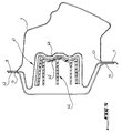
- the rear end 29 of the insert 20 comprises a flat face 30 extending transversely and bearing against the wafer 28.
- This flat face 30 carries three fingers, identified by 31, 32 and 33 which surround the reinforcing plate 24 extending on both sides of this sheet. Each finger extends in a direction normal to that of the face 30, and defines a lateral surface bearing against a side of the reinforcing plate 24 so as to block the rear end 29 transversely on the reinforcement 24.
- the reinforcing plate 24 has a shape defining three undulations 34, 35 and 36 in which engage the fingers 31, 32 and 33 respectively.
- the corrugations 34, 35 and 36 give the reinforcing plate 24 a cross section corresponding to the letter W, as can be seen in FIG.
- the fingers and the corrugations extend longitudinally, these corrugations defining a complementary profile of the space between the different fingers.
- the engagement of the fingers arranged in staggered rows, in the complementary corrugations, ensures complete blocking of the rear end 29.
- the insert is immobilized longitudinally thanks to the support of the face 30 on the slice 28, transversely due to the fact that these fingers each support laterally against a sidewall of the reinforcing plate 24, and vertically through the corrugations of the reinforcing sheet which constitute obstacles to a possible vertical movement of these fingers.
- each finger 31, 32 and 33 further comprises a gluing area, marked respectively by 31 ', 32' and 33 '.
- each gluing zone abuts against a side of the reinforcing plate 24, in a corresponding corrugation, to be glued effectively.
- the insert marked 35 also has a general shape of L comprising different sizing walls 36 and 37.
- Its rear end 38 also comprises a plane face 39 carrying a single locking pin 40 having a generally parallelepipedal shape and extending in a direction normal to the plane face 39.
- a reinforcing plate 41 also comprises an upper edge 42 and a lower edge 43 by which it is welded to the edges of the body side 3. It defines an edge 45 which extends in a transverse plane, and which is adapted to receive the rear plane face 39 of the insert to block it.
- the reinforcement plate 41 here comprises a main corrugation, 46, extending longitudinally, and having a U-section complementary to the section of the parallelepipedal finger 40.
- the finger 40 comprises a sizing surface 41, bearing against a side of the reinforcing plate 41, in the corrugation 46, to be completely secured to this reinforcing sheet.
- This insert 35 further comprises three locating tabs, marked at 48, 49 and 50. Each positioning tab protrudes from the main body constituted by the insert 35, extending outwardly to be located facing each other. a corresponding edge on the body side 3.
- these tongues 48, 49, 50 make it possible to position the insert 35 transversely while bearing on the corresponding edges of the body side 3, namely, respectively, the edges 9, 8 and 7.
- each locating tab is taken between an edge of the wing liner, or an edge of the inner spar, and a corresponding side edge. body to hold the insert in the median position in the cavity.
- the insert has a general shape of L to form a front foot reinforcement.
- the invention also applies to other body stiffening inserts, such as for example a central foot insert having a general shape corresponding to the letter T.
Landscapes
- Engineering & Computer Science (AREA)
- Chemical & Material Sciences (AREA)
- Combustion & Propulsion (AREA)
- Transportation (AREA)
- Mechanical Engineering (AREA)
- Architecture (AREA)
- Structural Engineering (AREA)
- Body Structure For Vehicles (AREA)
- Braking Systems And Boosters (AREA)
- Vibration Dampers (AREA)
Applications Claiming Priority (1)
| Application Number | Priority Date | Filing Date | Title |
|---|---|---|---|
| FR0509088A FR2890359B1 (fr) | 2005-09-06 | 2005-09-06 | Insert pour caisse de vehicule automobile |
Publications (3)
| Publication Number | Publication Date |
|---|---|
| EP1759959A2 true EP1759959A2 (de) | 2007-03-07 |
| EP1759959A3 EP1759959A3 (de) | 2007-04-18 |
| EP1759959B1 EP1759959B1 (de) | 2009-09-23 |
Family
ID=36370999
Family Applications (1)
| Application Number | Title | Priority Date | Filing Date |
|---|---|---|---|
| EP06300748A Not-in-force EP1759959B1 (de) | 2005-09-06 | 2006-07-03 | Verstärkungsteil für ein Kraftfahrzeug-Chassis |
Country Status (5)
| Country | Link |
|---|---|
| EP (1) | EP1759959B1 (de) |
| AT (1) | ATE443647T1 (de) |
| DE (1) | DE602006009351D1 (de) |
| ES (1) | ES2331485T3 (de) |
| FR (1) | FR2890359B1 (de) |
Cited By (20)
| Publication number | Priority date | Publication date | Assignee | Title |
|---|---|---|---|---|
| WO2009007004A1 (de) * | 2007-07-11 | 2009-01-15 | Bayerische Motoren Werke Aktiengesellschaft | Fahrzeugkarosserie mit einem biegeträger |
| EP2110296A3 (de) * | 2008-04-17 | 2010-04-28 | Eurostyle France | Strukturbaueinheit für Kraftfahrzeug |
| EP2409900A1 (de) * | 2010-07-21 | 2012-01-25 | Sika Technology AG | Auf Richtung einer Last ausgerichtete Verstärkung |
| WO2012087910A1 (en) | 2010-12-20 | 2012-06-28 | Sabic Innovative Plastics Ip B.V. | Reinforced body in white and method of making and using the same |
| US8336933B2 (en) | 2010-11-04 | 2012-12-25 | Sabic Innovative Plastics Ip B.V. | Energy absorbing device and methods of making and using the same |
| WO2013149706A1 (de) * | 2012-04-04 | 2013-10-10 | Audi Ag | Verbindungsanordnung von struktureinheiten und verfahren zum verbinden von struktureinheiten |
| US8864216B2 (en) | 2013-01-18 | 2014-10-21 | Sabic Global Technologies B.V. | Reinforced body in white and method of making and using the same |
| US9033404B2 (en) | 2013-03-14 | 2015-05-19 | Honda Motor Co., Ltd. | Encapsulated aluminum honeycomb structural stiffener |
| US9067550B2 (en) | 2013-01-18 | 2015-06-30 | Sabic Global Technologies B.V. | Polymer, energy absorber rail extension, methods of making and vehicles using the same |
| EP2238012B1 (de) | 2007-12-26 | 2016-03-16 | Sika Technology AG | Integrierter verstärkungsquerträger |
| WO2018022446A1 (en) * | 2016-07-28 | 2018-02-01 | Zephyros, Inc. | Multiple stage deformation reinforcement structure for impact absorption |
| US10106205B2 (en) | 2016-07-21 | 2018-10-23 | Zephyros, Inc. | Reinforcement structure |
| CN109927790A (zh) * | 2017-12-15 | 2019-06-25 | 蔚来汽车有限公司 | 用于前车身碰撞的力传递系统和汽车 |
| USD901347S1 (en) | 2015-12-29 | 2020-11-10 | Sabic Global Technologies B.V. | Roof component for a motor vehicle |
| US11008050B2 (en) | 2016-12-30 | 2021-05-18 | Sabic Global Technologies B.V. | Hybrid structures and methods of making the same |
| CN113165698A (zh) * | 2018-12-03 | 2021-07-23 | 泽菲罗斯有限公司 | 具有集成止挡装置的加强件 |
| EP3710340B1 (de) | 2017-11-15 | 2022-06-29 | Sika Technology AG | Vorrichtung zur verstärkung eines strukturelementes |
| US11603142B2 (en) | 2014-06-16 | 2023-03-14 | Sabic Global Technologies B.V. | Structural body of a vehicle having an energy absorbing device and a method of forming the energy absorbing device |
| US12012149B2 (en) | 2019-06-07 | 2024-06-18 | Zephyros, Inc. | Carrier to reinforce a frame of a vehicle and method of making |
| US12485967B2 (en) | 2019-06-07 | 2025-12-02 | Zephyros, Inc. | Carrier to reinforce a frame of a vehicle and method of making |
Families Citing this family (1)
| Publication number | Priority date | Publication date | Assignee | Title |
|---|---|---|---|---|
| CN108556917A (zh) * | 2017-12-30 | 2018-09-21 | 安徽大昌科技股份有限公司 | 一种加强型前副车架 |
Family Cites Families (3)
| Publication number | Priority date | Publication date | Assignee | Title |
|---|---|---|---|---|
| JP3063605B2 (ja) * | 1995-07-31 | 2000-07-12 | トヨタ自動車株式会社 | 自動車の車体上部の衝撃エネルギ吸収構造 |
| US6250711B1 (en) * | 1998-07-31 | 2001-06-26 | Toyota Jidosha Kabushiki Kaisha | Energy absorber securing structure and method |
| JP3909649B2 (ja) * | 2001-01-19 | 2007-04-25 | スズキ株式会社 | 自動車の側部車体構造 |
-
2005
- 2005-09-06 FR FR0509088A patent/FR2890359B1/fr not_active Expired - Fee Related
-
2006
- 2006-07-03 DE DE602006009351T patent/DE602006009351D1/de active Active
- 2006-07-03 EP EP06300748A patent/EP1759959B1/de not_active Not-in-force
- 2006-07-03 AT AT06300748T patent/ATE443647T1/de not_active IP Right Cessation
- 2006-07-03 ES ES06300748T patent/ES2331485T3/es active Active
Cited By (44)
| Publication number | Priority date | Publication date | Assignee | Title |
|---|---|---|---|---|
| WO2009007004A1 (de) * | 2007-07-11 | 2009-01-15 | Bayerische Motoren Werke Aktiengesellschaft | Fahrzeugkarosserie mit einem biegeträger |
| EP2238012B1 (de) | 2007-12-26 | 2016-03-16 | Sika Technology AG | Integrierter verstärkungsquerträger |
| EP2110296A3 (de) * | 2008-04-17 | 2010-04-28 | Eurostyle France | Strukturbaueinheit für Kraftfahrzeug |
| EP2409900A1 (de) * | 2010-07-21 | 2012-01-25 | Sika Technology AG | Auf Richtung einer Last ausgerichtete Verstärkung |
| WO2012010595A1 (en) * | 2010-07-21 | 2012-01-26 | Sika Technology Ag | Reinforcement aligned with axis of load |
| US8336933B2 (en) | 2010-11-04 | 2012-12-25 | Sabic Innovative Plastics Ip B.V. | Energy absorbing device and methods of making and using the same |
| US8474583B2 (en) | 2010-11-04 | 2013-07-02 | Sabic Innovative Plastics Ip B.V. | Impact device and methods of making and using the same |
| EP2985211A1 (de) * | 2010-12-20 | 2016-02-17 | SABIC Innovative Plastics IP B.V. | Verstärkte rohkarosserie und verfahren zur herstellung und verwendung davon |
| WO2012087910A1 (en) | 2010-12-20 | 2012-06-28 | Sabic Innovative Plastics Ip B.V. | Reinforced body in white and method of making and using the same |
| US8322780B2 (en) | 2010-12-20 | 2012-12-04 | Sabic Innovative Plastics Ip B.V. | Reinforced body in white and method of making and using the same |
| CN103261006A (zh) * | 2010-12-20 | 2013-08-21 | 沙特基础创新塑料Ip私人有限责任公司 | 增强型白车身及其制造和使用方法 |
| CN103261006B (zh) * | 2010-12-20 | 2016-06-15 | 沙特基础全球技术有限公司 | 增强型白车身及其制造和使用方法 |
| CN104203730B (zh) * | 2012-04-04 | 2016-08-24 | 奥迪股份公司 | 结构单元的连接装置和用于连接结构单元的方法 |
| CN104203730A (zh) * | 2012-04-04 | 2014-12-10 | 奥迪股份公司 | 结构单元的连接装置和用于连接结构单元的方法 |
| US9394009B2 (en) | 2012-04-04 | 2016-07-19 | Audi Ag | Connection arrangement of structural units and method for connecting structural units |
| WO2013149706A1 (de) * | 2012-04-04 | 2013-10-10 | Audi Ag | Verbindungsanordnung von struktureinheiten und verfahren zum verbinden von struktureinheiten |
| US9067550B2 (en) | 2013-01-18 | 2015-06-30 | Sabic Global Technologies B.V. | Polymer, energy absorber rail extension, methods of making and vehicles using the same |
| US8864216B2 (en) | 2013-01-18 | 2014-10-21 | Sabic Global Technologies B.V. | Reinforced body in white and method of making and using the same |
| US9469264B2 (en) | 2013-01-18 | 2016-10-18 | Sabic Global Technologies B.V. | Polymer, energy absorber rail extension, methods of making and vehicles using the same |
| US9771109B2 (en) | 2013-01-18 | 2017-09-26 | Sabic Global Technologies B.V. | Reinforced body in white and reinforcement therefor |
| US9033404B2 (en) | 2013-03-14 | 2015-05-19 | Honda Motor Co., Ltd. | Encapsulated aluminum honeycomb structural stiffener |
| US12384469B2 (en) | 2014-06-16 | 2025-08-12 | Sabic Global Technologies B.V. | Method of making a laminate, an energy absorbing device, an energy absorbing device composition, and a forming tool |
| US11603142B2 (en) | 2014-06-16 | 2023-03-14 | Sabic Global Technologies B.V. | Structural body of a vehicle having an energy absorbing device and a method of forming the energy absorbing device |
| USD901347S1 (en) | 2015-12-29 | 2020-11-10 | Sabic Global Technologies B.V. | Roof component for a motor vehicle |
| US10106205B2 (en) | 2016-07-21 | 2018-10-23 | Zephyros, Inc. | Reinforcement structure |
| US10800462B2 (en) | 2016-07-21 | 2020-10-13 | Zephyros, Inc. | Reinforcement structure |
| EP3957549B1 (de) | 2016-07-21 | 2024-02-28 | Zephyros, Inc. | Verstärkungsstruktur |
| US10196097B2 (en) | 2016-07-21 | 2019-02-05 | Zephyros, Inc. | Reinforcement structure |
| US10183699B2 (en) | 2016-07-28 | 2019-01-22 | Zephyros, Inc. | Multiple stage deformation reinforcement structure for impact absorption |
| US12286158B2 (en) | 2016-07-28 | 2025-04-29 | Zephyros, Inc. | Multiple stage deformation reinforcement structure for impact absorption |
| US10875579B2 (en) | 2016-07-28 | 2020-12-29 | Zephyros, Inc. | Multiple stage deformation reinforcement structure for impact absorption |
| CN109982917A (zh) * | 2016-07-28 | 2019-07-05 | 泽菲罗斯有限公司 | 用于吸收冲击的多级变形加强结构 |
| US11465686B2 (en) | 2016-07-28 | 2022-10-11 | Zephyros, Inc. | Multiple stage deformation reinforcement structure for impact absorption |
| US11565755B2 (en) | 2016-07-28 | 2023-01-31 | Zephyros, Inc. | Multiple stage deformation reinforcement structure for impact absorption |
| US10173727B2 (en) | 2016-07-28 | 2019-01-08 | Zephyros, Inc. | Multiple stage deformation reinforcement structure for impact absorption |
| EP4596375A3 (de) * | 2016-07-28 | 2025-10-15 | Zephyros Inc. | Mehrstufige verformungsverstärkungsstruktur zur stossdämpfung |
| WO2018022446A1 (en) * | 2016-07-28 | 2018-02-01 | Zephyros, Inc. | Multiple stage deformation reinforcement structure for impact absorption |
| US11008050B2 (en) | 2016-12-30 | 2021-05-18 | Sabic Global Technologies B.V. | Hybrid structures and methods of making the same |
| EP3710340B1 (de) | 2017-11-15 | 2022-06-29 | Sika Technology AG | Vorrichtung zur verstärkung eines strukturelementes |
| CN109927790A (zh) * | 2017-12-15 | 2019-06-25 | 蔚来汽车有限公司 | 用于前车身碰撞的力传递系统和汽车 |
| CN113165698A (zh) * | 2018-12-03 | 2021-07-23 | 泽菲罗斯有限公司 | 具有集成止挡装置的加强件 |
| CN113165698B (zh) * | 2018-12-03 | 2024-04-05 | 泽菲罗斯有限公司 | 具有集成止挡装置的加强件 |
| US12012149B2 (en) | 2019-06-07 | 2024-06-18 | Zephyros, Inc. | Carrier to reinforce a frame of a vehicle and method of making |
| US12485967B2 (en) | 2019-06-07 | 2025-12-02 | Zephyros, Inc. | Carrier to reinforce a frame of a vehicle and method of making |
Also Published As
| Publication number | Publication date |
|---|---|
| ATE443647T1 (de) | 2009-10-15 |
| ES2331485T3 (es) | 2010-01-05 |
| EP1759959B1 (de) | 2009-09-23 |
| EP1759959A3 (de) | 2007-04-18 |
| DE602006009351D1 (de) | 2009-11-05 |
| FR2890359A1 (fr) | 2007-03-09 |
| FR2890359B1 (fr) | 2007-11-30 |
Similar Documents
| Publication | Publication Date | Title |
|---|---|---|
| EP1759959B1 (de) | Verstärkungsteil für ein Kraftfahrzeug-Chassis | |
| EP2560839B1 (de) | Schutzplatte der befestigbar ist auf dem teil des körpers eines kraftfahrzeuges und ein fahrzeug ausgestattet mit einem solchen panel. | |
| EP1759964B1 (de) | Einlegeteil für eine Kraftfahrzeugkarosserie | |
| EP2142419A1 (de) | Unterer rahmen für ein automobil | |
| EP2678194B1 (de) | Halterung für einen sicherheitsgurtaufroller | |
| WO2015110735A1 (fr) | Structure de caisse d'un véhicule automobile avec renforts de répartition des efforts liés à un amortisseur arrière du véhicule | |
| FR2890361A1 (fr) | Insert pour caisse de vehicule automobile | |
| FR2959465A1 (fr) | Piece de carrosserie de vehicule automobile et structure d'extremite de vehicule automobile comprenant une telle piece. | |
| EP3148823B1 (de) | Fahrwerkslenker für ein fahrzeug | |
| EP3126209B1 (de) | Verstärkte kraftfahrzeug struktur | |
| EP4359289B1 (de) | Fahrzeugkarosserie mit verstärktem untergestell | |
| EP3097000B1 (de) | Karosserieaufbau eines kraftfahrzeugs mit verstärkungen zur verteilung der kräfte in verbindung mit einem hinteren stossdämpfer des fahrzeugs | |
| FR2934538A1 (fr) | Caisse de vehicule automobile et vehicule comprenant une telle caisse. | |
| EP3405382B1 (de) | Teil zur verstärkung eines unteren querträgers für eine fensteröffnung | |
| WO2007006996A2 (fr) | Aile avant de vehicule automobile a cloison d'etancheite deformable | |
| EP4507929B1 (de) | Haubeninnenverkleidung für ein kraftfahrzeug | |
| FR3141433A1 (fr) | Caisse de véhicule à support de suspension à faible encombrement latéral dans un passage de roue | |
| EP3375697B1 (de) | A-säule eines fahrzeugs, die mit einer befestigungshalterung für eine querstrebe des armaturenbretts eines kraftfahrzeugs ausgestattet ist | |
| EP2670651B1 (de) | Schwellenabdeckung für ein kraftfahrzeug mit einer absplitterungsverhindernden beschichtung ohne regenwasserabflussblockierung und fahrzeug mit einer solchen schwellenabdeckung | |
| FR2832110A1 (fr) | Poutre de pare-chocs a structure d'entretoise amelioree, module d'extremite longitudinale et vehicule automobile correspondants | |
| FR3148984A1 (fr) | Déflecteur aéraulique pour véhicule automobile | |
| EP1637442B1 (de) | Frontendmodul und dessen Montageverfahren | |
| EP4671077A1 (de) | Seitenwand eines wagenkastens eines schienenfahrzeugs, wagenkasten eines schienenfahrzeugs mit einer solchen seitenwand und schienenfahrzeug mit einem solchen wagenkasten | |
| FR3064582A1 (fr) | Structure arriere de vehicule | |
| FR2884201A1 (fr) | Ensemble de pare-chocs de vehicule automobile et vehicule automobile comprenant un tel ensemble. |
Legal Events
| Date | Code | Title | Description |
|---|---|---|---|
| PUAI | Public reference made under article 153(3) epc to a published international application that has entered the european phase |
Free format text: ORIGINAL CODE: 0009012 |
|
| AK | Designated contracting states |
Kind code of ref document: A2 Designated state(s): AT BE BG CH CY CZ DE DK EE ES FI FR GB GR HU IE IS IT LI LT LU LV MC NL PL PT RO SE SI SK TR |
|
| AX | Request for extension of the european patent |
Extension state: AL BA HR MK YU |
|
| PUAL | Search report despatched |
Free format text: ORIGINAL CODE: 0009013 |
|
| AK | Designated contracting states |
Kind code of ref document: A3 Designated state(s): AT BE BG CH CY CZ DE DK EE ES FI FR GB GR HU IE IS IT LI LT LU LV MC NL PL PT RO SE SI SK TR |
|
| AX | Request for extension of the european patent |
Extension state: AL BA HR MK YU |
|
| RIC1 | Information provided on ipc code assigned before grant |
Ipc: B62D 21/15 20060101AFI20061211BHEP Ipc: B62D 29/00 20060101ALI20070315BHEP |
|
| 17P | Request for examination filed |
Effective date: 20070510 |
|
| AKX | Designation fees paid |
Designated state(s): AT BE BG CH CY CZ DE DK EE ES FI FR GB GR HU IE IS IT LI LT LU LV MC NL PL PT RO SE SI SK TR |
|
| GRAP | Despatch of communication of intention to grant a patent |
Free format text: ORIGINAL CODE: EPIDOSNIGR1 |
|
| GRAS | Grant fee paid |
Free format text: ORIGINAL CODE: EPIDOSNIGR3 |
|
| GRAA | (expected) grant |
Free format text: ORIGINAL CODE: 0009210 |
|
| RIN1 | Information on inventor provided before grant (corrected) |
Inventor name: SAILLET, PHILIPPE Inventor name: PATOIS, CHRISTOPHE Inventor name: KAUFFMANN, MICHEL |
|
| AK | Designated contracting states |
Kind code of ref document: B1 Designated state(s): AT BE BG CH CY CZ DE DK EE ES FI FR GB GR HU IE IS IT LI LT LU LV MC NL PL PT RO SE SI SK TR |
|
| REG | Reference to a national code |
Ref country code: GB Ref legal event code: FG4D Free format text: NOT ENGLISH |
|
| REG | Reference to a national code |
Ref country code: CH Ref legal event code: EP |
|
| REG | Reference to a national code |
Ref country code: IE Ref legal event code: FG4D |
|
| REG | Reference to a national code |
Ref country code: GB Ref legal event code: 746 Effective date: 20091012 |
|
| REF | Corresponds to: |
Ref document number: 602006009351 Country of ref document: DE Date of ref document: 20091105 Kind code of ref document: P |
|
| REG | Reference to a national code |
Ref country code: ES Ref legal event code: FG2A Ref document number: 2331485 Country of ref document: ES Kind code of ref document: T3 |
|
| PG25 | Lapsed in a contracting state [announced via postgrant information from national office to epo] |
Ref country code: FI Free format text: LAPSE BECAUSE OF FAILURE TO SUBMIT A TRANSLATION OF THE DESCRIPTION OR TO PAY THE FEE WITHIN THE PRESCRIBED TIME-LIMIT Effective date: 20090923 Ref country code: SE Free format text: LAPSE BECAUSE OF FAILURE TO SUBMIT A TRANSLATION OF THE DESCRIPTION OR TO PAY THE FEE WITHIN THE PRESCRIBED TIME-LIMIT Effective date: 20090923 Ref country code: LT Free format text: LAPSE BECAUSE OF FAILURE TO SUBMIT A TRANSLATION OF THE DESCRIPTION OR TO PAY THE FEE WITHIN THE PRESCRIBED TIME-LIMIT Effective date: 20090923 |
|
| LTIE | Lt: invalidation of european patent or patent extension |
Effective date: 20090923 |
|
| PG25 | Lapsed in a contracting state [announced via postgrant information from national office to epo] |
Ref country code: LV Free format text: LAPSE BECAUSE OF FAILURE TO SUBMIT A TRANSLATION OF THE DESCRIPTION OR TO PAY THE FEE WITHIN THE PRESCRIBED TIME-LIMIT Effective date: 20090923 Ref country code: SI Free format text: LAPSE BECAUSE OF FAILURE TO SUBMIT A TRANSLATION OF THE DESCRIPTION OR TO PAY THE FEE WITHIN THE PRESCRIBED TIME-LIMIT Effective date: 20090923 Ref country code: PL Free format text: LAPSE BECAUSE OF FAILURE TO SUBMIT A TRANSLATION OF THE DESCRIPTION OR TO PAY THE FEE WITHIN THE PRESCRIBED TIME-LIMIT Effective date: 20090923 |
|
| NLV1 | Nl: lapsed or annulled due to failure to fulfill the requirements of art. 29p and 29m of the patents act | ||
| PG25 | Lapsed in a contracting state [announced via postgrant information from national office to epo] |
Ref country code: CY Free format text: LAPSE BECAUSE OF FAILURE TO SUBMIT A TRANSLATION OF THE DESCRIPTION OR TO PAY THE FEE WITHIN THE PRESCRIBED TIME-LIMIT Effective date: 20090923 |
|
| REG | Reference to a national code |
Ref country code: IE Ref legal event code: FD4D |
|
| PG25 | Lapsed in a contracting state [announced via postgrant information from national office to epo] |
Ref country code: RO Free format text: LAPSE BECAUSE OF FAILURE TO SUBMIT A TRANSLATION OF THE DESCRIPTION OR TO PAY THE FEE WITHIN THE PRESCRIBED TIME-LIMIT Effective date: 20090923 Ref country code: PT Free format text: LAPSE BECAUSE OF FAILURE TO SUBMIT A TRANSLATION OF THE DESCRIPTION OR TO PAY THE FEE WITHIN THE PRESCRIBED TIME-LIMIT Effective date: 20100125 Ref country code: EE Free format text: LAPSE BECAUSE OF FAILURE TO SUBMIT A TRANSLATION OF THE DESCRIPTION OR TO PAY THE FEE WITHIN THE PRESCRIBED TIME-LIMIT Effective date: 20090923 Ref country code: IE Free format text: LAPSE BECAUSE OF FAILURE TO SUBMIT A TRANSLATION OF THE DESCRIPTION OR TO PAY THE FEE WITHIN THE PRESCRIBED TIME-LIMIT Effective date: 20090923 Ref country code: IS Free format text: LAPSE BECAUSE OF FAILURE TO SUBMIT A TRANSLATION OF THE DESCRIPTION OR TO PAY THE FEE WITHIN THE PRESCRIBED TIME-LIMIT Effective date: 20100123 Ref country code: CZ Free format text: LAPSE BECAUSE OF FAILURE TO SUBMIT A TRANSLATION OF THE DESCRIPTION OR TO PAY THE FEE WITHIN THE PRESCRIBED TIME-LIMIT Effective date: 20090923 |
|
| PG25 | Lapsed in a contracting state [announced via postgrant information from national office to epo] |
Ref country code: SK Free format text: LAPSE BECAUSE OF FAILURE TO SUBMIT A TRANSLATION OF THE DESCRIPTION OR TO PAY THE FEE WITHIN THE PRESCRIBED TIME-LIMIT Effective date: 20090923 |
|
| PG25 | Lapsed in a contracting state [announced via postgrant information from national office to epo] |
Ref country code: AT Free format text: LAPSE BECAUSE OF FAILURE TO SUBMIT A TRANSLATION OF THE DESCRIPTION OR TO PAY THE FEE WITHIN THE PRESCRIBED TIME-LIMIT Effective date: 20090923 |
|
| PG25 | Lapsed in a contracting state [announced via postgrant information from national office to epo] |
Ref country code: DK Free format text: LAPSE BECAUSE OF FAILURE TO SUBMIT A TRANSLATION OF THE DESCRIPTION OR TO PAY THE FEE WITHIN THE PRESCRIBED TIME-LIMIT Effective date: 20090923 Ref country code: NL Free format text: LAPSE BECAUSE OF FAILURE TO SUBMIT A TRANSLATION OF THE DESCRIPTION OR TO PAY THE FEE WITHIN THE PRESCRIBED TIME-LIMIT Effective date: 20090923 |
|
| PLBE | No opposition filed within time limit |
Free format text: ORIGINAL CODE: 0009261 |
|
| STAA | Information on the status of an ep patent application or granted ep patent |
Free format text: STATUS: NO OPPOSITION FILED WITHIN TIME LIMIT |
|
| 26N | No opposition filed |
Effective date: 20100624 |
|
| PG25 | Lapsed in a contracting state [announced via postgrant information from national office to epo] |
Ref country code: GR Free format text: LAPSE BECAUSE OF FAILURE TO SUBMIT A TRANSLATION OF THE DESCRIPTION OR TO PAY THE FEE WITHIN THE PRESCRIBED TIME-LIMIT Effective date: 20091224 |
|
| BERE | Be: lapsed |
Owner name: PEUGEOT CITROEN AUTOMOBILES SA Effective date: 20100731 |
|
| PG25 | Lapsed in a contracting state [announced via postgrant information from national office to epo] |
Ref country code: MC Free format text: LAPSE BECAUSE OF NON-PAYMENT OF DUE FEES Effective date: 20100731 |
|
| REG | Reference to a national code |
Ref country code: CH Ref legal event code: PL |
|
| REG | Reference to a national code |
Ref country code: ES Ref legal event code: GC2A Effective date: 20110316 |
|
| PG25 | Lapsed in a contracting state [announced via postgrant information from national office to epo] |
Ref country code: CH Free format text: LAPSE BECAUSE OF NON-PAYMENT OF DUE FEES Effective date: 20100731 Ref country code: LI Free format text: LAPSE BECAUSE OF NON-PAYMENT OF DUE FEES Effective date: 20100731 |
|
| PG25 | Lapsed in a contracting state [announced via postgrant information from national office to epo] |
Ref country code: BE Free format text: LAPSE BECAUSE OF NON-PAYMENT OF DUE FEES Effective date: 20100731 |
|
| PG25 | Lapsed in a contracting state [announced via postgrant information from national office to epo] |
Ref country code: BG Free format text: LAPSE BECAUSE OF FAILURE TO SUBMIT A TRANSLATION OF THE DESCRIPTION OR TO PAY THE FEE WITHIN THE PRESCRIBED TIME-LIMIT Effective date: 20090923 Ref country code: HU Free format text: LAPSE BECAUSE OF FAILURE TO SUBMIT A TRANSLATION OF THE DESCRIPTION OR TO PAY THE FEE WITHIN THE PRESCRIBED TIME-LIMIT Effective date: 20100324 Ref country code: LU Free format text: LAPSE BECAUSE OF NON-PAYMENT OF DUE FEES Effective date: 20100703 |
|
| PG25 | Lapsed in a contracting state [announced via postgrant information from national office to epo] |
Ref country code: TR Free format text: LAPSE BECAUSE OF FAILURE TO SUBMIT A TRANSLATION OF THE DESCRIPTION OR TO PAY THE FEE WITHIN THE PRESCRIBED TIME-LIMIT Effective date: 20090923 |
|
| REG | Reference to a national code |
Ref country code: FR Ref legal event code: PLFP Year of fee payment: 11 |
|
| REG | Reference to a national code |
Ref country code: FR Ref legal event code: PLFP Year of fee payment: 12 |
|
| PGFP | Annual fee paid to national office [announced via postgrant information from national office to epo] |
Ref country code: GB Payment date: 20170620 Year of fee payment: 12 |
|
| PGFP | Annual fee paid to national office [announced via postgrant information from national office to epo] |
Ref country code: GB Payment date: 20170802 Year of fee payment: 12 |
|
| REG | Reference to a national code |
Ref country code: FR Ref legal event code: PLFP Year of fee payment: 13 |
|
| REG | Reference to a national code |
Ref country code: FR Ref legal event code: CA Effective date: 20180312 Ref country code: FR Ref legal event code: CD Owner name: PEUGEOT CITROEN AUTOMOBILES SA, FR Effective date: 20180312 |
|
| PGFP | Annual fee paid to national office [announced via postgrant information from national office to epo] |
Ref country code: FR Payment date: 20180621 Year of fee payment: 13 |
|
| PGFP | Annual fee paid to national office [announced via postgrant information from national office to epo] |
Ref country code: ES Payment date: 20180801 Year of fee payment: 13 Ref country code: DE Payment date: 20180620 Year of fee payment: 13 |
|
| GBPC | Gb: european patent ceased through non-payment of renewal fee |
Effective date: 20180703 |
|
| PG25 | Lapsed in a contracting state [announced via postgrant information from national office to epo] |
Ref country code: GB Free format text: LAPSE BECAUSE OF NON-PAYMENT OF DUE FEES Effective date: 20180703 |
|
| PG25 | Lapsed in a contracting state [announced via postgrant information from national office to epo] |
Ref country code: IT Free format text: LAPSE BECAUSE OF NON-PAYMENT OF DUE FEES Effective date: 20180703 |
|
| REG | Reference to a national code |
Ref country code: DE Ref legal event code: R119 Ref document number: 602006009351 Country of ref document: DE |
|
| PG25 | Lapsed in a contracting state [announced via postgrant information from national office to epo] |
Ref country code: DE Free format text: LAPSE BECAUSE OF NON-PAYMENT OF DUE FEES Effective date: 20200201 |
|
| PG25 | Lapsed in a contracting state [announced via postgrant information from national office to epo] |
Ref country code: FR Free format text: LAPSE BECAUSE OF NON-PAYMENT OF DUE FEES Effective date: 20190731 |
|
| REG | Reference to a national code |
Ref country code: ES Ref legal event code: FD2A Effective date: 20201126 |
|
| PG25 | Lapsed in a contracting state [announced via postgrant information from national office to epo] |
Ref country code: ES Free format text: LAPSE BECAUSE OF NON-PAYMENT OF DUE FEES Effective date: 20190704 |