EP1759959A2 - Insert de renforcement pour caisse de véhicule automobile - Google Patents
Insert de renforcement pour caisse de véhicule automobile Download PDFInfo
- Publication number
- EP1759959A2 EP1759959A2 EP06300748A EP06300748A EP1759959A2 EP 1759959 A2 EP1759959 A2 EP 1759959A2 EP 06300748 A EP06300748 A EP 06300748A EP 06300748 A EP06300748 A EP 06300748A EP 1759959 A2 EP1759959 A2 EP 1759959A2
- Authority
- EP
- European Patent Office
- Prior art keywords
- insert
- fingers
- spar
- reinforcing
- finger
- Prior art date
- Legal status (The legal status is an assumption and is not a legal conclusion. Google has not performed a legal analysis and makes no representation as to the accuracy of the status listed.)
- Granted
Links
Images


Classifications
-
- B—PERFORMING OPERATIONS; TRANSPORTING
- B62—LAND VEHICLES FOR TRAVELLING OTHERWISE THAN ON RAILS
- B62D—MOTOR VEHICLES; TRAILERS
- B62D29/00—Superstructures, understructures, or sub-units thereof, characterised by the material thereof
- B62D29/001—Superstructures, understructures, or sub-units thereof, characterised by the material thereof characterised by combining metal and synthetic material
-
- B—PERFORMING OPERATIONS; TRANSPORTING
- B62—LAND VEHICLES FOR TRAVELLING OTHERWISE THAN ON RAILS
- B62D—MOTOR VEHICLES; TRAILERS
- B62D21/00—Understructures, i.e. chassis frame on which a vehicle body may be mounted
- B62D21/15—Understructures, i.e. chassis frame on which a vehicle body may be mounted having impact absorbing means, e.g. a frame designed to permanently or temporarily change shape or dimension upon impact with another body
-
- B—PERFORMING OPERATIONS; TRANSPORTING
- B62—LAND VEHICLES FOR TRAVELLING OTHERWISE THAN ON RAILS
- B62D—MOTOR VEHICLES; TRAILERS
- B62D29/00—Superstructures, understructures, or sub-units thereof, characterised by the material thereof
- B62D29/001—Superstructures, understructures, or sub-units thereof, characterised by the material thereof characterised by combining metal and synthetic material
- B62D29/005—Superstructures, understructures, or sub-units thereof, characterised by the material thereof characterised by combining metal and synthetic material preformed metal and synthetic material elements being joined together, e.g. by adhesives
Definitions
- the invention relates to a stiffening insert for a motor vehicle body, intended to be mounted in a cavity defined by at least two sheets welded to one another.
- the fund of motor vehicles includes one or more stiffening inserts intended to reduce these deformations.
- Such an insert is mounted at the junction of two structural elements of the body, these structural elements being for example a spar and a front foot of the body which are hollow beams.
- the stiffening insert is for example a plastic part formed of one or more walls reinforced by ribs, which defines a general three-dimensional shape complementary to the cavity in which it is mounted.
- This insert is rigidly attached to one or more of the plates delimiting the cavity in which it is mounted to reduce their deformations.
- This insert is rigidly attached to one or more of the plates delimiting the cavity in which it is mounted to reduce their deformations.
- the inclination taken by the foot under the effect of the shock is reduced by the presence of the insert.
- Such an insert is conditioned by its attachment to the sheets that surround it.
- such an insert is generally fixed by gluing, being coated with glue and positioned in one of the sheets before welding of the complementary sheets.
- the glue used is a foaming adhesive, that is to say capable of filling more or less important gaps and can vary significantly between a box and another.
- this foaming adhesive must also ensure optimum cohesion between the sheet and the insert, so that it is a glue with a very high cost.
- the object of the invention is to overcome this disadvantage by proposing an insert that can be fixed at a lower cost.
- the subject of the invention is a stiffening insert for a motor vehicle body intended to be inserted into a cavity delimited by at least two sheets welded to each other and by a reinforcing sheet extending between these two sheets, this insert having an end adapted to abut against a wafer of the reinforcing sheet, and wherein this end carries at least one locking finger adapted to bear against a sidewall of the reinforcing sheet.
- each finger is carried by a flat face of the end of the insert.
- the insert comprises at least two fingers adapted to bear on two opposite sides of the reinforcing sheet.
- the insert comprises three fingers arranged in quincunxes.
- At least one finger of the insert comprises a sizing zone.
- the insert has a general shape corresponding to the letter T to stiffen a base of the middle body foot being at least partially interposed between a body side and an inner spar.
- the insert has a general shape of a square to stiffen a base of the front foot box being at least partially interposed between a body side and an inner beam.
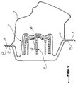
- Figure 1 is a view of a motor vehicle body part corresponding to a junction between a spar 1 extending horizontally and a front foot 2 extending vertically.
- This Figure 1 is an internal view, that is to say, representing the junction as seen from inside the box.
- the spar 1 and the front foot 2 are delimited, towards the outside of the vehicle by the same sheet called body side 3, which locally has a general shape L.
- This side of the body 3 has a concave shape which extends towards the rear of the plane of FIG.
- This body side 3 comprises a lower part 4, and an upper part 5 extending at right angles to the lower part, and starting from a end of this lower part 4.
- the lower part 4 extends horizontally, it corresponds to the spar 1, and is delimited in the lower part by a lower horizontal edge 7, and upwards by an upper horizontal edge 8.
- This lower part 4 is extended by the upper part 5 which extends vertically and corresponds to the front foot 2.
- This upper part is delimited on the one hand by a rear vertical edge 9 extending the upper horizontal edge 8, and secondly by a vertical front edge 10 extending the lower horizontal edge 7.
- the rear vertical edge 9 joins the upper horizontal edge 8 at a first curved zone 11, and the front vertical edge 10 joins the lower horizontal edge 7 at a second curved zone 12.
- the curved zones 11 and 12 delimit substantially the junction between the spar 1 and the front foot 2, they correspond to the base of the front foot 2.
- the lower part 4 is completed by a sheet called inner spar, which is marked by 16 in Figure 2, to form a hollow beam constituting the spar 1.
- This inner spar 16 is also delimited by an upper edge 17 and a lower edge 18. It is secured to the lower part 4 by welding its lower and upper edges respectively to the lower and upper horizontal edge 7 and 8.
- the upper part 5 is also completed by an inner upright called the front wing liner, not shown, which has its edges welded to the rear and front vertical edges 9 and 10 to form the front foot 2.
- the spar 1 and the front foot 2 thus constitute two hollow beams extending in the extension from each other being arranged in L, and defining an internal cavity including at their junction.
- the junction of the spar 1 and the front foot 2 is stiffened by an insert 20 which is placed in the cavity defined by the foot and middle spar, at their junction.
- This insert 20 is for example positioned in the body side 3 before assembly of the inner spar 16 and the wing liner by welding their respective edges to the edges of the body side. After welding, this insert 20 is thus trapped in the cavity that it reinforces.
- the insert 20 is here made of plastic material, and has a general shape complementary to the cavity in which it is mounted. It mainly comprises one or more walls, which are stiffened by internal ribs locally defining a reinforced structure close to a honeycomb structure.
- This insert 20 has a general shape corresponding to the letter L, and it comprises various external walls, marked by 21, 22 and 23 which are distributed to follow the inner spar 16, the front wing liner, and the body side 3 , when the insert is in place.
- the blocking of the insert 20 is completed by a reinforcing sheet 24 located in the spar 1, at a distance from the front foot 2.
- This reinforcing sheet 24 is located between the lower portion 4 of the spar, and the inner spar 16 It has edges 26 and 27 which are welded to the lower and upper horizontal edges 7 and 8 in a rear zone of the body side 3.
- This reinforcing sheet 24 constitutes a stop of the insert 20 having a wafer 28 which extends in a transverse plane of the spar 1, and against which a rear end 29 of the insert 20 bears.
- this stop prevents a displacement of the insert 20 towards the rear of the vehicle, so that it performs its function of stiffening.
- the rear end 29 of the insert 20 comprises a flat face 30 extending transversely and bearing against the wafer 28.
- This flat face 30 carries three fingers, identified by 31, 32 and 33 which surround the reinforcing plate 24 extending on both sides of this sheet. Each finger extends in a direction normal to that of the face 30, and defines a lateral surface bearing against a side of the reinforcing plate 24 so as to block the rear end 29 transversely on the reinforcement 24.
- the reinforcing plate 24 has a shape defining three undulations 34, 35 and 36 in which engage the fingers 31, 32 and 33 respectively.
- the corrugations 34, 35 and 36 give the reinforcing plate 24 a cross section corresponding to the letter W, as can be seen in FIG.
- the fingers and the corrugations extend longitudinally, these corrugations defining a complementary profile of the space between the different fingers.
- the engagement of the fingers arranged in staggered rows, in the complementary corrugations, ensures complete blocking of the rear end 29.
- the insert is immobilized longitudinally thanks to the support of the face 30 on the slice 28, transversely due to the fact that these fingers each support laterally against a sidewall of the reinforcing plate 24, and vertically through the corrugations of the reinforcing sheet which constitute obstacles to a possible vertical movement of these fingers.
- each finger 31, 32 and 33 further comprises a gluing area, marked respectively by 31 ', 32' and 33 '.
- each gluing zone abuts against a side of the reinforcing plate 24, in a corresponding corrugation, to be glued effectively.
- the insert marked 35 also has a general shape of L comprising different sizing walls 36 and 37.
- Its rear end 38 also comprises a plane face 39 carrying a single locking pin 40 having a generally parallelepipedal shape and extending in a direction normal to the plane face 39.
- a reinforcing plate 41 also comprises an upper edge 42 and a lower edge 43 by which it is welded to the edges of the body side 3. It defines an edge 45 which extends in a transverse plane, and which is adapted to receive the rear plane face 39 of the insert to block it.
- the reinforcement plate 41 here comprises a main corrugation, 46, extending longitudinally, and having a U-section complementary to the section of the parallelepipedal finger 40.
- the finger 40 comprises a sizing surface 41, bearing against a side of the reinforcing plate 41, in the corrugation 46, to be completely secured to this reinforcing sheet.
- This insert 35 further comprises three locating tabs, marked at 48, 49 and 50. Each positioning tab protrudes from the main body constituted by the insert 35, extending outwardly to be located facing each other. a corresponding edge on the body side 3.
- these tongues 48, 49, 50 make it possible to position the insert 35 transversely while bearing on the corresponding edges of the body side 3, namely, respectively, the edges 9, 8 and 7.
- each locating tab is taken between an edge of the wing liner, or an edge of the inner spar, and a corresponding side edge. body to hold the insert in the median position in the cavity.
- the insert has a general shape of L to form a front foot reinforcement.
- the invention also applies to other body stiffening inserts, such as for example a central foot insert having a general shape corresponding to the letter T.
Landscapes
- Engineering & Computer Science (AREA)
- Chemical & Material Sciences (AREA)
- Combustion & Propulsion (AREA)
- Transportation (AREA)
- Mechanical Engineering (AREA)
- Architecture (AREA)
- Structural Engineering (AREA)
- Body Structure For Vehicles (AREA)
- Braking Systems And Boosters (AREA)
- Vibration Dampers (AREA)
Abstract
Description
- L'invention concerne un insert de rigidification pour caisse de véhicule automobile, destiné à être monté dans une cavité délimitée par au moins deux tôles soudées l'une à l'autre.
- Afin de respecter les normes en vigueur en matière de déformation de la caisse suite à un choc correspondant par exemple à un accident, la caisse des véhicules automobiles comprend un ou plusieurs inserts de rigidification destinés à réduire ces déformations.
- Un tel insert est monté à la jonction de deux éléments structuraux de la caisse, ces éléments structuraux étant par exemple un longeron et un pied avant de la caisse qui constituent des poutres creuses.
- Ces éléments ainsi que leur jonction sont formés par différentes tôles assemblées par soudage des bords respectifs de ces tôles, ce qui délimite la zone creuse ou cavité, notamment au niveau de la jonction en elle-même.
- L'insert de rigidification est par exemple une pièce en matière plastique formée d'une ou plusieurs parois renforcées par des nervures, qui définit une forme générale tridimensionnelle complémentaire de la cavité dans laquelle il est monté.
- Cet insert est rigidement fixé à une ou plusieurs des tôles délimitant la cavité dans laquelle il est monté pour réduire leurs déformations. Dans le cas d'un insert renforçant une jonction entre un longeron et un pied avant perpendiculaire à ce longeron, l'inclinaison prise par le pied sous l'effet du choc est diminuée par la présence de l'insert.
- L'efficacité d'un tel insert est conditionnée par sa fixation aux tôles qui l'entourent. A cet effet, un tel insert est généralement fixé par collage, en étant enduit de colle et positionné dans l'une des tôles avant soudage des tôles complémentaires.
- Compte tenu des dispersions géométriques importantes de l'assemblage de tôles soudées, la colle utilisée est une colle moussante, c'est à dire capable de combler des interstices plus ou moins importants et pouvant varier de façon significative entre une caisse et une autre.
- Mais cette colle moussante doit également assurer une cohésion optimale entre la tôle et l'insert, de sorte qu'il s'agit d'une colle ayant un coût très important.
- Le but de l'invention est de remédier à cet inconvénient en proposant un insert pouvant être fixé à moindre coût.
- A cet effet, l'invention a pour objet un insert de rigidification pour caisse de véhicule automobile, destiné à être inséré dans une cavité délimitée par au moins deux tôles soudées l'une à l'autre et par une tôle de renfort s'étendant entre ces deux tôles, cet insert ayant une extrémité apte à venir en appui contre une tranche de la tôle de renfort, et dans lequel cette extrémité porte au moins un doigt de blocage apte à venir en appui contre un flanc de la tôle de renfort.
- Selon une caractéristique de l'invention, chaque doigt est porté par une face plane de l'extrémité de l'insert.
- Selon une autre caractéristique de l'invention, l'insert comprend au moins deux doigts aptes à venir en appui sur deux flancs opposés de la tôle de renfort.
- Selon une autre caractéristique de l'invention, l'insert comprend trois doigts disposés en quinconces.
- Selon une autre caractéristique, de l'invention, au moins un doigt de l'insert comprend une zone d'encollage.
- Selon une autre caractéristique de l'invention, l'insert a une forme générale correspondant à la lettre T pour rigidifier une embase de pied milieu de caisse en étant intercalé au moins partiellement entre un côté de caisse et un longeron intérieur.
- Selon une autre caractéristique de l'invention, l'insert a une forme générale d'équerre pour rigidifier une embase de pied avant de caisse en étant intercalé au moins partiellement entre un côté de caisse et un longeron intérieur.
- L'invention sera maintenant décrite plus en détail, et en référence aux dessins annexés qui en illustrent une forme de réalisation à titre d'exemple non limitatif.
- La figure 1 est une vue d'ensemble d'une jonction renforcée par un insert à trois doigts selon l'invention;
- La figure 2 est une vue en coupe transversale de la jonction de la figure 1 au niveau des doigts ;
- La figure 3 est une vue en perspective des doigts de l'insert des figures 1 et 2 ;
- La figure 4 est une vue d'ensemble d'une jonction renforcée par un insert à un doigt selon l'invention ;
- La figure 5 est une vue en coupe transversale de la jonction de la figure 4 au niveau du doigt.
- La figure 1 est une vue d'une partie de caisse de véhicule automobile correspondant à une jonction entre un longeron 1 s'étendant horizontalement et un pied avant 2 s'étendant verticalement. Cette figure 1 est un vue interne, c'est-à-dire représentant la jonction telle que vue depuis l'intérieur de la caisse.
- Dans l'exemple de la figure 1, le longeron 1 et le pied avant 2 sont délimités, vers l'extérieur du véhicule par une même tôle appelée côté de caisse 3, qui a localement une forme générale de L. Ce côté de caisse 3 a une forme concave qui s'étend vers l'arrière du plan de la figure 1.
- Ce côté de caisse 3 comprend une partie inférieure 4, et une partie supérieure 5 s'étendant à angle droit par rapport à la partie inférieure, et partant d'une extrémité de cette partie inférieure 4. La partie inférieure 4 s'étend horizontalement, elle correspond au longeron 1, et est délimitée en partie basse par un bord horizontal inférieur 7, et vers le haut par un bord horizontal supérieur 8.
- Cette partie inférieure 4 est prolongée par la partie supérieure 5 qui s'étend verticalement et correspond au pied avant 2. Cette partie supérieure est délimitée d'une part par un bord vertical arrière 9 prolongeant le bord horizontal supérieur 8, et d'autre part par un bord vertical avant 10 prolongeant le bord horizontal inférieur 7.
- Le bord vertical arrière 9 rejoint le bord horizontal supérieur 8 au niveau d'une première zone courbe 11, et le bord vertical avant 10 rejoint le bord horizontal inférieur 7 au niveau d'une seconde zone courbe 12. Les zones courbes 11 et 12 délimitent sensiblement la jonction entre le longeron 1 et le pied avant 2, elles correspondent à l'embase du pied avant 2.
- La partie inférieure 4 est complétée par une tôle appelée longeron intérieur, qui est repéré par 16 sur la figure 2, pour former une poutre creuse constituant le longeron 1. Ce longeron intérieur 16 est également délimité par un bord supérieur 17 et par un bord inférieur 18. Il est solidarisé à la partie inférieure 4 par soudage de ses bords inférieur et supérieur, respectivement au bord horizontal inférieur et supérieur 7 et 8.
- De façon analogue, la partie supérieure 5 est également complétée par un montant intérieur appelé doublure d'aile avant, non représentée, qui a ses bords soudés aux bords verticaux arrière et avant 9 et 10 pour former le pied avant 2.
- Le longeron 1 et le pied avant 2 constituent ainsi deux poutres creuses s'étendant dans le prolongement l'une de l'autre en étant disposées en L, et définissant une cavité interne y compris au niveau de leur jonction.
- Comme visible en figure 1, la jonction du longeron 1 et du pied avant 2 est rigidifiée par un insert 20 qui est placé dans la cavité délimitée par ce pied milieu et ce longeron, au niveau de leur jonction.
- Cet insert 20 est par exemple positionné dans le côté de caisse 3 avant assemblage du longeron intérieur 16 et de la doublure d'aile par soudage de leurs bords respectifs aux bords du côté de caisse. Après soudage, cet insert 20 est ainsi prisonnier de la cavité qu'il renforce.
- L'insert 20 est ici fabriqué en matière plastique, et a une forme générale complémentaire de la cavité dans laquelle il est monté. Il comprend principalement une ou plusieurs parois, qui sont rigidifiées par des nervures internes définissant localement une structure renforcée proche d'une structure de type nid d'abeilles.
- Cet insert 20 a une forme générale correspondant à la lettre L, et il comprend différentes parois externes, repérées par 21, 22 et 23 qui sont réparties pour longer le longeron intérieur 16, la doublure d'aile avant, et le côté de caisse 3, lorsque l'insert est en place.
- Ces parois 21, 22 et 23 sont encollées avec une colle moussante spécifique, pour assurer qu'après montage, l'insert soit solidarisé aux tôles.
- Le blocage de l'insert 20 est complété par une tôle de renfort 24 située dans le longeron 1, à une certaine distance du pied avant 2. Cette tôle de renfort 24 est située entre la partie inférieure 4 du longeron, et le longeron intérieur 16. Elle présente des bords 26 et 27 qui sont soudés aux bords horizontal inférieur et supérieur 7 et 8, dans une zone arrière du côté de caisse 3.
- Cette tôle de renfort 24 constitue un arrêtoir de l'insert 20 en ayant une tranche 28 qui s'étend dans un plan transversal du longeron 1, et contre laquelle une extrémité arrière 29 de l'insert 20 vient en appui.
- En cas de choc, cet arrêtoir empêche un déplacement de l'insert 20 vers l'arrière du véhicule, pour qu'il assure sa fonction de rigidification.
- L'extrémité arrière 29 de l'insert 20 comprend une face plane 30 s'étendant transversalement et venant en appui contre la tranche 28. Cette face plane 30 porte trois doigts, repérés par 31, 32 et 33 qui entourent la tôle de renfort 24 en s'étendant de part et d'autre de cette tôle. Chaque doigt s'étend selon une direction normale à celle de la face 30, et définit une surface latérale venant en appui contre un flanc de la tôle de renfort 24 de façon à bloquer l'extrémité arrière 29 transversalement sur ce renfort 24.
- Ces trois doigts 31, 32 et 33 qui sont visibles dans la vue en perspective figure 3 sont positionnés en quinconces sur la face plane 30. De façon complémentaire, la tôle de renfort 24 a une forme définissant trois ondulations 34, 35 et 36 dans lesquelles viennent s'engager respectivement les doigts 31, 32 et 33.
- Les ondulations 34, 35 et 36 donnent à la tôle de renfort 24 une section transversale correspondant à la lettre W, comme visible figure 2.
- Comme visible dans les figures 1 et 2, les doigts et les ondulations s'étendent longitudinalement, ces ondulations définissant un profil complémentaire de l'espace séparant les différents doigts. L'engagement des doigts disposés en quinconces, dans les ondulations complémentaires, assure un blocage complet de l'extrémité arrière 29.
- Plus particulièrement, l'insert est immobilisé longitudinalement grâce à l'appui de la face 30 sur la tranche 28, transversalement grâce au fait que ces doigts viennent chacun en appui latéralement contre un flanc de la tôle de renfort 24, et verticalement grâce aux ondulations de cette tôle de renfort qui constituent des obstacles à un éventuel déplacement vertical de ces doigts.
- Ce blocage complet de l'extrémité arrière 29 sur la tôle de renfort 24 améliore l'efficacité de l'insert de rigidification 20 en minimisant ses éventuels déplacements durant un choc.
- Comme visible sur les figures, chaque doigt 31, 32 et 33 comprend encore une zone d'encollage, repérées respectivement par 31', 32' et 33'. Lorsque l'insert est monté, chaque zone d'encollage vient en appui contre un flanc de la tôle de renfort 24, dans une ondulation correspondante, pour y être collé efficacement.
- Dans un autre mode de réalisation de l'invention, représenté sur les figures 4 et 5, l'insert repéré par 35, a également une forme générale de L comprenant différentes parois d'encollage 36 et 37.
- Son extrémité arrière 38 comprend également une face plane 39 portant un unique doigt de blocage 40 ayant une forme générale parallélépipédique et s'étendant selon une direction normale à la face plane 39.
- Une tôle de renfort 41 comprend également un bord supérieur 42 et un bord inférieur 43 par lesquels elle est soudée aux bords du côté de caisse 3. Elle définit une arête 45 qui s'étend dans un plan transversal, et qui est apte à recevoir la face plane arrière 39 de l'insert pour le bloquer.
- La tôle de renfort 41 comprend ici une ondulation principale, 46, s'étendant longitudinalement, et ayant une section en U complémentaire de la section du doigt parallélépipédique 40.
- Le doigt 40 comprend une surface d'encollage 41, venant en appui contre un flanc de la tôle de renfort 41, dans l'ondulation 46, pour être complètement solidarisé à cette tôle de renfort.
- Cet insert 35 comprend encore trois languettes de positionnement, repérées par 48, 49 et 50. Chaque languette de positionnement dépasse du corps principal que constitue l'insert 35, en s'étendant vers l'extérieur pour être située en vis-à-vis d'un bord correspondant du côté de caisse 3.
- Lors du montage de l'insert, ces languettes 48, 49, 50 permettent de positionner l'insert 35 transversalement en venant en appui sur les bords correspondants du côté de caisse 3, à savoir, respectivement, les bords 9, 8 et 7.
- Après soudage du longeron interne 16, et de la doublure d'aile sur le côté de caisse 3, chaque languette de positionnement est prise entre un bord de la doublure d'aile, ou un bord du longeron interne, et un bord correspondant du côté de caisse pour maintenir l'insert en position médiane dans la cavité.
- Dans les deux exemples, l'insert a une forme générale de L pour constituer un renfort de pied avant. Mais l'invention s'applique également à d'autres inserts de rigidification de caisse, comme par exemple un insert de pied central ayant une forme générale correspondant à la lettre T.
Claims (7)
- Insert (20 ; 35) de rigidification pour caisse de véhicule automobile, destiné à être inséré dans une cavité délimitée par au moins deux tôles (3, 16) soudées l'une à l'autre et par une tôle de renfort (24 ; 42) s'étendant entre ces deux tôles (3, 16), cet insert (20 ; 35) ayant une extrémité (29 ; 49) apte à venir en appui contre une tranche (28 ; 45) de la tôle de renfort (24 ; 42), et dans lequel cette extrémité (29 ; 49) porte au moins un doigt de blocage (31, 32, 33 ; 40) apte à venir en appui contre un flanc de la tôle de renfort (24 ; 42).
- Insert (20 ; 35) selon la revendication 1, dans lequel chaque doigt (31, 32, 33 ; 40) est porté par une face plane (30 ; 39) de l'extrémité (29 ; 49) de l'insert (20 ; 35).
- Insert (20 ; 35) selon la revendication 1 ou 2, comprenant au moins deux doigts (31, 32, 33) aptes à venir en appui sur deux flancs opposés de la tôle de renfort (24).
- Insert (20 ; 35) selon la revendication 3, comprenant trois doigts (31, 32, 33) disposés en quinconces.
- Insert (20 ; 35) selon l'une des revendications précédentes, dans lequel au moins un doigt (31, 32, 33 ; 40) comprend une zone d'encollage (31', 32', 33' ; 40').
- Insert (20 ; 35) selon l'une des revendications 1 à 5, ayant une forme générale correspondant à la lettre T pour rigidifier une embase de pied milieu de caisse en étant intercalé au moins partiellement entre un côté de caisse (3) et un longeron intérieur (16).
- Insert (20 ; 35) selon l'une des revendications 1 à 5, ayant une forme générale d'équerre pour rigidifier une embase de pied avant de caisse en étant intercalé au moins partiellement entre un côté de caisse (3) et un longeron intérieur (16).
Applications Claiming Priority (1)
| Application Number | Priority Date | Filing Date | Title |
|---|---|---|---|
| FR0509088A FR2890359B1 (fr) | 2005-09-06 | 2005-09-06 | Insert pour caisse de vehicule automobile |
Publications (3)
| Publication Number | Publication Date |
|---|---|
| EP1759959A2 true EP1759959A2 (fr) | 2007-03-07 |
| EP1759959A3 EP1759959A3 (fr) | 2007-04-18 |
| EP1759959B1 EP1759959B1 (fr) | 2009-09-23 |
Family
ID=36370999
Family Applications (1)
| Application Number | Title | Priority Date | Filing Date |
|---|---|---|---|
| EP06300748A Not-in-force EP1759959B1 (fr) | 2005-09-06 | 2006-07-03 | Insert de renforcement pour caisse de véhicule automobile |
Country Status (5)
| Country | Link |
|---|---|
| EP (1) | EP1759959B1 (fr) |
| AT (1) | ATE443647T1 (fr) |
| DE (1) | DE602006009351D1 (fr) |
| ES (1) | ES2331485T3 (fr) |
| FR (1) | FR2890359B1 (fr) |
Cited By (20)
| Publication number | Priority date | Publication date | Assignee | Title |
|---|---|---|---|---|
| WO2009007004A1 (fr) * | 2007-07-11 | 2009-01-15 | Bayerische Motoren Werke Aktiengesellschaft | Carrosserie de véhicule avec un support flexible |
| EP2110296A3 (fr) * | 2008-04-17 | 2010-04-28 | Eurostyle France | Elément de structure pour un véhicule automobile |
| EP2409900A1 (fr) * | 2010-07-21 | 2012-01-25 | Sika Technology AG | Renforcement aligné avec l'axe de charge |
| WO2012087910A1 (fr) | 2010-12-20 | 2012-06-28 | Sabic Innovative Plastics Ip B.V. | Corps renforcé en blanc et son procédé de fabrication et d'utilisation |
| US8336933B2 (en) | 2010-11-04 | 2012-12-25 | Sabic Innovative Plastics Ip B.V. | Energy absorbing device and methods of making and using the same |
| WO2013149706A1 (fr) * | 2012-04-04 | 2013-10-10 | Audi Ag | Dispositif d'assemblage d'unités structurales et procédé pour assembler des unités structurales |
| US8864216B2 (en) | 2013-01-18 | 2014-10-21 | Sabic Global Technologies B.V. | Reinforced body in white and method of making and using the same |
| US9033404B2 (en) | 2013-03-14 | 2015-05-19 | Honda Motor Co., Ltd. | Encapsulated aluminum honeycomb structural stiffener |
| US9067550B2 (en) | 2013-01-18 | 2015-06-30 | Sabic Global Technologies B.V. | Polymer, energy absorber rail extension, methods of making and vehicles using the same |
| EP2238012B1 (fr) | 2007-12-26 | 2016-03-16 | Sika Technology AG | Traverse de renforcement intégrée |
| WO2018022446A1 (fr) * | 2016-07-28 | 2018-02-01 | Zephyros, Inc. | Structure de renforcement de déformation à plusieurs étages pour une absorption d'impact |
| US10106205B2 (en) | 2016-07-21 | 2018-10-23 | Zephyros, Inc. | Reinforcement structure |
| CN109927790A (zh) * | 2017-12-15 | 2019-06-25 | 蔚来汽车有限公司 | 用于前车身碰撞的力传递系统和汽车 |
| USD901347S1 (en) | 2015-12-29 | 2020-11-10 | Sabic Global Technologies B.V. | Roof component for a motor vehicle |
| US11008050B2 (en) | 2016-12-30 | 2021-05-18 | Sabic Global Technologies B.V. | Hybrid structures and methods of making the same |
| CN113165698A (zh) * | 2018-12-03 | 2021-07-23 | 泽菲罗斯有限公司 | 具有集成止挡装置的加强件 |
| EP3710340B1 (fr) | 2017-11-15 | 2022-06-29 | Sika Technology AG | Dispositif de renforcement d'un élément structural |
| US11603142B2 (en) | 2014-06-16 | 2023-03-14 | Sabic Global Technologies B.V. | Structural body of a vehicle having an energy absorbing device and a method of forming the energy absorbing device |
| US12012149B2 (en) | 2019-06-07 | 2024-06-18 | Zephyros, Inc. | Carrier to reinforce a frame of a vehicle and method of making |
| US12485967B2 (en) | 2019-06-07 | 2025-12-02 | Zephyros, Inc. | Carrier to reinforce a frame of a vehicle and method of making |
Families Citing this family (1)
| Publication number | Priority date | Publication date | Assignee | Title |
|---|---|---|---|---|
| CN108556917A (zh) * | 2017-12-30 | 2018-09-21 | 安徽大昌科技股份有限公司 | 一种加强型前副车架 |
Family Cites Families (3)
| Publication number | Priority date | Publication date | Assignee | Title |
|---|---|---|---|---|
| JP3063605B2 (ja) * | 1995-07-31 | 2000-07-12 | トヨタ自動車株式会社 | 自動車の車体上部の衝撃エネルギ吸収構造 |
| US6250711B1 (en) * | 1998-07-31 | 2001-06-26 | Toyota Jidosha Kabushiki Kaisha | Energy absorber securing structure and method |
| JP3909649B2 (ja) * | 2001-01-19 | 2007-04-25 | スズキ株式会社 | 自動車の側部車体構造 |
-
2005
- 2005-09-06 FR FR0509088A patent/FR2890359B1/fr not_active Expired - Fee Related
-
2006
- 2006-07-03 DE DE602006009351T patent/DE602006009351D1/de active Active
- 2006-07-03 EP EP06300748A patent/EP1759959B1/fr not_active Not-in-force
- 2006-07-03 AT AT06300748T patent/ATE443647T1/de not_active IP Right Cessation
- 2006-07-03 ES ES06300748T patent/ES2331485T3/es active Active
Cited By (44)
| Publication number | Priority date | Publication date | Assignee | Title |
|---|---|---|---|---|
| WO2009007004A1 (fr) * | 2007-07-11 | 2009-01-15 | Bayerische Motoren Werke Aktiengesellschaft | Carrosserie de véhicule avec un support flexible |
| EP2238012B1 (fr) | 2007-12-26 | 2016-03-16 | Sika Technology AG | Traverse de renforcement intégrée |
| EP2110296A3 (fr) * | 2008-04-17 | 2010-04-28 | Eurostyle France | Elément de structure pour un véhicule automobile |
| EP2409900A1 (fr) * | 2010-07-21 | 2012-01-25 | Sika Technology AG | Renforcement aligné avec l'axe de charge |
| WO2012010595A1 (fr) * | 2010-07-21 | 2012-01-26 | Sika Technology Ag | Renforcement aligné avec un axe de charge |
| US8336933B2 (en) | 2010-11-04 | 2012-12-25 | Sabic Innovative Plastics Ip B.V. | Energy absorbing device and methods of making and using the same |
| US8474583B2 (en) | 2010-11-04 | 2013-07-02 | Sabic Innovative Plastics Ip B.V. | Impact device and methods of making and using the same |
| EP2985211A1 (fr) * | 2010-12-20 | 2016-02-17 | SABIC Innovative Plastics IP B.V. | Corps renforcé en blanc et son procédé de fabrication et d'utilisation |
| WO2012087910A1 (fr) | 2010-12-20 | 2012-06-28 | Sabic Innovative Plastics Ip B.V. | Corps renforcé en blanc et son procédé de fabrication et d'utilisation |
| US8322780B2 (en) | 2010-12-20 | 2012-12-04 | Sabic Innovative Plastics Ip B.V. | Reinforced body in white and method of making and using the same |
| CN103261006A (zh) * | 2010-12-20 | 2013-08-21 | 沙特基础创新塑料Ip私人有限责任公司 | 增强型白车身及其制造和使用方法 |
| CN103261006B (zh) * | 2010-12-20 | 2016-06-15 | 沙特基础全球技术有限公司 | 增强型白车身及其制造和使用方法 |
| CN104203730B (zh) * | 2012-04-04 | 2016-08-24 | 奥迪股份公司 | 结构单元的连接装置和用于连接结构单元的方法 |
| CN104203730A (zh) * | 2012-04-04 | 2014-12-10 | 奥迪股份公司 | 结构单元的连接装置和用于连接结构单元的方法 |
| US9394009B2 (en) | 2012-04-04 | 2016-07-19 | Audi Ag | Connection arrangement of structural units and method for connecting structural units |
| WO2013149706A1 (fr) * | 2012-04-04 | 2013-10-10 | Audi Ag | Dispositif d'assemblage d'unités structurales et procédé pour assembler des unités structurales |
| US9067550B2 (en) | 2013-01-18 | 2015-06-30 | Sabic Global Technologies B.V. | Polymer, energy absorber rail extension, methods of making and vehicles using the same |
| US8864216B2 (en) | 2013-01-18 | 2014-10-21 | Sabic Global Technologies B.V. | Reinforced body in white and method of making and using the same |
| US9469264B2 (en) | 2013-01-18 | 2016-10-18 | Sabic Global Technologies B.V. | Polymer, energy absorber rail extension, methods of making and vehicles using the same |
| US9771109B2 (en) | 2013-01-18 | 2017-09-26 | Sabic Global Technologies B.V. | Reinforced body in white and reinforcement therefor |
| US9033404B2 (en) | 2013-03-14 | 2015-05-19 | Honda Motor Co., Ltd. | Encapsulated aluminum honeycomb structural stiffener |
| US12384469B2 (en) | 2014-06-16 | 2025-08-12 | Sabic Global Technologies B.V. | Method of making a laminate, an energy absorbing device, an energy absorbing device composition, and a forming tool |
| US11603142B2 (en) | 2014-06-16 | 2023-03-14 | Sabic Global Technologies B.V. | Structural body of a vehicle having an energy absorbing device and a method of forming the energy absorbing device |
| USD901347S1 (en) | 2015-12-29 | 2020-11-10 | Sabic Global Technologies B.V. | Roof component for a motor vehicle |
| US10106205B2 (en) | 2016-07-21 | 2018-10-23 | Zephyros, Inc. | Reinforcement structure |
| US10800462B2 (en) | 2016-07-21 | 2020-10-13 | Zephyros, Inc. | Reinforcement structure |
| EP3957549B1 (fr) | 2016-07-21 | 2024-02-28 | Zephyros, Inc. | Structure de renforcement |
| US10196097B2 (en) | 2016-07-21 | 2019-02-05 | Zephyros, Inc. | Reinforcement structure |
| US10183699B2 (en) | 2016-07-28 | 2019-01-22 | Zephyros, Inc. | Multiple stage deformation reinforcement structure for impact absorption |
| US12286158B2 (en) | 2016-07-28 | 2025-04-29 | Zephyros, Inc. | Multiple stage deformation reinforcement structure for impact absorption |
| US10875579B2 (en) | 2016-07-28 | 2020-12-29 | Zephyros, Inc. | Multiple stage deformation reinforcement structure for impact absorption |
| CN109982917A (zh) * | 2016-07-28 | 2019-07-05 | 泽菲罗斯有限公司 | 用于吸收冲击的多级变形加强结构 |
| US11465686B2 (en) | 2016-07-28 | 2022-10-11 | Zephyros, Inc. | Multiple stage deformation reinforcement structure for impact absorption |
| US11565755B2 (en) | 2016-07-28 | 2023-01-31 | Zephyros, Inc. | Multiple stage deformation reinforcement structure for impact absorption |
| US10173727B2 (en) | 2016-07-28 | 2019-01-08 | Zephyros, Inc. | Multiple stage deformation reinforcement structure for impact absorption |
| EP4596375A3 (fr) * | 2016-07-28 | 2025-10-15 | Zephyros Inc. | Structure de renforcement de déformation à étages multiples pour absorption d'impact |
| WO2018022446A1 (fr) * | 2016-07-28 | 2018-02-01 | Zephyros, Inc. | Structure de renforcement de déformation à plusieurs étages pour une absorption d'impact |
| US11008050B2 (en) | 2016-12-30 | 2021-05-18 | Sabic Global Technologies B.V. | Hybrid structures and methods of making the same |
| EP3710340B1 (fr) | 2017-11-15 | 2022-06-29 | Sika Technology AG | Dispositif de renforcement d'un élément structural |
| CN109927790A (zh) * | 2017-12-15 | 2019-06-25 | 蔚来汽车有限公司 | 用于前车身碰撞的力传递系统和汽车 |
| CN113165698A (zh) * | 2018-12-03 | 2021-07-23 | 泽菲罗斯有限公司 | 具有集成止挡装置的加强件 |
| CN113165698B (zh) * | 2018-12-03 | 2024-04-05 | 泽菲罗斯有限公司 | 具有集成止挡装置的加强件 |
| US12012149B2 (en) | 2019-06-07 | 2024-06-18 | Zephyros, Inc. | Carrier to reinforce a frame of a vehicle and method of making |
| US12485967B2 (en) | 2019-06-07 | 2025-12-02 | Zephyros, Inc. | Carrier to reinforce a frame of a vehicle and method of making |
Also Published As
| Publication number | Publication date |
|---|---|
| ATE443647T1 (de) | 2009-10-15 |
| ES2331485T3 (es) | 2010-01-05 |
| EP1759959B1 (fr) | 2009-09-23 |
| EP1759959A3 (fr) | 2007-04-18 |
| DE602006009351D1 (de) | 2009-11-05 |
| FR2890359A1 (fr) | 2007-03-09 |
| FR2890359B1 (fr) | 2007-11-30 |
Similar Documents
| Publication | Publication Date | Title |
|---|---|---|
| EP1759959B1 (fr) | Insert de renforcement pour caisse de véhicule automobile | |
| EP2560839B1 (fr) | Panneau de protection destine a etre fixe sur une partie de la carrosserie d'un vehicule automobile et vehicule equipe d'un tel panneau. | |
| EP1759964B1 (fr) | Insert pour caisse de véhicule automobile | |
| EP2142419A1 (fr) | Soubassement de vehicule automobile | |
| EP2678194B1 (fr) | Support d'enrouleur de ceinture de securite | |
| WO2015110735A1 (fr) | Structure de caisse d'un véhicule automobile avec renforts de répartition des efforts liés à un amortisseur arrière du véhicule | |
| FR2890361A1 (fr) | Insert pour caisse de vehicule automobile | |
| FR2959465A1 (fr) | Piece de carrosserie de vehicule automobile et structure d'extremite de vehicule automobile comprenant une telle piece. | |
| EP3148823B1 (fr) | Bras de suspension pour vehicule automobile | |
| EP3126209B1 (fr) | Structure de vehicule automobile renforcee | |
| EP4359289B1 (fr) | Caisse de vèhicule comportant un soubassement renforcé | |
| EP3097000B1 (fr) | Structure de caisse d'un véhicule automobile avec renforts de répartition des efforts liés à un amortisseur arrière du véhicule | |
| FR2934538A1 (fr) | Caisse de vehicule automobile et vehicule comprenant une telle caisse. | |
| EP3405382B1 (fr) | Pièce de renfort d'une traverse inférieure de baie | |
| WO2007006996A2 (fr) | Aile avant de vehicule automobile a cloison d'etancheite deformable | |
| EP4507929B1 (fr) | Doublure de capot pour véhicule automobile | |
| FR3141433A1 (fr) | Caisse de véhicule à support de suspension à faible encombrement latéral dans un passage de roue | |
| EP3375697B1 (fr) | Pied avant muni d'un support de fixation pour une traverse de planche de bord de véhicule automobile | |
| EP2670651B1 (fr) | Bas de caisse pour vehicule automobile présentant un revêtement anti-gravillonage n'obstruant le zones de drainage d'eau de pluie et vehicule comportant un tel bas de caisse | |
| FR2832110A1 (fr) | Poutre de pare-chocs a structure d'entretoise amelioree, module d'extremite longitudinale et vehicule automobile correspondants | |
| FR3148984A1 (fr) | Déflecteur aéraulique pour véhicule automobile | |
| EP1637442B1 (fr) | Face avant pour véhicule automobile et procédé de montage correspondant | |
| EP4671077A1 (fr) | Paroi latérale d'une caisse de véhicule ferroviaire, caisse de véhicule ferroviaire comprenant une telle paroi, et véhicule ferroviaire comprenant une telle caisse | |
| FR3064582A1 (fr) | Structure arriere de vehicule | |
| FR2884201A1 (fr) | Ensemble de pare-chocs de vehicule automobile et vehicule automobile comprenant un tel ensemble. |
Legal Events
| Date | Code | Title | Description |
|---|---|---|---|
| PUAI | Public reference made under article 153(3) epc to a published international application that has entered the european phase |
Free format text: ORIGINAL CODE: 0009012 |
|
| AK | Designated contracting states |
Kind code of ref document: A2 Designated state(s): AT BE BG CH CY CZ DE DK EE ES FI FR GB GR HU IE IS IT LI LT LU LV MC NL PL PT RO SE SI SK TR |
|
| AX | Request for extension of the european patent |
Extension state: AL BA HR MK YU |
|
| PUAL | Search report despatched |
Free format text: ORIGINAL CODE: 0009013 |
|
| AK | Designated contracting states |
Kind code of ref document: A3 Designated state(s): AT BE BG CH CY CZ DE DK EE ES FI FR GB GR HU IE IS IT LI LT LU LV MC NL PL PT RO SE SI SK TR |
|
| AX | Request for extension of the european patent |
Extension state: AL BA HR MK YU |
|
| RIC1 | Information provided on ipc code assigned before grant |
Ipc: B62D 21/15 20060101AFI20061211BHEP Ipc: B62D 29/00 20060101ALI20070315BHEP |
|
| 17P | Request for examination filed |
Effective date: 20070510 |
|
| AKX | Designation fees paid |
Designated state(s): AT BE BG CH CY CZ DE DK EE ES FI FR GB GR HU IE IS IT LI LT LU LV MC NL PL PT RO SE SI SK TR |
|
| GRAP | Despatch of communication of intention to grant a patent |
Free format text: ORIGINAL CODE: EPIDOSNIGR1 |
|
| GRAS | Grant fee paid |
Free format text: ORIGINAL CODE: EPIDOSNIGR3 |
|
| GRAA | (expected) grant |
Free format text: ORIGINAL CODE: 0009210 |
|
| RIN1 | Information on inventor provided before grant (corrected) |
Inventor name: SAILLET, PHILIPPE Inventor name: PATOIS, CHRISTOPHE Inventor name: KAUFFMANN, MICHEL |
|
| AK | Designated contracting states |
Kind code of ref document: B1 Designated state(s): AT BE BG CH CY CZ DE DK EE ES FI FR GB GR HU IE IS IT LI LT LU LV MC NL PL PT RO SE SI SK TR |
|
| REG | Reference to a national code |
Ref country code: GB Ref legal event code: FG4D Free format text: NOT ENGLISH |
|
| REG | Reference to a national code |
Ref country code: CH Ref legal event code: EP |
|
| REG | Reference to a national code |
Ref country code: IE Ref legal event code: FG4D |
|
| REG | Reference to a national code |
Ref country code: GB Ref legal event code: 746 Effective date: 20091012 |
|
| REF | Corresponds to: |
Ref document number: 602006009351 Country of ref document: DE Date of ref document: 20091105 Kind code of ref document: P |
|
| REG | Reference to a national code |
Ref country code: ES Ref legal event code: FG2A Ref document number: 2331485 Country of ref document: ES Kind code of ref document: T3 |
|
| PG25 | Lapsed in a contracting state [announced via postgrant information from national office to epo] |
Ref country code: FI Free format text: LAPSE BECAUSE OF FAILURE TO SUBMIT A TRANSLATION OF THE DESCRIPTION OR TO PAY THE FEE WITHIN THE PRESCRIBED TIME-LIMIT Effective date: 20090923 Ref country code: SE Free format text: LAPSE BECAUSE OF FAILURE TO SUBMIT A TRANSLATION OF THE DESCRIPTION OR TO PAY THE FEE WITHIN THE PRESCRIBED TIME-LIMIT Effective date: 20090923 Ref country code: LT Free format text: LAPSE BECAUSE OF FAILURE TO SUBMIT A TRANSLATION OF THE DESCRIPTION OR TO PAY THE FEE WITHIN THE PRESCRIBED TIME-LIMIT Effective date: 20090923 |
|
| LTIE | Lt: invalidation of european patent or patent extension |
Effective date: 20090923 |
|
| PG25 | Lapsed in a contracting state [announced via postgrant information from national office to epo] |
Ref country code: LV Free format text: LAPSE BECAUSE OF FAILURE TO SUBMIT A TRANSLATION OF THE DESCRIPTION OR TO PAY THE FEE WITHIN THE PRESCRIBED TIME-LIMIT Effective date: 20090923 Ref country code: SI Free format text: LAPSE BECAUSE OF FAILURE TO SUBMIT A TRANSLATION OF THE DESCRIPTION OR TO PAY THE FEE WITHIN THE PRESCRIBED TIME-LIMIT Effective date: 20090923 Ref country code: PL Free format text: LAPSE BECAUSE OF FAILURE TO SUBMIT A TRANSLATION OF THE DESCRIPTION OR TO PAY THE FEE WITHIN THE PRESCRIBED TIME-LIMIT Effective date: 20090923 |
|
| NLV1 | Nl: lapsed or annulled due to failure to fulfill the requirements of art. 29p and 29m of the patents act | ||
| PG25 | Lapsed in a contracting state [announced via postgrant information from national office to epo] |
Ref country code: CY Free format text: LAPSE BECAUSE OF FAILURE TO SUBMIT A TRANSLATION OF THE DESCRIPTION OR TO PAY THE FEE WITHIN THE PRESCRIBED TIME-LIMIT Effective date: 20090923 |
|
| REG | Reference to a national code |
Ref country code: IE Ref legal event code: FD4D |
|
| PG25 | Lapsed in a contracting state [announced via postgrant information from national office to epo] |
Ref country code: RO Free format text: LAPSE BECAUSE OF FAILURE TO SUBMIT A TRANSLATION OF THE DESCRIPTION OR TO PAY THE FEE WITHIN THE PRESCRIBED TIME-LIMIT Effective date: 20090923 Ref country code: PT Free format text: LAPSE BECAUSE OF FAILURE TO SUBMIT A TRANSLATION OF THE DESCRIPTION OR TO PAY THE FEE WITHIN THE PRESCRIBED TIME-LIMIT Effective date: 20100125 Ref country code: EE Free format text: LAPSE BECAUSE OF FAILURE TO SUBMIT A TRANSLATION OF THE DESCRIPTION OR TO PAY THE FEE WITHIN THE PRESCRIBED TIME-LIMIT Effective date: 20090923 Ref country code: IE Free format text: LAPSE BECAUSE OF FAILURE TO SUBMIT A TRANSLATION OF THE DESCRIPTION OR TO PAY THE FEE WITHIN THE PRESCRIBED TIME-LIMIT Effective date: 20090923 Ref country code: IS Free format text: LAPSE BECAUSE OF FAILURE TO SUBMIT A TRANSLATION OF THE DESCRIPTION OR TO PAY THE FEE WITHIN THE PRESCRIBED TIME-LIMIT Effective date: 20100123 Ref country code: CZ Free format text: LAPSE BECAUSE OF FAILURE TO SUBMIT A TRANSLATION OF THE DESCRIPTION OR TO PAY THE FEE WITHIN THE PRESCRIBED TIME-LIMIT Effective date: 20090923 |
|
| PG25 | Lapsed in a contracting state [announced via postgrant information from national office to epo] |
Ref country code: SK Free format text: LAPSE BECAUSE OF FAILURE TO SUBMIT A TRANSLATION OF THE DESCRIPTION OR TO PAY THE FEE WITHIN THE PRESCRIBED TIME-LIMIT Effective date: 20090923 |
|
| PG25 | Lapsed in a contracting state [announced via postgrant information from national office to epo] |
Ref country code: AT Free format text: LAPSE BECAUSE OF FAILURE TO SUBMIT A TRANSLATION OF THE DESCRIPTION OR TO PAY THE FEE WITHIN THE PRESCRIBED TIME-LIMIT Effective date: 20090923 |
|
| PG25 | Lapsed in a contracting state [announced via postgrant information from national office to epo] |
Ref country code: DK Free format text: LAPSE BECAUSE OF FAILURE TO SUBMIT A TRANSLATION OF THE DESCRIPTION OR TO PAY THE FEE WITHIN THE PRESCRIBED TIME-LIMIT Effective date: 20090923 Ref country code: NL Free format text: LAPSE BECAUSE OF FAILURE TO SUBMIT A TRANSLATION OF THE DESCRIPTION OR TO PAY THE FEE WITHIN THE PRESCRIBED TIME-LIMIT Effective date: 20090923 |
|
| PLBE | No opposition filed within time limit |
Free format text: ORIGINAL CODE: 0009261 |
|
| STAA | Information on the status of an ep patent application or granted ep patent |
Free format text: STATUS: NO OPPOSITION FILED WITHIN TIME LIMIT |
|
| 26N | No opposition filed |
Effective date: 20100624 |
|
| PG25 | Lapsed in a contracting state [announced via postgrant information from national office to epo] |
Ref country code: GR Free format text: LAPSE BECAUSE OF FAILURE TO SUBMIT A TRANSLATION OF THE DESCRIPTION OR TO PAY THE FEE WITHIN THE PRESCRIBED TIME-LIMIT Effective date: 20091224 |
|
| BERE | Be: lapsed |
Owner name: PEUGEOT CITROEN AUTOMOBILES SA Effective date: 20100731 |
|
| PG25 | Lapsed in a contracting state [announced via postgrant information from national office to epo] |
Ref country code: MC Free format text: LAPSE BECAUSE OF NON-PAYMENT OF DUE FEES Effective date: 20100731 |
|
| REG | Reference to a national code |
Ref country code: CH Ref legal event code: PL |
|
| REG | Reference to a national code |
Ref country code: ES Ref legal event code: GC2A Effective date: 20110316 |
|
| PG25 | Lapsed in a contracting state [announced via postgrant information from national office to epo] |
Ref country code: CH Free format text: LAPSE BECAUSE OF NON-PAYMENT OF DUE FEES Effective date: 20100731 Ref country code: LI Free format text: LAPSE BECAUSE OF NON-PAYMENT OF DUE FEES Effective date: 20100731 |
|
| PG25 | Lapsed in a contracting state [announced via postgrant information from national office to epo] |
Ref country code: BE Free format text: LAPSE BECAUSE OF NON-PAYMENT OF DUE FEES Effective date: 20100731 |
|
| PG25 | Lapsed in a contracting state [announced via postgrant information from national office to epo] |
Ref country code: BG Free format text: LAPSE BECAUSE OF FAILURE TO SUBMIT A TRANSLATION OF THE DESCRIPTION OR TO PAY THE FEE WITHIN THE PRESCRIBED TIME-LIMIT Effective date: 20090923 Ref country code: HU Free format text: LAPSE BECAUSE OF FAILURE TO SUBMIT A TRANSLATION OF THE DESCRIPTION OR TO PAY THE FEE WITHIN THE PRESCRIBED TIME-LIMIT Effective date: 20100324 Ref country code: LU Free format text: LAPSE BECAUSE OF NON-PAYMENT OF DUE FEES Effective date: 20100703 |
|
| PG25 | Lapsed in a contracting state [announced via postgrant information from national office to epo] |
Ref country code: TR Free format text: LAPSE BECAUSE OF FAILURE TO SUBMIT A TRANSLATION OF THE DESCRIPTION OR TO PAY THE FEE WITHIN THE PRESCRIBED TIME-LIMIT Effective date: 20090923 |
|
| REG | Reference to a national code |
Ref country code: FR Ref legal event code: PLFP Year of fee payment: 11 |
|
| REG | Reference to a national code |
Ref country code: FR Ref legal event code: PLFP Year of fee payment: 12 |
|
| PGFP | Annual fee paid to national office [announced via postgrant information from national office to epo] |
Ref country code: GB Payment date: 20170620 Year of fee payment: 12 |
|
| PGFP | Annual fee paid to national office [announced via postgrant information from national office to epo] |
Ref country code: GB Payment date: 20170802 Year of fee payment: 12 |
|
| REG | Reference to a national code |
Ref country code: FR Ref legal event code: PLFP Year of fee payment: 13 |
|
| REG | Reference to a national code |
Ref country code: FR Ref legal event code: CA Effective date: 20180312 Ref country code: FR Ref legal event code: CD Owner name: PEUGEOT CITROEN AUTOMOBILES SA, FR Effective date: 20180312 |
|
| PGFP | Annual fee paid to national office [announced via postgrant information from national office to epo] |
Ref country code: FR Payment date: 20180621 Year of fee payment: 13 |
|
| PGFP | Annual fee paid to national office [announced via postgrant information from national office to epo] |
Ref country code: ES Payment date: 20180801 Year of fee payment: 13 Ref country code: DE Payment date: 20180620 Year of fee payment: 13 |
|
| GBPC | Gb: european patent ceased through non-payment of renewal fee |
Effective date: 20180703 |
|
| PG25 | Lapsed in a contracting state [announced via postgrant information from national office to epo] |
Ref country code: GB Free format text: LAPSE BECAUSE OF NON-PAYMENT OF DUE FEES Effective date: 20180703 |
|
| PG25 | Lapsed in a contracting state [announced via postgrant information from national office to epo] |
Ref country code: IT Free format text: LAPSE BECAUSE OF NON-PAYMENT OF DUE FEES Effective date: 20180703 |
|
| REG | Reference to a national code |
Ref country code: DE Ref legal event code: R119 Ref document number: 602006009351 Country of ref document: DE |
|
| PG25 | Lapsed in a contracting state [announced via postgrant information from national office to epo] |
Ref country code: DE Free format text: LAPSE BECAUSE OF NON-PAYMENT OF DUE FEES Effective date: 20200201 |
|
| PG25 | Lapsed in a contracting state [announced via postgrant information from national office to epo] |
Ref country code: FR Free format text: LAPSE BECAUSE OF NON-PAYMENT OF DUE FEES Effective date: 20190731 |
|
| REG | Reference to a national code |
Ref country code: ES Ref legal event code: FD2A Effective date: 20201126 |
|
| PG25 | Lapsed in a contracting state [announced via postgrant information from national office to epo] |
Ref country code: ES Free format text: LAPSE BECAUSE OF NON-PAYMENT OF DUE FEES Effective date: 20190704 |