EP1760397A2 - Dispositif de protection contre les intempéries pour bougeoirs, lampes et autres récipients pour bougies - Google Patents
Dispositif de protection contre les intempéries pour bougeoirs, lampes et autres récipients pour bougies Download PDFInfo
- Publication number
- EP1760397A2 EP1760397A2 EP06014604A EP06014604A EP1760397A2 EP 1760397 A2 EP1760397 A2 EP 1760397A2 EP 06014604 A EP06014604 A EP 06014604A EP 06014604 A EP06014604 A EP 06014604A EP 1760397 A2 EP1760397 A2 EP 1760397A2
- Authority
- EP
- European Patent Office
- Prior art keywords
- weather protection
- protection device
- shielding
- cover
- shielding device
- Prior art date
- Legal status (The legal status is an assumption and is not a legal conclusion. Google has not performed a legal analysis and makes no representation as to the accuracy of the status listed.)
- Withdrawn
Links
- 230000001681 protective effect Effects 0.000 title 1
- 125000006850 spacer group Chemical group 0.000 claims abstract description 17
- 239000002184 metal Substances 0.000 claims abstract description 6
- 239000004033 plastic Substances 0.000 claims abstract description 4
- 229920003023 plastic Polymers 0.000 claims abstract description 4
- 239000007789 gas Substances 0.000 claims description 7
- 238000009423 ventilation Methods 0.000 claims description 4
- 230000002093 peripheral effect Effects 0.000 claims description 3
- 239000007787 solid Substances 0.000 claims description 3
- 229920002725 thermoplastic elastomer Polymers 0.000 claims description 3
- 238000002485 combustion reaction Methods 0.000 claims description 2
- 239000000463 material Substances 0.000 claims description 2
- 238000007599 discharging Methods 0.000 claims 1
- 238000002347 injection Methods 0.000 claims 1
- 239000007924 injection Substances 0.000 claims 1
- 229920001187 thermosetting polymer Polymers 0.000 claims 1
- 238000010276 construction Methods 0.000 description 3
- 230000008033 biological extinction Effects 0.000 description 2
- 238000001746 injection moulding Methods 0.000 description 2
- 238000004519 manufacturing process Methods 0.000 description 2
- 230000000007 visual effect Effects 0.000 description 2
- 208000027418 Wounds and injury Diseases 0.000 description 1
- 230000006378 damage Effects 0.000 description 1
- 230000003628 erosive effect Effects 0.000 description 1
- 230000001747 exhibiting effect Effects 0.000 description 1
- 238000002474 experimental method Methods 0.000 description 1
- 239000000446 fuel Substances 0.000 description 1
- 208000014674 injury Diseases 0.000 description 1
- 239000002991 molded plastic Substances 0.000 description 1
- 230000003287 optical effect Effects 0.000 description 1
- 238000001556 precipitation Methods 0.000 description 1
- 230000000750 progressive effect Effects 0.000 description 1
- 230000000630 rising effect Effects 0.000 description 1
- XLYOFNOQVPJJNP-UHFFFAOYSA-N water Substances O XLYOFNOQVPJJNP-UHFFFAOYSA-N 0.000 description 1
Images



Classifications
-
- F—MECHANICAL ENGINEERING; LIGHTING; HEATING; WEAPONS; BLASTING
- F21—LIGHTING
- F21V—FUNCTIONAL FEATURES OR DETAILS OF LIGHTING DEVICES OR SYSTEMS THEREOF; STRUCTURAL COMBINATIONS OF LIGHTING DEVICES WITH OTHER ARTICLES, NOT OTHERWISE PROVIDED FOR
- F21V37/00—Details of lighting devices employing combustion as light source, not otherwise provided for
- F21V37/02—Special adaptation for protection against draughts ; Draft controllers
-
- F—MECHANICAL ENGINEERING; LIGHTING; HEATING; WEAPONS; BLASTING
- F21—LIGHTING
- F21S—NON-PORTABLE LIGHTING DEVICES; SYSTEMS THEREOF; VEHICLE LIGHTING DEVICES SPECIALLY ADAPTED FOR VEHICLE EXTERIORS
- F21S13/00—Non-electric lighting devices or systems employing a point-like light source; Non-electric lighting devices or systems employing a light source of unspecified shape
- F21S13/12—Devices intended to be free-standing, e.g. table lamp, floor lamp
Definitions
- the invention relates to a weather protection device in particular for cup candles, cup burners or other candle containers according to the preamble of claim 1.
- a cover for grave lights which is formed like a sheet metal stamping dome.
- the lid has a cylindrical section which merges into a dome-like section.
- passages are introduced which expose slot openings through which combustion exhaust gas can escape and fresh air can flow to supply the candle flame.
- Such a cover device provides only insufficient protection against wind and rainfall, since in particular on the enforcement in the dome area incident raindrops can pass through the slot recesses into the candle interior. There, the drops of water collect and lead after a relatively short time to extinguish the candle flame. In addition, the enforcements are visible from the outside and affect the visual appearance of the lid device.
- a lid for grave lights which is also made of a sheet metal stamping and having a first cylindrical portion of larger diameter and a second cylindrical portion of smaller diameter, wherein the cylindrical portions are connected by a nearly horizontal wall.
- the cylindrical portion of smaller diameter is arranged above the cylindrical portion of larger diameter and closed on the upper side by a roof wall.
- openings are made to ensure exhaust gas discharge and fresh air supply to the candle.
- a cover is disadvantageous that in particular wind or obliquely incident precipitation can enter through the openings in the vertical cylinder walls and thus ensures after a relatively short time for the extinction of the candle flame.
- the air supply and Abgasabriosö réelleen are visible from the outside, so that creates an undesirable visual impression.
- Such a cover construction is multi-part and therefore expensive.
- the cover construction is not for a candle burner, z. B. a grave light, in which during the operation of the burner, the burner flame, the height changed within the burner cup, as is the case with grave candles with progressive erosion.
- the object of the invention is to provide a weather protection device for Becherkerzen or cup burner, which provides reliable protection against all weather conditions, especially wind, gusts, rain, driving rain, snow and the like and is also designed visually appealing. Furthermore, a reliable function of the weather protection device over the entire burning time of a cup candle, especially at different height arrangements of the burner flame to be ensured within the cup.
- Another object of the invention is to design the weather protection device in a particularly simple manner, in particular to provide a way to form the weather protection device in one piece or in one piece. Furthermore, a safe supply of fresh air and a reliable exhaust gas removal should be ensured.
- Cup candles 1 usually have an enveloping body 2, which with fuel, for. B. wax 3 is filled to an initial level 4.
- the cup candle also has a wick 5, which is arranged in the wax 3.
- the enveloping body 2 usually projects beyond the initial filling level 4 of the wax by one piece and has at its upper edge 6 an annular groove 7 in which covering devices can be fastened.
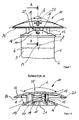
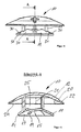
- a weather protection device 10 has a shielding device 11 and a cover device 12 arranged vertically above the shielding device 11.
- the shielding device 11 and the covering device 12 are arranged vertically spaced from each other by means of at least one, preferably a plurality of spacers 13.
- the shielding device 11 is in the embodiment of Figures 1 to 4 thin-walled and truncated cone-shaped with a first outer boundary edge 14 and a second inner boundary edge 15, a top 16 and a bottom 17.
- the outer boundary edge 14 is used in particular latching attachment in the groove.
- a cone angle ⁇ of a cone enclosing the shielding device 11 is obtuse-angled and is 100 ° to 180 °, in particular 120 ° to 150 °.
- the angle ⁇ > 135 ° is selected.
- the second inner boundary edge 15 delimits a central opening 18 in the shielding device 11.
- the shielding device 11 has ventilation openings 19 which penetrate the shielding device 11 so that from the top side 16 toward the interior of the enveloping body 2 Fresh air can flow.
- the spacers 13 are formed as a cross-sectionally U-shaped to the central opening 18 toward open columns and integrally connected to the shielding device 11.
- the spacers 13 which are U-shaped in cross-section open into the central opening 18 and thus increase the possible exhaust gas passage cross-section for the exhaust gases of the candle flame.
- the spacers 13 are integrally connected to the cover 12.
- the cover 12 has a dome-shaped spatial form, z. B. a spherical shell portion-shaped spatial form and is in diameter
- the covering device 12 covers both the central opening 18 and the ventilation openings 19 of the shielding device 11.
- the weather protection device 10 in a particularly advantageous manner, for example as an injection-molded plastic part, it is particularly advantageous that a clear width d between the upper side 16 of the shielding device 11 and a lower side 20 of the cover device 12 at least in the area outside the central opening 18 increases from a central axis 21 to the outside.
- An outer side 22 of the cover 12 is preferably formed smooth surface and may ornaments 23, for example, in the case of a grave light cover crosses. Of course, any other type of ornament on the top 22 of the cover 12 may be mounted.
- FIGS. 5 to 8 A second particularly preferred embodiment of the weather protection device 10 according to the invention is described below with reference to FIGS. 5 to 8.
- the second embodiment has substantially the same basic structure as the above-described first embodiment, so that only the differences from the first embodiment will be explained below.
- the shielding device 11 is also integrally formed and substantially truncated cone-shaped at least in sections, wherein portions 30 each edges 31 are arranged forming successively in the circumferential direction.
- the spacers 13 are arranged, which extend from the shielding device 11 vertically upwards.
- the spacers 13 are solid in the second exemplary embodiment and arranged with respect to the edges 31 such that the edges 31 pass through the cross-sectional profile of the spacers 13 approximately centrally.
- This spatial configuration makes it possible to design the spacers 13 solid and still produce the weather protection device 10 according to the invention in one piece and to demould safely with a sliding tool. Furthermore, it is possible to design or design the central opening 18 with respect to its size (with respect to its diameter d2) independently of the arrangement of the section holders 13. Furthermore, results in the embodiment according to Figures 5 to 8, a visually filigree impression.
- the shielding device 11 is flat-plate-shaped with the central opening 18, wherein the covering device 12 is arranged in the manner of a gable or dome-shaped by means of spacers 13 above the shielding device 11.
- both the cover device 12 and the shielding device 11 may each be dome-shaped or gable-shaped.
- the diameter ratio between the diameter d 2 of the central opening 18 and the outer diameter d 1 of the shielding device 11 is advantageously 1: 4 to 1: 2, preferably 1: 3.
- an outer peripheral edge 24 of the cover device 12 is arranged in the proper use of the weather protection device 10 vertically above the boundary edge 15 of the central opening 18 so that a free passage cross-section 25 for exhaust and / or fresh air (in a side view or in section AA according to Figure 2) is formed. This ensures a reliable discharge of rising exhaust gases, especially in very weak wind or even in calm.
- An angle ⁇ between outer tangents of the cover device 12 is 130 ° to 170 °, in particular 150 ° to 160 °.
- the shielding device 11 is matched in diameter to the enveloping body 2 in such a way that it can be inserted into the groove 7 in a clamping or latching manner.
- the shielding device can also have an inverted collar (not shown) by means of which it can be inserted over the upper edge 6 of the enveloping body 2.
- the weather protection device 10 is formed, for example, of metal, preferably of heat-resistant plastic, in particular of a thermoplastic elastomer (TPE) or a duroplastic. It has proven particularly preferable, at least the cover device 12 form of a transparent or translucent material, so that a shine through the candlelight is visible from above.
- TPE thermoplastic elastomer
- the diameter d 2 of the central opening 18 is 2 cm to 4 cm, in particular 2.5 cm to 3.5 cm, particularly preferably 2.7 cm.
- the weather protection device 10 according to the invention over conventional grave light covers, such. Grave light covers according to DE-GM-86105280, DE-GM-9311551.2, DE-GM-20100017 U1 and DE-GM-8814266 a significant increase in the endurance properties, e.g. a grave candle causes, as both gusts and heavy rainfall, such. Driving rain, does not lead to extinction of the candle flames.
- a free surface 22 of the shielding device 12 is made available, which is freely available for the optical design of the weather protection device 10, without exhibiting optically disturbing supply or discharge openings.
- the weather protection device 10 according to the invention can be produced in one piece in a simple manner in a cost-effective production process, in particular by injection molding. This eliminates all assembly work to assemble the weather protection device 10th
- sharp edges such as sharp metal edges, can be avoided, so that the risk of injury during handling is reduced.
Landscapes
- Engineering & Computer Science (AREA)
- General Engineering & Computer Science (AREA)
- Chemical & Material Sciences (AREA)
- Combustion & Propulsion (AREA)
- Arrangement Of Elements, Cooling, Sealing, Or The Like Of Lighting Devices (AREA)
- Fire-Extinguishing Compositions (AREA)
Applications Claiming Priority (1)
| Application Number | Priority Date | Filing Date | Title |
|---|---|---|---|
| DE200520012663 DE202005012663U1 (de) | 2005-08-11 | 2005-08-11 | Allwetterschutz für Grab- und Partytagebrenner |
Publications (2)
| Publication Number | Publication Date |
|---|---|
| EP1760397A2 true EP1760397A2 (fr) | 2007-03-07 |
| EP1760397A3 EP1760397A3 (fr) | 2008-04-23 |
Family
ID=35433607
Family Applications (1)
| Application Number | Title | Priority Date | Filing Date |
|---|---|---|---|
| EP06014604A Withdrawn EP1760397A3 (fr) | 2005-08-11 | 2006-07-13 | Dispositif de protection contre les intempéries pour bougeoirs, lampes et autres récipients pour bougies |
Country Status (2)
| Country | Link |
|---|---|
| EP (1) | EP1760397A3 (fr) |
| DE (1) | DE202005012663U1 (fr) |
Cited By (2)
| Publication number | Priority date | Publication date | Assignee | Title |
|---|---|---|---|---|
| US20150250159A1 (en) * | 2014-03-06 | 2015-09-10 | Brian D Cole | Multiple scent delivery device |
| AT519550B1 (de) * | 2017-08-04 | 2018-08-15 | Dr Wilfrid Wetzl | Nach oben offener Hohlkörper mit Deckel |
Families Citing this family (1)
| Publication number | Priority date | Publication date | Assignee | Title |
|---|---|---|---|---|
| AT515798B1 (de) * | 2014-06-11 | 2015-12-15 | Nifra Parfümerie Ges M B H Nachfolger Panny Kg | Grabkerze |
Family Cites Families (6)
| Publication number | Priority date | Publication date | Assignee | Title |
|---|---|---|---|---|
| US1693704A (en) * | 1926-08-31 | 1928-12-04 | Watkins Devereux John Gregory | Windproof lamp |
| US1726895A (en) * | 1928-01-06 | 1929-09-03 | Holmstrom Emil | Wind-deflector signal lamp |
| DE2530712A1 (de) * | 1975-07-10 | 1977-01-20 | Georg Keiderling | Verstellbarer zirkulationsregler fuer einsaetze, vasen, behaelter u.dgl. |
| DE2804589A1 (de) * | 1978-02-03 | 1979-08-09 | Klein Gmbh & Co Klebekerzen | Kerzengefaess, in welchem die flamme gegen wind und regen geschuetzt ist |
| AT7702U1 (de) * | 2004-06-25 | 2005-07-25 | Just Fritz Peter | Leuchte mit einem leuchtelement |
| KR100665319B1 (ko) * | 2004-09-20 | 2007-01-04 | 조창현 | 방풍커버가 구비된 휴대용 파라핀오일램프 |
-
2005
- 2005-08-11 DE DE200520012663 patent/DE202005012663U1/de not_active Expired - Lifetime
-
2006
- 2006-07-13 EP EP06014604A patent/EP1760397A3/fr not_active Withdrawn
Cited By (3)
| Publication number | Priority date | Publication date | Assignee | Title |
|---|---|---|---|---|
| US20150250159A1 (en) * | 2014-03-06 | 2015-09-10 | Brian D Cole | Multiple scent delivery device |
| AT519550B1 (de) * | 2017-08-04 | 2018-08-15 | Dr Wilfrid Wetzl | Nach oben offener Hohlkörper mit Deckel |
| AT519550A4 (de) * | 2017-08-04 | 2018-08-15 | Dr Wilfrid Wetzl | Nach oben offener Hohlkörper mit Deckel |
Also Published As
| Publication number | Publication date |
|---|---|
| DE202005012663U1 (de) | 2005-11-17 |
| EP1760397A3 (fr) | 2008-04-23 |
Similar Documents
| Publication | Publication Date | Title |
|---|---|---|
| DE60123957T2 (de) | Brenner mit interner trennung | |
| DE102005027282A1 (de) | Ventilanordnung für Automobilkarosserie | |
| EP0802369B1 (fr) | Boítier de lampe pour lampe d'extérieur, notamment pour lampadaire | |
| DE202017101445U1 (de) | Leuchtenschirm | |
| EP1760397A2 (fr) | Dispositif de protection contre les intempéries pour bougeoirs, lampes et autres récipients pour bougies | |
| DE102012206507A1 (de) | Brenner für ein gasbeheiztes Gargerät | |
| EP4183627A1 (fr) | Assemblage de montage d'un dispositif d'éclairage de véhicule automobile et véhicule automobile | |
| EP3736490B1 (fr) | Dispositif comprenant un corps creux ouvert vers le haut et un couvercle pouvant être enlevé | |
| DE102007004879A1 (de) | Abzugsschacht | |
| DE102005007089B4 (de) | Bauteil zum Einbau in geringem Abstand unter der äußeren Karosseriehaut eines Kraftfahrzeugs | |
| AT525343B1 (de) | Grablicht | |
| DE69406452T2 (de) | Lampenzusammenbau mit ventilationsdurchlass | |
| DE10036312B4 (de) | Heizgerät, insbesondere Kaminofen | |
| AT519550B1 (de) | Nach oben offener Hohlkörper mit Deckel | |
| DE3912913A1 (de) | Leuchtgitterkerze | |
| DE19815493C2 (de) | Schornsteinkopf | |
| EP0322570A1 (fr) | Chapeau pour cheminée | |
| EP2000055A1 (fr) | Siège | |
| DE10135842B4 (de) | Opferlichtständer | |
| DE102008063370A1 (de) | Leuchte | |
| EP0359102B1 (fr) | Chaudière | |
| DE10210955A1 (de) | Leuchte | |
| DE964702C (de) | Zur Aufhaengung bestimmte Leuchte | |
| DE726913C (de) | Schornsteinhaube, insbesondere fuer Laternen und OEfen in Eisenbahnfahrzeugen | |
| DE630355C (de) | Schornsteinoberteil mit einer am oberen Ende geschlossenen Rauchleitung |
Legal Events
| Date | Code | Title | Description |
|---|---|---|---|
| PUAI | Public reference made under article 153(3) epc to a published international application that has entered the european phase |
Free format text: ORIGINAL CODE: 0009012 |
|
| AK | Designated contracting states |
Kind code of ref document: A2 Designated state(s): AT BE BG CH CY CZ DE DK EE ES FI FR GB GR HU IE IS IT LI LT LU LV MC NL PL PT RO SE SI SK TR |
|
| AX | Request for extension of the european patent |
Extension state: AL BA HR MK YU |
|
| PUAL | Search report despatched |
Free format text: ORIGINAL CODE: 0009013 |
|
| AK | Designated contracting states |
Kind code of ref document: A3 Designated state(s): AT BE BG CH CY CZ DE DK EE ES FI FR GB GR HU IE IS IT LI LT LU LV MC NL PL PT RO SE SI SK TR |
|
| AX | Request for extension of the european patent |
Extension state: AL BA HR MK RS |
|
| AKX | Designation fees paid | ||
| STAA | Information on the status of an ep patent application or granted ep patent |
Free format text: STATUS: THE APPLICATION IS DEEMED TO BE WITHDRAWN |
|
| 18D | Application deemed to be withdrawn |
Effective date: 20081024 |
|
| REG | Reference to a national code |
Ref country code: DE Ref legal event code: 8566 |