EP1762331B1 - Broche avec capteur de données lisible par ondes radio - Google Patents
Broche avec capteur de données lisible par ondes radio Download PDFInfo
- Publication number
- EP1762331B1 EP1762331B1 EP05019759A EP05019759A EP1762331B1 EP 1762331 B1 EP1762331 B1 EP 1762331B1 EP 05019759 A EP05019759 A EP 05019759A EP 05019759 A EP05019759 A EP 05019759A EP 1762331 B1 EP1762331 B1 EP 1762331B1
- Authority
- EP
- European Patent Office
- Prior art keywords
- spindle
- read
- radio
- data
- data acquisition
- Prior art date
- Legal status (The legal status is an assumption and is not a legal conclusion. Google has not performed a legal analysis and makes no representation as to the accuracy of the status listed.)
- Expired - Lifetime
Links
Images


Classifications
-
- H—ELECTRICITY
- H04—ELECTRIC COMMUNICATION TECHNIQUE
- H04Q—SELECTING
- H04Q9/00—Arrangements in telecontrol or telemetry systems for selectively calling a substation from a main station, in which substation desired apparatus is selected for applying a control signal thereto or for obtaining measured values therefrom
-
- B—PERFORMING OPERATIONS; TRANSPORTING
- B23—MACHINE TOOLS; METAL-WORKING NOT OTHERWISE PROVIDED FOR
- B23Q—DETAILS, COMPONENTS, OR ACCESSORIES FOR MACHINE TOOLS, e.g. ARRANGEMENTS FOR COPYING OR CONTROLLING; MACHINE TOOLS IN GENERAL CHARACTERISED BY THE CONSTRUCTION OF PARTICULAR DETAILS OR COMPONENTS; COMBINATIONS OR ASSOCIATIONS OF METAL-WORKING MACHINES, NOT DIRECTED TO A PARTICULAR RESULT
- B23Q1/00—Members which are comprised in the general build-up of a form of machine, particularly relatively large fixed members
- B23Q1/0009—Energy-transferring means or control lines for movable machine parts; Control panels or boxes; Control parts
-
- B—PERFORMING OPERATIONS; TRANSPORTING
- B23—MACHINE TOOLS; METAL-WORKING NOT OTHERWISE PROVIDED FOR
- B23Q—DETAILS, COMPONENTS, OR ACCESSORIES FOR MACHINE TOOLS, e.g. ARRANGEMENTS FOR COPYING OR CONTROLLING; MACHINE TOOLS IN GENERAL CHARACTERISED BY THE CONSTRUCTION OF PARTICULAR DETAILS OR COMPONENTS; COMBINATIONS OR ASSOCIATIONS OF METAL-WORKING MACHINES, NOT DIRECTED TO A PARTICULAR RESULT
- B23Q17/00—Arrangements for observing, indicating or measuring on machine tools
-
- B—PERFORMING OPERATIONS; TRANSPORTING
- B23—MACHINE TOOLS; METAL-WORKING NOT OTHERWISE PROVIDED FOR
- B23Q—DETAILS, COMPONENTS, OR ACCESSORIES FOR MACHINE TOOLS, e.g. ARRANGEMENTS FOR COPYING OR CONTROLLING; MACHINE TOOLS IN GENERAL CHARACTERISED BY THE CONSTRUCTION OF PARTICULAR DETAILS OR COMPONENTS; COMBINATIONS OR ASSOCIATIONS OF METAL-WORKING MACHINES, NOT DIRECTED TO A PARTICULAR RESULT
- B23Q5/00—Driving or feeding mechanisms; Control arrangements therefor
- B23Q5/02—Driving main working members
- B23Q5/04—Driving main working members rotary shafts, e.g. working-spindles
-
- H—ELECTRICITY
- H04—ELECTRIC COMMUNICATION TECHNIQUE
- H04Q—SELECTING
- H04Q2209/00—Arrangements in telecontrol or telemetry systems
- H04Q2209/40—Arrangements in telecontrol or telemetry systems using a wireless architecture
- H04Q2209/47—Arrangements in telecontrol or telemetry systems using a wireless architecture using RFID associated with sensors
-
- H—ELECTRICITY
- H04—ELECTRIC COMMUNICATION TECHNIQUE
- H04Q—SELECTING
- H04Q2209/00—Arrangements in telecontrol or telemetry systems
- H04Q2209/80—Arrangements in the sub-station, i.e. sensing device
- H04Q2209/86—Performing a diagnostic of the sensing device
-
- Y—GENERAL TAGGING OF NEW TECHNOLOGICAL DEVELOPMENTS; GENERAL TAGGING OF CROSS-SECTIONAL TECHNOLOGIES SPANNING OVER SEVERAL SECTIONS OF THE IPC; TECHNICAL SUBJECTS COVERED BY FORMER USPC CROSS-REFERENCE ART COLLECTIONS [XRACs] AND DIGESTS
- Y10—TECHNICAL SUBJECTS COVERED BY FORMER USPC
- Y10T—TECHNICAL SUBJECTS COVERED BY FORMER US CLASSIFICATION
- Y10T408/00—Cutting by use of rotating axially moving tool
- Y10T408/16—Cutting by use of rotating axially moving tool with control means energized in response to activator stimulated by condition sensor
-
- Y—GENERAL TAGGING OF NEW TECHNOLOGICAL DEVELOPMENTS; GENERAL TAGGING OF CROSS-SECTIONAL TECHNOLOGIES SPANNING OVER SEVERAL SECTIONS OF THE IPC; TECHNICAL SUBJECTS COVERED BY FORMER USPC CROSS-REFERENCE ART COLLECTIONS [XRACs] AND DIGESTS
- Y10—TECHNICAL SUBJECTS COVERED BY FORMER USPC
- Y10T—TECHNICAL SUBJECTS COVERED BY FORMER US CLASSIFICATION
- Y10T409/00—Gear cutting, milling, or planing
- Y10T409/30—Milling
- Y10T409/30392—Milling with means to protect operative or machine [e.g., guard, safety device, etc.]
-
- Y—GENERAL TAGGING OF NEW TECHNOLOGICAL DEVELOPMENTS; GENERAL TAGGING OF CROSS-SECTIONAL TECHNOLOGIES SPANNING OVER SEVERAL SECTIONS OF THE IPC; TECHNICAL SUBJECTS COVERED BY FORMER USPC CROSS-REFERENCE ART COLLECTIONS [XRACs] AND DIGESTS
- Y10—TECHNICAL SUBJECTS COVERED BY FORMER USPC
- Y10T—TECHNICAL SUBJECTS COVERED BY FORMER US CLASSIFICATION
- Y10T409/00—Gear cutting, milling, or planing
- Y10T409/30—Milling
- Y10T409/30784—Milling including means to adustably position cutter
- Y10T409/307952—Linear adjustment
- Y10T409/308008—Linear adjustment with control for adjustment means responsive to activator stimulated by condition sensor
-
- Y—GENERAL TAGGING OF NEW TECHNOLOGICAL DEVELOPMENTS; GENERAL TAGGING OF CROSS-SECTIONAL TECHNOLOGIES SPANNING OVER SEVERAL SECTIONS OF THE IPC; TECHNICAL SUBJECTS COVERED BY FORMER USPC CROSS-REFERENCE ART COLLECTIONS [XRACs] AND DIGESTS
- Y10—TECHNICAL SUBJECTS COVERED BY FORMER USPC
- Y10T—TECHNICAL SUBJECTS COVERED BY FORMER US CLASSIFICATION
- Y10T409/00—Gear cutting, milling, or planing
- Y10T409/30—Milling
- Y10T409/309352—Cutter spindle or spindle support
-
- Y—GENERAL TAGGING OF NEW TECHNOLOGICAL DEVELOPMENTS; GENERAL TAGGING OF CROSS-SECTIONAL TECHNOLOGIES SPANNING OVER SEVERAL SECTIONS OF THE IPC; TECHNICAL SUBJECTS COVERED BY FORMER USPC CROSS-REFERENCE ART COLLECTIONS [XRACs] AND DIGESTS
- Y10—TECHNICAL SUBJECTS COVERED BY FORMER USPC
- Y10T—TECHNICAL SUBJECTS COVERED BY FORMER US CLASSIFICATION
- Y10T409/00—Gear cutting, milling, or planing
- Y10T409/30—Milling
- Y10T409/309352—Cutter spindle or spindle support
- Y10T409/309408—Cutter spindle or spindle support with cutter holder
- Y10T409/309464—Cutter spindle or spindle support with cutter holder and draw bar
Definitions
- the invention relates to a spindle having the features of the preamble of patent claim 1.
- US 2005/0134436 A1 describes a system for selectively selecting a particular RFID chip from a plurality of RFID chips. There is disclosed that RFID tags that do not have their own power supply, can be powered by radio waves of a read element with energy.
- the invention has for its object to offer a spindle for a machine tool, in the recorded operating and / or state data are particularly advantageous readable. In particular, access to certain data should be limited to specific groups of people.
- a data acquisition element which is designed as a radio chip and can be read out by radio via a read element. This no longer requires a wired connection for reading out the data acquisition element.
- the radio chip has no own power supply and the radio chip is read out corresponding energy supplied via the radio waves of the reader.
- the radio chip can be designed as a passive RFID element (Radio Frequency Identification Detector).
- a read / write device emits electromagnetic waves and thus generates an electromagnetic field (radio transmitter). If an object marked with a special label, a so-called transponder, is located in the electromagnetic field, it behaves as a receiver. The transponder absorbs the energy via an antenna coil (induction) and uses it to send the data stored on a microchip back to the read / write device.
- Passive RFID elements do not have their own energy source and, like the read / write device, work both as a receiver and as a transmitter. The data received by the read / write device in this way can then be forwarded to other computer applications.
- an external reading device is provided which is used by the user of the spindle or by a person responsible for the repair and service of the spindle, brought from outside to the vicinity of the spindle and thus read out in the spindle in radio chips as data acquisition elements the data of the data acquisition element become.
- the spindle has an integrated reading device in order also to read radio chips arranged within the spindle.
- a reading device can thus be provided within the spindle, which communicate via radio waves with likewise within the spindle as a data acquisition element, namely as a radio chip formed elements without its own power supply and read data detected in the radio chips.
- Such wireless data acquisition elements simplify the construction of the spindle and the mounting of the spindle.
- the reading device can be connected to a machine control of the machine tool.
- this can be done wirelessly or wired.
- a connection in particular a cable connection, may be present with the machine control.
- the reading device for reading the radio chip of a particular spindle, in particular the spindle, in which the reading device is integrated can be used. Furthermore, one or more further spindles can be read out via a reading device. This makes it possible to read through a single reader several spindles and the data acquisition elements mounted there. This can be done with little effort, e.g. take place in a machine shop with several machine tools of spindles, a readout of data acquisition elements.
- the radio chip has a data area which can only be read by an external reading device and not by a reading device of the spindle.
- the spindle can be read with their radio chips on the one hand by a spindle-integrated reader, with only a certain range of data is read. Another data area of the radio chip may be detected by a mobile reader of an external person, e.g. is responsible for the service or use.
- the read element may further comprise a plurality of selectable separate radio signals, e.g. on different radio channels, for separate reading of different radio chips within a spindle or the radio chips of several spindles. For this purpose, a connection between the spindle-integrated read element and the machine control of the machine tool can be used to control the read element for selecting the separate radio signals.
- the access to information within the radio chip can be controlled by the machine control or the user of a mobile reading device, and it can be determined which data is accessible to whom.
- a data collection element may store data from the manufacturer of the spindle (e.g., serial number, date of original delivery, warranty information, performance data, power / torque and speed history, parameter sets for CNC control, etc.) and read it out at the service site.
- data from the manufacturer of the spindle e.g., serial number, date of original delivery, warranty information, performance data, power / torque and speed history, parameter sets for CNC control, etc.
- last state data could be stored before a failure (for this purpose, if necessary, an active RFID with its own power supply can be used).
- Users e.g., the end customer
- the spindle may generally have readers for the RFID elements of the spindle and thus use e.g. transmit to the spindle manufacturer via the Internet additional data for remote diagnostics. Then data would not have to be constantly exchanged, but only in case of need.
- the end customer could also use an RFID element for data exchange with the spindle manufacturer, i. the place of use and the machine number could be noted by the end customer on the RFID element.
- the spindle manufacturer could identify fault priorities and machine problems for the end customer at an early stage and point out that the customer's factory maintenance focuses on these fault focuses.
- the spindle can also be provided with two or more RFID elements, an RFID device only for the internal data of the spindle manufacturer (first data area - not rewritable) and one or more RFID elements that can be overwritten by end customers and spindle manufacturers.
- a single RFID element may also have a first rewritable data area and a second non-rewritable data area.
- RFID elements with the corresponding data can be installed.
- the storage location and production status of this spindle could then be automatically recorded and used accordingly for shipping and sales processing.
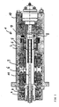
- Fig. 1 shows a schematic sectional view of a known per se spindle 1 with a housing 2 in which an electric motor 3 is accommodated, which drives a recorded in the bearings 4 and 5 shaft 6 with clamping element 7 for receiving a tool not shown.
- the spindle 1 has an integrated into the shaft 6 or on this example circumferentially mounted data collection element 8, which are formed as a radio chip.
- the rotating data acquisition elements 8 can be read by a reader 9 of the spindle 1 (unidirectional and / or bidirectional, ie pure readout of the data acquisition element 8 and / or write data acquisition element 8 with integrated memory).
- the reader 9 is connected, for example, wired with another element 10 for data processing and / or storage, which may have an interface to the machine control, not shown, of the machine tool.
- the data acquisition element 8 does not have its own power supply and is read out by the reading device 9 providing the energy required for the data acquisition element 8 with the radio waves emitted.
- a wireless data acquisition element 8 can be attached to components connected to wired elements e.g. can not be reached due to the rotation of the component or the space required.
- data such as the engine temperature, storage temperature and / or the clamping state can be used by the data acquisition element 8 (Determine the position of the drawbar 11 within the shaft 6, tensioned or non-tensioned).
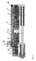
- Fig. 2a shows another reader 9 ', which in the stator 12 (eg in the winding head) of the electric motor 3 a spindle 1 after Fig.1 is integrated.
- a corresponding readable data acquisition element 8 ' (eg for temperature data) can be integrated into the rotor 15 of the electric motor 3 and rotate therewith.
- a further reading device 9 can be provided, which is arranged outside of the stator 13 within the housing 2 of the spindle 1.
- Fig. 2b shows further possibilities of integration of another reader 9, for example, in the stationary outer ring 15 of a bearing 4 or 5, while in the rotating inner ring 16 of the bearing 4 or 5, a further data acquisition element 8 is provided.
- Fig. 2c can also be another reader 9 is provided in the stationary housing 2 of the spindle 1, which has a radio link to another data acquisition element 8 in a rotating inner ring 16 of a bearing 4 or 5.
- Fig. 3 shows a further possibility of attaching a reader 9, which is mounted in a first assembly of the spindle 1 (eg, the housing 2), which is detachably connectable to a second assembly of the spindle 1.
- a reader 9 which is mounted in a first assembly of the spindle 1 (eg, the housing 2), which is detachably connectable to a second assembly of the spindle 1.
- the second assembly (here a bearing cap) has a data acquisition element 8. This can across the border 18 of several modules across a communication or a readout of data between reader 9 and data acquisition element 8 take place wirelessly.
- the assembly and disassembly of the spindle 1 is facilitated, eliminating solder joints, connectors and fitting of cable connections. This eliminates the risk of cable breaks or unintentional ground faults. It is a trouble-free data transmission via radio within the spindle 1 allows.
- Fig. 4 shows a recorded in a machine tool 21 spindle 1 with housing 2 with data acquisition element 8.
- a mobile reader 9 " which is used by a person eg for the control, the service or the monitoring of the spindle 1, the reader 9" in the vicinity of the spindle 1 are spent and read within the spindle 1 existing data acquisition elements 8 by radio.
- a plurality of radio chips within a spindle 1 can be read out. Furthermore, several different spindles 1 can be read with different radio chips.
- This mobile reader can be used by the user as a manual version. Furthermore, in the working space of the spindle 1 (eg in a machine shop), such an external reading device 9 "can be mounted and the radio chips recorded in the spindles regularly read out for further evaluation, for example in a machine center.
Landscapes
- Engineering & Computer Science (AREA)
- Mechanical Engineering (AREA)
- Computer Networks & Wireless Communication (AREA)
- Arrangements For Transmission Of Measured Signals (AREA)
- Machine Tool Sensing Apparatuses (AREA)
- Turning (AREA)
- Control Of Stepping Motors (AREA)
- Slot Machines And Peripheral Devices (AREA)
- Numerical Control (AREA)
Claims (6)
- Broche pour une machine-outil, notamment broche motorisée comprenant une boîtier (2) pour recevoir une moteur électrique (3) et un arbre (6) pouvant être entraîné par celui-ci, notamment avec un attachement d'outil pour un outil destiné à l'usinage de pièces, au moins un élément d'acquisition de données (8, 8') étant prévu pour collecter des données de fonctionnement et/ou d'état de la broche (1) ainsi qu'un lecteur (9'') externe pour lire l'élément d'acquisition de données (8, 8'),
caractérisée en ce que- l'élément d'acquisition de données (8, 8') est réalisé sous la forme d'une puce radioélectrique et peut être lu par voie radioélectrique par le lecteur externe (9''),- la broche (1) présente un élément de lecture (9 9') intégré pour lire une puce radioélectrique à l'intérieur de la broche (1) et- la broche (1) présente plusieurs puces radioélectriques qui peuvent être lues en partie par l'élément de lecture interne (9, 9') et en partie par le lecteur externe (9''). - Broche selon la revendication 1, caractérisée en ce que la puce radioélectrique ne présente pas de source d'énergie propre et l'énergie correspondante est acheminée à la puce radioélectrique lors de la lecture par le biais des ondes radioélectriques de l'élément de lecture (9, 9', 9'').
- Broche selon l'une des revendications précédentes, caractérisée en ce que l'élément de lecture (9, 9', 9'') peut être relié avec une commande de machine de la machine-outil (19).
- Broche selon l'une des revendications précédentes, caractérisée en ce que l'élément de lecture (9, 9', 9'') est prévu pour lire la puce radioélectrique de la même broche (1) et pour lire les puces radioélectriques des broches voisines.
- Broche selon la revendication 1, caractérisée en ce que la puce radioélectrique présente une zone de données qui peut seulement être lue par l'élément de lecture externe (9'') et pas par l'élément de lecture intégré (9, 9') de la broche.
- Broche selon l'une des revendications précédentes, caractérisée en ce que l'élément de lecture (9, 9', 9'') présente plusieurs signaux radioélectriques séparables au choix pour la lecture séparée de différentes puces radioélectriques.
Priority Applications (12)
| Application Number | Priority Date | Filing Date | Title |
|---|---|---|---|
| ES05019759T ES2320236T3 (es) | 2005-09-12 | 2005-09-12 | Portaherramientas con un elemento de captacion de datos legible por ondas de radio. |
| ES08168499T ES2426367T3 (es) | 2005-09-12 | 2005-09-12 | Portaherramientas con un elemento de captación de datos legible por ondas de radio |
| DE502005006336T DE502005006336D1 (de) | 2005-09-12 | 2005-09-12 | Spindel mit einem per Funk auslesbaren Datenerfassungselement |
| AT05019759T ATE418416T1 (de) | 2005-09-12 | 2005-09-12 | Spindel mit einem per funk auslesbaren datenerfassungselement |
| EP05019759A EP1762331B1 (fr) | 2005-09-12 | 2005-09-12 | Broche avec capteur de données lisible par ondes radio |
| EP08168499.5A EP2025445B1 (fr) | 2005-09-12 | 2005-09-12 | Broche dotée d'un élément de saisie de données |
| US11/991,717 US8083446B2 (en) | 2005-09-12 | 2006-08-11 | Spindle having a data acquisition element which can be read by a radio |
| CN2006800334788A CN101374633B (zh) | 2005-09-12 | 2006-08-11 | 具有可用无线电读取的数据采集元件的主轴 |
| JP2008530313A JP5210869B2 (ja) | 2005-09-12 | 2006-08-11 | 無線で読み出し可能なデータ収集要素を備えた主軸 |
| PCT/DE2006/001404 WO2007031048A1 (fr) | 2005-09-12 | 2006-08-11 | Broche comportant un element de detection de donnees a lecture radio |
| DE112006003125T DE112006003125A5 (de) | 2005-09-12 | 2006-08-11 | Spindel mit einem per Funk auslesbaren Datenerfassungselement |
| TW095131354A TWI379733B (en) | 2005-09-12 | 2006-08-25 | Spindel having a data acquisition element |
Applications Claiming Priority (1)
| Application Number | Priority Date | Filing Date | Title |
|---|---|---|---|
| EP05019759A EP1762331B1 (fr) | 2005-09-12 | 2005-09-12 | Broche avec capteur de données lisible par ondes radio |
Related Child Applications (1)
| Application Number | Title | Priority Date | Filing Date |
|---|---|---|---|
| EP08168499.5A Division EP2025445B1 (fr) | 2005-09-12 | 2005-09-12 | Broche dotée d'un élément de saisie de données |
Publications (2)
| Publication Number | Publication Date |
|---|---|
| EP1762331A1 EP1762331A1 (fr) | 2007-03-14 |
| EP1762331B1 true EP1762331B1 (fr) | 2008-12-24 |
Family
ID=35844056
Family Applications (2)
| Application Number | Title | Priority Date | Filing Date |
|---|---|---|---|
| EP08168499.5A Expired - Lifetime EP2025445B1 (fr) | 2005-09-12 | 2005-09-12 | Broche dotée d'un élément de saisie de données |
| EP05019759A Expired - Lifetime EP1762331B1 (fr) | 2005-09-12 | 2005-09-12 | Broche avec capteur de données lisible par ondes radio |
Family Applications Before (1)
| Application Number | Title | Priority Date | Filing Date |
|---|---|---|---|
| EP08168499.5A Expired - Lifetime EP2025445B1 (fr) | 2005-09-12 | 2005-09-12 | Broche dotée d'un élément de saisie de données |
Country Status (9)
| Country | Link |
|---|---|
| US (1) | US8083446B2 (fr) |
| EP (2) | EP2025445B1 (fr) |
| JP (1) | JP5210869B2 (fr) |
| CN (1) | CN101374633B (fr) |
| AT (1) | ATE418416T1 (fr) |
| DE (2) | DE502005006336D1 (fr) |
| ES (2) | ES2426367T3 (fr) |
| TW (1) | TWI379733B (fr) |
| WO (1) | WO2007031048A1 (fr) |
Cited By (1)
| Publication number | Priority date | Publication date | Assignee | Title |
|---|---|---|---|---|
| US10967434B2 (en) | 2016-08-12 | 2021-04-06 | Big Kaiser Präzisionswerkzeuge Ag | Boring head with an electronic unit |
Families Citing this family (15)
| Publication number | Priority date | Publication date | Assignee | Title |
|---|---|---|---|---|
| DE102010003338A1 (de) | 2010-03-26 | 2011-09-29 | Komet Group Gmbh | Werkzeugmaschine mit Drehübertrager für Daten |
| DE102011017808A1 (de) * | 2011-04-29 | 2012-10-31 | Homag Holzbearbeitungssysteme Gmbh | Spindelsteuerung |
| US9222507B2 (en) * | 2011-12-20 | 2015-12-29 | Aktiebolaget Skf | Method for monitoring a health status of a bearing with a warning device having a close range wireless interface |
| US9284987B2 (en) * | 2011-12-20 | 2016-03-15 | Aktiebolaget Skf | Warning device for monitoring a health status of a bearing having a close range wireless interface |
| DE102012001772B4 (de) | 2012-01-31 | 2024-04-25 | Diehl Metering Systems Gmbh | Funkmodul, insbesondere Erfassungseinrichtung zum Ermitteln und Übermitteln von Verbrauchsdaten |
| EP2735400B1 (fr) * | 2012-11-22 | 2023-03-01 | Sandvik Intellectual Property AB | Agencement permettant de commander le processus d'usinage d'enlèvement rotatif de copeaux d'une pièce et outil de coupe pour usinage par enlèvement de copeaux rotatif |
| DE102016001745B4 (de) | 2016-02-10 | 2021-03-04 | Michael Weinig Ag | Holzbearbeitungs-Werkzeugspindel und Kehlmaschine mit einer solchen Werkzeugspindel |
| DE212018000196U1 (de) | 2017-04-12 | 2019-11-14 | Martin Böni | Bearbeitungsspindel |
| DE102017005068A1 (de) * | 2017-05-20 | 2018-11-22 | Michael Weinig Ag | Temperatur-Überwachungseinrichtung für Werkzeugspindeln von Holzbearbeitungsmaschinen, vorzugsweise Kehlmaschinen, Holzbearbeitungsmaschinen mit einer solchen Temperatur- Überwachungseinrichtung sowie Verfahren unter Verwendung einer Temperatur-Überwachungseinrichtung |
| CN108746675A (zh) * | 2018-08-22 | 2018-11-06 | 河南理工大学 | 基于水冷方式的双路循环冷却超声电主轴传动装置 |
| DE102018007905A1 (de) * | 2018-10-08 | 2020-04-09 | Günther Zimmer | Arbeitsspindel mit Sensoren und Verfahren zur Erfassung und Überwachung ihrer Historie |
| CN110722403A (zh) * | 2019-10-29 | 2020-01-24 | 华中科技大学 | 一种基于电磁感应和射频识别技术的刀具状态监测系统 |
| DE102020112387A1 (de) | 2020-05-07 | 2021-11-11 | Myomega Systems Gmbh | Verfahren zur verschleisserkennung von maschinenwerkzeugen |
| DE202023104806U1 (de) * | 2023-08-24 | 2024-11-26 | Paul Müller GmbH & Co. KG Unternehmensbeteiligungen | Einheit zur Datenerfassung und -verarbeitung für einen Antriebsmotor einer Werkzeugmaschine und Motorspindel |
| EP4537975A1 (fr) | 2023-10-12 | 2025-04-16 | GF Machining Solutions AG | Broche pour machine-outil |
Citations (1)
| Publication number | Priority date | Publication date | Assignee | Title |
|---|---|---|---|---|
| US20050134436A1 (en) * | 2003-12-19 | 2005-06-23 | George Brookner | Multiple RFID anti-collision interrogation method |
Family Cites Families (15)
| Publication number | Priority date | Publication date | Assignee | Title |
|---|---|---|---|---|
| DE1954643A1 (de) * | 1968-11-05 | 1970-06-25 | Lehoczky Dipl Ing Kalman | Einrichtung zur Messwertuebertragung zwischen gegeneinander-rotierenden Systemen |
| FR2582126A1 (fr) * | 1985-05-15 | 1986-11-21 | Salou Alain | Dispositif permettant de " recevoir " sans contact par influence magnetique une information |
| DE3600466A1 (de) * | 1986-01-10 | 1987-07-16 | Otto Zettl | Spannfutter fuer rotierende werkzeuge |
| DE19738229A1 (de) * | 1997-09-02 | 1999-03-04 | Bilz Otto Werkzeug | Werkzeug oder Werkzeughalter |
| DE19741384A1 (de) * | 1997-09-19 | 1999-03-25 | Heuft Systemtechnik Gmbh | Verfahren zum Erkennen von diffus streuenden Materialien, Verunreinigungen und sonstigen Fehlern bei transparenten Gegenständen |
| US6100990A (en) * | 1999-06-14 | 2000-08-08 | Ford Motor Company | Method and apparatus for determining reflective optical quality using gray-scale patterns |
| DE10007126B4 (de) * | 2000-02-17 | 2006-06-22 | Paul Müller GmbH & Co. KG Unternehmensbeteiligungen | Spindel mit einem Datenspeicherelement |
| US6424414B1 (en) * | 2000-10-16 | 2002-07-23 | Agr International, Inc. | Method and apparatus for detecting refractive defects in transparent containers |
| US7011631B2 (en) | 2003-01-21 | 2006-03-14 | Hemonix, Inc. | Noninvasive method of measuring blood density and hematocrit |
| JP2004291118A (ja) * | 2003-03-26 | 2004-10-21 | Incs Inc | 切削加工機用制御装置および方法 |
| JP2004348496A (ja) * | 2003-05-23 | 2004-12-09 | Hitachi Ltd | 通信システム |
| DE10335035A1 (de) * | 2003-08-01 | 2005-03-03 | Siemens Ag | System und Verfahren zur Identifizierung von Automatisierungskomponenten |
| JP2005032256A (ja) * | 2004-07-09 | 2005-02-03 | Ntn Corp | Icタグ・センサユニット |
| DE102004051145C5 (de) * | 2004-10-20 | 2021-03-18 | Marposs Monitoring Solutions Gmbh | Sensorsystem für eine spanabhebende Werkzeugmaschine und spanabhebende Werkzeugmaschine mit einem Sensorsystem |
| DE102006030834B4 (de) * | 2006-07-04 | 2009-11-26 | ARTIS Gesellschaft für angewandte Meßtechnik mbH | Sensorsystem für Werkzeugmaschinen |
-
2005
- 2005-09-12 ES ES08168499T patent/ES2426367T3/es not_active Expired - Lifetime
- 2005-09-12 EP EP08168499.5A patent/EP2025445B1/fr not_active Expired - Lifetime
- 2005-09-12 AT AT05019759T patent/ATE418416T1/de active
- 2005-09-12 DE DE502005006336T patent/DE502005006336D1/de not_active Expired - Lifetime
- 2005-09-12 EP EP05019759A patent/EP1762331B1/fr not_active Expired - Lifetime
- 2005-09-12 ES ES05019759T patent/ES2320236T3/es not_active Expired - Lifetime
-
2006
- 2006-08-11 DE DE112006003125T patent/DE112006003125A5/de not_active Withdrawn
- 2006-08-11 US US11/991,717 patent/US8083446B2/en not_active Expired - Fee Related
- 2006-08-11 JP JP2008530313A patent/JP5210869B2/ja not_active Expired - Fee Related
- 2006-08-11 WO PCT/DE2006/001404 patent/WO2007031048A1/fr not_active Ceased
- 2006-08-11 CN CN2006800334788A patent/CN101374633B/zh not_active Expired - Fee Related
- 2006-08-25 TW TW095131354A patent/TWI379733B/zh not_active IP Right Cessation
Patent Citations (1)
| Publication number | Priority date | Publication date | Assignee | Title |
|---|---|---|---|---|
| US20050134436A1 (en) * | 2003-12-19 | 2005-06-23 | George Brookner | Multiple RFID anti-collision interrogation method |
Cited By (1)
| Publication number | Priority date | Publication date | Assignee | Title |
|---|---|---|---|---|
| US10967434B2 (en) | 2016-08-12 | 2021-04-06 | Big Kaiser Präzisionswerkzeuge Ag | Boring head with an electronic unit |
Also Published As
| Publication number | Publication date |
|---|---|
| EP1762331A1 (fr) | 2007-03-14 |
| ES2320236T3 (es) | 2009-05-20 |
| ES2426367T3 (es) | 2013-10-22 |
| ATE418416T1 (de) | 2009-01-15 |
| EP2025445A2 (fr) | 2009-02-18 |
| US20090267429A1 (en) | 2009-10-29 |
| WO2007031048A8 (fr) | 2008-06-12 |
| EP2025445B1 (fr) | 2013-05-29 |
| JP2009507663A (ja) | 2009-02-26 |
| DE112006003125A5 (de) | 2008-08-28 |
| DE502005006336D1 (de) | 2009-02-05 |
| CN101374633A (zh) | 2009-02-25 |
| TW200718505A (en) | 2007-05-16 |
| US8083446B2 (en) | 2011-12-27 |
| EP2025445A3 (fr) | 2009-02-25 |
| JP5210869B2 (ja) | 2013-06-12 |
| WO2007031048A1 (fr) | 2007-03-22 |
| CN101374633B (zh) | 2011-04-20 |
| TWI379733B (en) | 2012-12-21 |
Similar Documents
| Publication | Publication Date | Title |
|---|---|---|
| EP1762331B1 (fr) | Broche avec capteur de données lisible par ondes radio | |
| EP1255627B1 (fr) | Broche munie d'un element de stockage de donnees | |
| EP2552641B1 (fr) | Machine-outil avec transmetteur rotatif pour des données | |
| DE102012017376B4 (de) | Werkzeug und Verfahren zu dessen Betrieb | |
| DE102010056524B4 (de) | Tragbares Werkzeug und Verfahren zum Durchführen von Arbeitsvorgängen mit diesem Werkzeug | |
| EP1902817A2 (fr) | Outil électrique sans fil et système de fabrication | |
| EP3738703B1 (fr) | Procédé de fonctionnement d'une carotteuse ainsi que carotteuse et couronne de carottage destinées à la mise en oeuvre dudit procédé | |
| WO2014206611A1 (fr) | Système pour détecter des composants d'un véhicule | |
| DE102012103245A1 (de) | Vereinfachte Inbetriebnahme von Antrieben mit individuellen Motordaten | |
| WO2003017015A1 (fr) | Procede d'identification de modules ou d'unites modulaires et systeme d'identification et/ou de diagnostic d'un module ou d'une unite modulaire comprenant une pluralite de composants individuels | |
| EP3455683B1 (fr) | Système et procédé pour traiter des données relatives à un outil | |
| EP2707211B1 (fr) | Procédé de fonctionnement d'une installation de production de comprimés | |
| WO2001043904A1 (fr) | Mecanisme d'entrainement d'outil destine a des machines-outils | |
| DE102006020446A1 (de) | Bearbeitungswerkzeug für ein Werkstück, Bearbeitungsmaschine mit mindestens einem derartigen Bearbeitungswerkzeug sowie mit einer solchen Bearbeitungsmaschine durchgeführtes Bearbeitungsverfahren | |
| EP2995429A1 (fr) | Agencement et son procede de fonctionnement | |
| DE212018000196U1 (de) | Bearbeitungsspindel | |
| EP3994535A1 (fr) | Système de communication et dispositif de machine | |
| EP4371229A1 (fr) | Système d'entraînement comprenant un entraînement alimenté par un convertisseur, et procédé de fonctionnement d'un système d'entraînement | |
| EP3640911A2 (fr) | Procédé pour un équipement ultérieur d'une machine de production avec une fonctionnalité de capteur | |
| DE10341218A1 (de) | Empfangsstation, Messsensor sowie Messsystem mit einer Empfangsstation und einem Messsensor | |
| CH719448A2 (de) | Verfahren für das Datenmanagement insbesondere von Betriebsmitteln einer Werkzeugmaschine sowie Betriebsmittel und Werkzeugmaschine für die Durchführung des Verfahrens. | |
| EP3640755A1 (fr) | Dispositif de mise à niveau d'une fonctionnalité de capteur dans une machine de production | |
| DE102017105726A1 (de) | Drehübertrager für Werkzeugmaschinen | |
| EP2098162A1 (fr) | Dispositif et procédé destinés à l'analyse de composants de machines | |
| DE102007051227A1 (de) | Elektrische Direktantriebsvorrichtung |
Legal Events
| Date | Code | Title | Description |
|---|---|---|---|
| PUAI | Public reference made under article 153(3) epc to a published international application that has entered the european phase |
Free format text: ORIGINAL CODE: 0009012 |
|
| 17P | Request for examination filed |
Effective date: 20060712 |
|
| AK | Designated contracting states |
Kind code of ref document: A1 Designated state(s): AT BE BG CH CY CZ DE DK EE ES FI FR GB GR HU IE IS IT LI LT LU LV MC NL PL PT RO SE SI SK TR |
|
| AX | Request for extension of the european patent |
Extension state: AL BA HR MK YU |
|
| AKX | Designation fees paid |
Designated state(s): AT BE BG CH CY CZ DE DK EE ES FI FR GB GR HU IE IS IT LI LT LU LV MC NL PL PT RO SE SI SK TR |
|
| GRAP | Despatch of communication of intention to grant a patent |
Free format text: ORIGINAL CODE: EPIDOSNIGR1 |
|
| GRAS | Grant fee paid |
Free format text: ORIGINAL CODE: EPIDOSNIGR3 |
|
| GRAA | (expected) grant |
Free format text: ORIGINAL CODE: 0009210 |
|
| AK | Designated contracting states |
Kind code of ref document: B1 Designated state(s): AT BE BG CH CY CZ DE DK EE ES FI FR GB GR HU IE IS IT LI LT LU LV MC NL PL PT RO SE SI SK TR |
|
| REG | Reference to a national code |
Ref country code: GB Ref legal event code: FG4D Free format text: NOT ENGLISH |
|
| REG | Reference to a national code |
Ref country code: CH Ref legal event code: EP |
|
| REG | Reference to a national code |
Ref country code: IE Ref legal event code: FG4D Free format text: LANGUAGE OF EP DOCUMENT: GERMAN |
|
| REF | Corresponds to: |
Ref document number: 502005006336 Country of ref document: DE Date of ref document: 20090205 Kind code of ref document: P |
|
| REG | Reference to a national code |
Ref country code: CH Ref legal event code: NV Representative=s name: SUSI PRYDE-HAENI BSC |
|
| REG | Reference to a national code |
Ref country code: SE Ref legal event code: TRGR |
|
| PG25 | Lapsed in a contracting state [announced via postgrant information from national office to epo] |
Ref country code: LT Free format text: LAPSE BECAUSE OF FAILURE TO SUBMIT A TRANSLATION OF THE DESCRIPTION OR TO PAY THE FEE WITHIN THE PRESCRIBED TIME-LIMIT Effective date: 20081224 |
|
| REG | Reference to a national code |
Ref country code: ES Ref legal event code: FG2A Ref document number: 2320236 Country of ref document: ES Kind code of ref document: T3 |
|
| PG25 | Lapsed in a contracting state [announced via postgrant information from national office to epo] |
Ref country code: FI Free format text: LAPSE BECAUSE OF FAILURE TO SUBMIT A TRANSLATION OF THE DESCRIPTION OR TO PAY THE FEE WITHIN THE PRESCRIBED TIME-LIMIT Effective date: 20081224 Ref country code: LV Free format text: LAPSE BECAUSE OF FAILURE TO SUBMIT A TRANSLATION OF THE DESCRIPTION OR TO PAY THE FEE WITHIN THE PRESCRIBED TIME-LIMIT Effective date: 20081224 Ref country code: NL Free format text: LAPSE BECAUSE OF FAILURE TO SUBMIT A TRANSLATION OF THE DESCRIPTION OR TO PAY THE FEE WITHIN THE PRESCRIBED TIME-LIMIT Effective date: 20081224 Ref country code: PL Free format text: LAPSE BECAUSE OF FAILURE TO SUBMIT A TRANSLATION OF THE DESCRIPTION OR TO PAY THE FEE WITHIN THE PRESCRIBED TIME-LIMIT Effective date: 20081224 Ref country code: SI Free format text: LAPSE BECAUSE OF FAILURE TO SUBMIT A TRANSLATION OF THE DESCRIPTION OR TO PAY THE FEE WITHIN THE PRESCRIBED TIME-LIMIT Effective date: 20081224 |
|
| NLV1 | Nl: lapsed or annulled due to failure to fulfill the requirements of art. 29p and 29m of the patents act | ||
| REG | Reference to a national code |
Ref country code: IE Ref legal event code: FD4D |
|
| PG25 | Lapsed in a contracting state [announced via postgrant information from national office to epo] |
Ref country code: EE Free format text: LAPSE BECAUSE OF FAILURE TO SUBMIT A TRANSLATION OF THE DESCRIPTION OR TO PAY THE FEE WITHIN THE PRESCRIBED TIME-LIMIT Effective date: 20081224 Ref country code: RO Free format text: LAPSE BECAUSE OF FAILURE TO SUBMIT A TRANSLATION OF THE DESCRIPTION OR TO PAY THE FEE WITHIN THE PRESCRIBED TIME-LIMIT Effective date: 20081224 Ref country code: BG Free format text: LAPSE BECAUSE OF FAILURE TO SUBMIT A TRANSLATION OF THE DESCRIPTION OR TO PAY THE FEE WITHIN THE PRESCRIBED TIME-LIMIT Effective date: 20090324 Ref country code: IE Free format text: LAPSE BECAUSE OF FAILURE TO SUBMIT A TRANSLATION OF THE DESCRIPTION OR TO PAY THE FEE WITHIN THE PRESCRIBED TIME-LIMIT Effective date: 20081224 |
|
| PG25 | Lapsed in a contracting state [announced via postgrant information from national office to epo] |
Ref country code: IS Free format text: LAPSE BECAUSE OF FAILURE TO SUBMIT A TRANSLATION OF THE DESCRIPTION OR TO PAY THE FEE WITHIN THE PRESCRIBED TIME-LIMIT Effective date: 20090424 Ref country code: PT Free format text: LAPSE BECAUSE OF FAILURE TO SUBMIT A TRANSLATION OF THE DESCRIPTION OR TO PAY THE FEE WITHIN THE PRESCRIBED TIME-LIMIT Effective date: 20090525 Ref country code: CZ Free format text: LAPSE BECAUSE OF FAILURE TO SUBMIT A TRANSLATION OF THE DESCRIPTION OR TO PAY THE FEE WITHIN THE PRESCRIBED TIME-LIMIT Effective date: 20081224 |
|
| PLBI | Opposition filed |
Free format text: ORIGINAL CODE: 0009260 |
|
| PG25 | Lapsed in a contracting state [announced via postgrant information from national office to epo] |
Ref country code: SK Free format text: LAPSE BECAUSE OF FAILURE TO SUBMIT A TRANSLATION OF THE DESCRIPTION OR TO PAY THE FEE WITHIN THE PRESCRIBED TIME-LIMIT Effective date: 20081224 |
|
| 26 | Opposition filed |
Opponent name: SIEMENS AG CT IP DT 2 Effective date: 20090909 |
|
| PLAX | Notice of opposition and request to file observation + time limit sent |
Free format text: ORIGINAL CODE: EPIDOSNOBS2 |
|
| PG25 | Lapsed in a contracting state [announced via postgrant information from national office to epo] |
Ref country code: DK Free format text: LAPSE BECAUSE OF FAILURE TO SUBMIT A TRANSLATION OF THE DESCRIPTION OR TO PAY THE FEE WITHIN THE PRESCRIBED TIME-LIMIT Effective date: 20081224 |
|
| PLBB | Reply of patent proprietor to notice(s) of opposition received |
Free format text: ORIGINAL CODE: EPIDOSNOBS3 |
|
| BERE | Be: lapsed |
Owner name: PAUL MULLER G.M.B.H. & CO. KG UNTERNEHMENSBETEILI Effective date: 20090930 |
|
| PG25 | Lapsed in a contracting state [announced via postgrant information from national office to epo] |
Ref country code: MC Free format text: LAPSE BECAUSE OF NON-PAYMENT OF DUE FEES Effective date: 20090930 |
|
| PG25 | Lapsed in a contracting state [announced via postgrant information from national office to epo] |
Ref country code: BE Free format text: LAPSE BECAUSE OF NON-PAYMENT OF DUE FEES Effective date: 20090930 |
|
| PG25 | Lapsed in a contracting state [announced via postgrant information from national office to epo] |
Ref country code: GR Free format text: LAPSE BECAUSE OF FAILURE TO SUBMIT A TRANSLATION OF THE DESCRIPTION OR TO PAY THE FEE WITHIN THE PRESCRIBED TIME-LIMIT Effective date: 20090325 |
|
| RDAF | Communication despatched that patent is revoked |
Free format text: ORIGINAL CODE: EPIDOSNREV1 |
|
| PG25 | Lapsed in a contracting state [announced via postgrant information from national office to epo] |
Ref country code: LU Free format text: LAPSE BECAUSE OF NON-PAYMENT OF DUE FEES Effective date: 20090912 |
|
| RDAG | Patent revoked |
Free format text: ORIGINAL CODE: 0009271 |
|
| PLCK | Communication despatched that opposition was rejected |
Free format text: ORIGINAL CODE: EPIDOSNREJ1 |
|
| RDAE | Information deleted related to despatch of communication that patent is revoked |
Free format text: ORIGINAL CODE: EPIDOSDREV1 |
|
| REG | Reference to a national code |
Ref country code: CH Ref legal event code: PL |
|
| PLBN | Opposition rejected |
Free format text: ORIGINAL CODE: 0009273 |
|
| RDAC | Information related to revocation of patent modified |
Free format text: ORIGINAL CODE: 0009299REVO |
|
| 27W | Patent revoked |
Effective date: 20110204 |
|
| GBPR | Gb: patent revoked under art. 102 of the ep convention designating the uk as contracting state |
Effective date: 20110204 |
|
| PG25 | Lapsed in a contracting state [announced via postgrant information from national office to epo] |
Ref country code: HU Free format text: LAPSE BECAUSE OF FAILURE TO SUBMIT A TRANSLATION OF THE DESCRIPTION OR TO PAY THE FEE WITHIN THE PRESCRIBED TIME-LIMIT Effective date: 20090625 |
|
| 27O | Opposition rejected |
Effective date: 20110204 |
|
| D27W | Patent revoked (deleted) | ||
| PG25 | Lapsed in a contracting state [announced via postgrant information from national office to epo] |
Ref country code: LI Free format text: LAPSE BECAUSE OF THE APPLICANT RENOUNCES Effective date: 20081224 Ref country code: CH Free format text: LAPSE BECAUSE OF THE APPLICANT RENOUNCES Effective date: 20081224 |
|
| REG | Reference to a national code |
Ref country code: AT Ref legal event code: EELB Ref document number: AT T Free format text: BERICHTIGER WIDERRUF MIT WIRKUNG VON 20081224. PATENT IST WIEDER AUFRECHT |
|
| REG | Reference to a national code |
Ref country code: SE Ref legal event code: ECNC |
|
| PG25 | Lapsed in a contracting state [announced via postgrant information from national office to epo] |
Ref country code: TR Free format text: LAPSE BECAUSE OF FAILURE TO SUBMIT A TRANSLATION OF THE DESCRIPTION OR TO PAY THE FEE WITHIN THE PRESCRIBED TIME-LIMIT Effective date: 20081224 |
|
| PG25 | Lapsed in a contracting state [announced via postgrant information from national office to epo] |
Ref country code: CY Free format text: LAPSE BECAUSE OF FAILURE TO SUBMIT A TRANSLATION OF THE DESCRIPTION OR TO PAY THE FEE WITHIN THE PRESCRIBED TIME-LIMIT Effective date: 20081224 |
|
| REG | Reference to a national code |
Ref country code: CH Ref legal event code: AEN Free format text: REAKTIVIERUNG NACH IRRTUEMLICHER LOESCHUNG Ref country code: CH Ref legal event code: PK Free format text: DER WIDERRUF DES PATENTS WURDE DURCH DAS EPA AUFGEHOBEN. |
|
| PLAE | Information related to rejection of opposition modified |
Free format text: ORIGINAL CODE: 0009299REJO |
|
| STAA | Information on the status of an ep patent application or granted ep patent |
Free format text: STATUS: OPPOSITION REJECTED |
|
| R27O | Information related to the rejection of opposition modified: opposition rejected |
Effective date: 20110204 |
|
| REG | Reference to a national code |
Ref country code: FR Ref legal event code: PLFP Year of fee payment: 11 |
|
| REG | Reference to a national code |
Ref country code: FR Ref legal event code: PLFP Year of fee payment: 12 |
|
| REG | Reference to a national code |
Ref country code: FR Ref legal event code: PLFP Year of fee payment: 13 |
|
| REG | Reference to a national code |
Ref country code: FR Ref legal event code: PLFP Year of fee payment: 14 |
|
| PGFP | Annual fee paid to national office [announced via postgrant information from national office to epo] |
Ref country code: FR Payment date: 20200921 Year of fee payment: 16 Ref country code: GB Payment date: 20200923 Year of fee payment: 16 |
|
| PGFP | Annual fee paid to national office [announced via postgrant information from national office to epo] |
Ref country code: SE Payment date: 20200923 Year of fee payment: 16 Ref country code: AT Payment date: 20200918 Year of fee payment: 16 |
|
| PGFP | Annual fee paid to national office [announced via postgrant information from national office to epo] |
Ref country code: IT Payment date: 20200930 Year of fee payment: 16 Ref country code: ES Payment date: 20201016 Year of fee payment: 16 |
|
| PGFP | Annual fee paid to national office [announced via postgrant information from national office to epo] |
Ref country code: CH Payment date: 20210923 Year of fee payment: 17 |
|
| PGFP | Annual fee paid to national office [announced via postgrant information from national office to epo] |
Ref country code: DE Payment date: 20210921 Year of fee payment: 17 |
|
| REG | Reference to a national code |
Ref country code: SE Ref legal event code: EUG |
|
| REG | Reference to a national code |
Ref country code: AT Ref legal event code: MM01 Ref document number: 418416 Country of ref document: AT Kind code of ref document: T Effective date: 20210912 |
|
| GBPC | Gb: european patent ceased through non-payment of renewal fee |
Effective date: 20210912 |
|
| PG25 | Lapsed in a contracting state [announced via postgrant information from national office to epo] |
Ref country code: SE Free format text: LAPSE BECAUSE OF NON-PAYMENT OF DUE FEES Effective date: 20210913 Ref country code: GB Free format text: LAPSE BECAUSE OF NON-PAYMENT OF DUE FEES Effective date: 20210912 Ref country code: FR Free format text: LAPSE BECAUSE OF NON-PAYMENT OF DUE FEES Effective date: 20210930 |
|
| PG25 | Lapsed in a contracting state [announced via postgrant information from national office to epo] |
Ref country code: AT Free format text: LAPSE BECAUSE OF NON-PAYMENT OF DUE FEES Effective date: 20210912 |
|
| REG | Reference to a national code |
Ref country code: ES Ref legal event code: FD2A Effective date: 20221028 |
|
| PG25 | Lapsed in a contracting state [announced via postgrant information from national office to epo] |
Ref country code: IT Free format text: LAPSE BECAUSE OF NON-PAYMENT OF DUE FEES Effective date: 20210912 |
|
| PG25 | Lapsed in a contracting state [announced via postgrant information from national office to epo] |
Ref country code: ES Free format text: LAPSE BECAUSE OF NON-PAYMENT OF DUE FEES Effective date: 20210913 |
|
| REG | Reference to a national code |
Ref country code: DE Ref legal event code: R119 Ref document number: 502005006336 Country of ref document: DE |
|
| REG | Reference to a national code |
Ref country code: CH Ref legal event code: PL |
|
| P01 | Opt-out of the competence of the unified patent court (upc) registered |
Effective date: 20230516 |
|
| PG25 | Lapsed in a contracting state [announced via postgrant information from national office to epo] |
Ref country code: LI Free format text: LAPSE BECAUSE OF THE APPLICANT RENOUNCES Effective date: 20220930 Ref country code: DE Free format text: LAPSE BECAUSE OF NON-PAYMENT OF DUE FEES Effective date: 20230401 Ref country code: CH Free format text: LAPSE BECAUSE OF THE APPLICANT RENOUNCES Effective date: 20220930 |