EP1764295B1 - Motocyclette - Google Patents
Motocyclette Download PDFInfo
- Publication number
- EP1764295B1 EP1764295B1 EP06254814A EP06254814A EP1764295B1 EP 1764295 B1 EP1764295 B1 EP 1764295B1 EP 06254814 A EP06254814 A EP 06254814A EP 06254814 A EP06254814 A EP 06254814A EP 1764295 B1 EP1764295 B1 EP 1764295B1
- Authority
- EP
- European Patent Office
- Prior art keywords
- vehicle body
- motorcycle
- communication line
- communication device
- communication
- Prior art date
- Legal status (The legal status is an assumption and is not a legal conclusion. Google has not performed a legal analysis and makes no representation as to the accuracy of the status listed.)
- Ceased
Links
Images
Classifications
-
- B—PERFORMING OPERATIONS; TRANSPORTING
- B62—LAND VEHICLES FOR TRAVELLING OTHERWISE THAN ON RAILS
- B62K—CYCLES; CYCLE FRAMES; CYCLE STEERING DEVICES; RIDER-OPERATED TERMINAL CONTROLS SPECIALLY ADAPTED FOR CYCLES; CYCLE AXLE SUSPENSIONS; CYCLE SIDECARS, FORECARS, OR THE LIKE
- B62K19/00—Cycle frames
- B62K19/30—Frame parts shaped to receive other cycle parts or accessories
-
- B—PERFORMING OPERATIONS; TRANSPORTING
- B62—LAND VEHICLES FOR TRAVELLING OTHERWISE THAN ON RAILS
- B62J—CYCLE SADDLES OR SEATS; AUXILIARY DEVICES OR ACCESSORIES SPECIALLY ADAPTED TO CYCLES AND NOT OTHERWISE PROVIDED FOR, e.g. ARTICLE CARRIERS OR CYCLE PROTECTORS
- B62J11/00—Supporting arrangements specially adapted for fastening specific devices to cycles, e.g. supports for attaching maps
- B62J11/10—Supporting arrangements specially adapted for fastening specific devices to cycles, e.g. supports for attaching maps for mechanical cables, hoses, pipes or electric wires, e.g. cable guides
- B62J11/19—Supporting arrangements specially adapted for fastening specific devices to cycles, e.g. supports for attaching maps for mechanical cables, hoses, pipes or electric wires, e.g. cable guides specially adapted for electric wires
-
- B—PERFORMING OPERATIONS; TRANSPORTING
- B62—LAND VEHICLES FOR TRAVELLING OTHERWISE THAN ON RAILS
- B62J—CYCLE SADDLES OR SEATS; AUXILIARY DEVICES OR ACCESSORIES SPECIALLY ADAPTED TO CYCLES AND NOT OTHERWISE PROVIDED FOR, e.g. ARTICLE CARRIERS OR CYCLE PROTECTORS
- B62J43/00—Arrangements of batteries
- B62J43/20—Arrangements of batteries characterised by the mounting
-
- B—PERFORMING OPERATIONS; TRANSPORTING
- B62—LAND VEHICLES FOR TRAVELLING OTHERWISE THAN ON RAILS
- B62J—CYCLE SADDLES OR SEATS; AUXILIARY DEVICES OR ACCESSORIES SPECIALLY ADAPTED TO CYCLES AND NOT OTHERWISE PROVIDED FOR, e.g. ARTICLE CARRIERS OR CYCLE PROTECTORS
- B62J50/00—Arrangements specially adapted for use on cycles not provided for in main groups B62J1/00 - B62J45/00
- B62J50/20—Information-providing devices
- B62J50/21—Information-providing devices intended to provide information to rider or passenger
-
- B—PERFORMING OPERATIONS; TRANSPORTING
- B62—LAND VEHICLES FOR TRAVELLING OTHERWISE THAN ON RAILS
- B62J—CYCLE SADDLES OR SEATS; AUXILIARY DEVICES OR ACCESSORIES SPECIALLY ADAPTED TO CYCLES AND NOT OTHERWISE PROVIDED FOR, e.g. ARTICLE CARRIERS OR CYCLE PROTECTORS
- B62J45/00—Electrical equipment arrangements specially adapted for use as accessories on cycles, not otherwise provided for
Definitions
- the present invention relates to a motorcycle which is equipped with a multiplex communication line which allows multiplex communication between communication devices mounted in the motorcycle.
- serial communication lines increase in number as the communication devices mounted in the vehicle increase in number, causing a diameter of wiring harness to increase.
- Japanese Laid-Open Patent Application Publication No. Sho. Japanese Laid-Open Patent Application Publication No. Sho.
- 61 -66436 discloses a configuration in which a front controller disposed in a front side of a vehicle body of a motorcycle is coupled to a rear controller disposed under a seat through a multiplex transmission line and communication devices built into the vehicle body perform multiplexed data communication through the multiplex transmission line.
- EP 0 968 884 discloses power supply apparatus for a vehicle in which an electric power line is wired with a loop shape and supplies power for a load.
- EP 0 739 780 which is considered to represent the closest prior art, discloses an automobile multiplex communication system in which shield wires cover communication signal lines between control units.
- the present invention seeks to address the above described problems, and an object of the present invention is to seek to provide a motorcycle that is able to perform communication which is highly resistant to a noise while achieving reduced harness wires and improved system extensibility.
- a motorcycle according to claim 1 there is provided a motorcycle according to claim 1.
- Preferable features according to the present invention are set out in claims 2 to 9. According to embodiments, since an electromagnetic wave noise emitted from the noise source is surely shielded by the noise shield member and does not substantially affect the multiplex communication line, a suitable communication environment can be obtained.
- the multiplex communication line is located distant from the noise source, such that communication that is resistant to the noise can be achieved. As a result, a suitable communication environment can be obtained.
- the communication devices built into the vehicle body share the multiplex communication line to perform multiplexed data communication, the communication line does not substantially increase in number if the communication devices increase in number. As a result, harness wires can be reduced and system extensibility can be maintained. It should be understood that an electric wire, an optical fiber, etc may be used as the multiplex communication line.
- the distance between the multiplex communication line and the noise source may be 100 mm or more. This makes it possible to surely avoid influence of a high noise emitting source such as a regulator, on the multiplex communication line.
- the multiplex communication line may be disposed on an opposite side of the noise source with respect to a center line in a width (lateral) direction of the vehicle body or on an opposite side of the noise source with respect to a center line in a vertical direction of the vehicle body.
- the multiplex communication line is disposed on the opposite side. Therefore, a suitable communication environment in which the multiplex communication line is distant from the noise source can be obtained.
- the noise source may be a battery mounted in such a manner that a cathode is located more distant from the multiplex communication line than an anode.
- a cathode is located more distant from the multiplex communication line than an anode.
- Electric wires may be respectively coupled to the cathode and the anode of the battery and may be respectively guided from the cathode and the anode so as to be away from the multiplex communication line.
- a noise associated with the electric wires connected to the battery for feeding an electric power does not substantially affect the multiplex communication line.
- the communication devices may include a front communication device mounted at a front portion of the vehicle body, a rear communication device that is mounted at a rear portion of the vehicle body, and an intermediate communication device disposed between the front communication device and the rear communication device, and the multiplex communication line may extend from the front portion of the vehicle body to the rear portion of the vehicle body between the front communication device and the rear communication device.
- the multiplex communication line coupling the front communication device to the rear communication device extends from the front portion of the vehicle body to the rear portion of the vehicle body, the intermediate communication devices arranged in the longitudinal direction of the vehicle body can be coupled to the multiplex communication line efficiently through short lines.
- the front communication device may be a meter unit and the rear communication device may be an electronic control unit (ECU).
- ECU electronice control unit
- the ECU By positioning the ECU at the rear portion of the vehicle body, an extra space is formed in a middle portion of the vehicle body because of the absence of the ECU, and thus other components can be laid out flexibly.
- the meter unit is used as the front communication device, the length of the multiplex communication line can be extended in the longitudinal direction between the meter unit and the ECU located at the rear portion of the vehicle body, and thus the intermediate communication device can be coupled to the multiplex communication line efficiently.
- the rear communication device may be mounted in a space defined by a rear fender and a rear cover mounted above a rear wheel.
- the rear communication device can be mounted at the rear portion of the vehicle body to be protected by the cover and the like.
- the noise source may be a battery and a portion of the multiplex communication line which is located in close proximity to the battery is surrounded by the noise shield member.
- the noise shield member comprises a vehicle body frame.
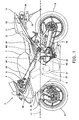
- Fig. 1 is a side view of a motorcycle according to an embodiment of the present invention
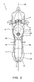
- Fig. 2 is a plan view of the motorcycle of Fig. 1 ;
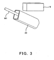
- Fig. 3 is an enlarged perspective view showing a region surrounding a battery mounted in the motorcycle of Fig. 1 ;
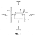
- Fig. 4 is a plan view showing a relationship between the battery and a multiplex communication line in the motorcycle of Fig. 1 ;
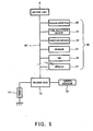
- Fig. 5 is a block diagram showing a communication configuration of the motorcycle of Fig. 1 .
- Fig. 1 is a side view of a motorcycle 1 according to an embodiment of the present invention.
- Fig. 2 is a plan view of the motorcycle 1.
- the motorcycle 1 includes a front fork 4 extending substantially vertically with a predetermined caster angle.
- a front wheel 2, which is a steering wheel, is rotatably mounted to a lower portion of the front fork 4.
- a bar-type steering handle 5 is attached to an upper portion of the front fork 4 by a steering shaft (not shown).
- the steering shaft is rotatably mounted to a head pipe 25 forming a frame of the motorcycle 1.
- the front wheel 2 is steered by the rider's operation of rotating the steering handle 11 to the right or to the left.
- the meter unit 6 includes meters or gauges such as a speed meter that indicates a travel speed of the motorcycle 1, a tachometer that indicates an engine speed of an engine E, a water temperature meter that indicates a temperature of cooling water used to cool the engine E, a neutral indicator lamp, a fuel lamp, and a direction indicator lamp, and has multiplex communication interfaces (not shown) and a control function of the multiplex communication.
- a pair of right and left main frames 26 extend rearward to be tilted slightly downward from the head pipe 25.
- a pair of right and left pivot frames 23 are coupled to rear portions of the main frames 26.
- a swing arm 15 extends substantially forward and rearward and is mounted to each pivot frame member 23 to be vertically pivotable around a front end portion thereof.
- a rear wheel 13, which is a drive wheel, is rotatably mounted to a rear portion of the swing arm 15.
- the engine E is mounted to the main frame 26 and the pivot frame 23 and is positioned between the front wheel 2 and the rear wheel 3, under the main frames 26.
- a generator 8 is mounted on the left side of a crankcase 27 located at a lower portion of the engine E and is coupled to a crankshaft (not shown).
- a cowling 28 is mounted to extend from a front portion of the vehicle body to side portions of the vehicle body so as to cover the engine E, etc.
- a fuel tank 7 is disposed behind the steering handle 5.
- a rider's seat 10 which is straddled by a rider is mounted behind the fuel tank 7.
- a battery 9 is mounted below the fuel tank 7 to be located on a right side region of the vehicle body.
- a tail lamp 14 is attached to a rear end portion of the rear cover 24.
- a regulator 12 is mounted on the right side in a space defined by the rear cover 24 and the rear fender 29 and is configured to regulate a voltage of an electric power supplied from the generator 8 to the battery 9.
- An engine electronic control unit (ECU) 13 which is a rear communication device, is mounted in the space defined by the rear cover 24, the rear fender 29, and the fellow passenger's seat 11 so as to be located under a rear portion of the fellow passenger's seat 11.
- the engine ECU 13 is configured to control a fuel injection amount, an ignition timing, etc, based on information indicating an air intake amount, a throttle opening degree, etc.
- the meter unit 6 is coupled to the engine ECU 13 through a multiplex communication line W1 extending in a longitudinal direction of the vehicle body.
- a multiplex communication line refers to a communication line which allows a number of information to be communicated simultaneously in the form of an electric signal by time multiplexing or by frequency multiplexing.
- the multiplex communication line W1 extends above a center line L1 in a vertical direction of the motorcycle 1 and through a region on the left side of a center line L2 in a lateral (width) direction of the vehicle body along an inner side of the left main frame 26.
- the multiplex communication line W1 is positioned to be at least 100 mm or more distance apart from in-vehicle noise sources that emit an electromagnetic wave noise, for example, the generator 8, the battery 9, and the regulator 12.
- the term “center line L1 in the vertical direction” refers to a horizontal line passing through a 1/2 of a whole height of the vehicle body in a side view
- the term “center line L2 in the lateral direction” refers to a line passing through a center in the lateral direction of the vehicle body in a plan view.
- the generator 8 is disposed under the center line L1 in the vertical direction, whereas the multiplex communication line W1 is disposed above the center line L1.
- the battery 9 is disposed on the right side of the center line L2 in the lateral direction, whereas the multiplex communication line W1 is disposed on the left side of the centre line L2.
- the regulator 12 is disposed on the right side of the center line L2, whereas the multiplex communication line W1 is disposed on the left side of the center line L2.
- Fig. 3 is an enlarged perspective view showing a region surrounding the battery 9 mounted in the motorcycle 1.
- a part of the communication line W1 is inserted into an inner space of the pivot frame 23 having a closed cross-section in the vicinity of the battery 9.
- the pivot frame 23 serves to shield a noise emitted from a region located in close proximity to the battery 9, thus improving communication stability of the multiplex communication line W1.
- a noise shield member comprises a vehicle body frame formed of metal having a closed cross-section in the vicinity of a noise source mounted in the vehicle body.
- the generator 8 is coupled to the regulator 12 through a power wire W2.
- the power wire W2 is guided, through a region under the centre line L1, to a region on the right side of the center line L2, and then to a region above the centre line L1.
- the power wire W2 is guided to extend through the right side region of the vehicle body and is coupled to the regulator 12.
- the regulator 12 is coupled to the battery 9 through a power wire W3 extending through the right side region of the vehicle body on the right side of the center line L2.
- the electric power generated in the generator 8 is sent to the regulator 12 through the power wire W2 and to the battery 9 through the power wire W3 and stored therein.
- Fig. 4 is a plan view showing a relationship between the battery and the multiplex communication line W1.
- the battery 9 is mounted in such a manner that a cathode 9a is positioned rightward relative to an anode 9b in the vehicle body so that the distance between the cathode 9a and the multiplex communication line W1 is larger than the distance between the anode 9b and the multiplex communication line W1.
- the power wire W3 is connected to the cathode 9a of the battery 9 and is guided to the right in the vehicle body so as to be away from the multiplex communication line W1.
- An earth wire W4 is connected to the anode 9b of the battery 9 and is also guided to the right in the vehicle body so as to be away from the multiplex communication line W1.
- Fig. 5 is a block diagram showing a communication configuration of the motorcycle 1.
- a fuel injection device 18, an engine ignition device 19, a keyless entry ECU 20 for controlling a keyless entry system, sensors 21, switches 22, an ECU 31 for an anti-lock braking system (ABS), etc, which are intermediate communication devices (node) 30, are arranged in the longitudinal direction of the vehicle body and are coupled to an intermediate region of the multiplex communication line W1 coupling the meter unit 6 to the engine ECU 13.
- a speed sensor 16 that detects a travel speed of the motorcycle 1
- a water temperature sensor 17 that detects a temperature of the cooling water used to cool the engine E, etc are coupled to the engine ECU 13.
- an in-vehicle local area network is configured by using the multiplex communication line W1, and data communication is carried out by time multiplexing by employing a controller area network (CAN) as a communication protocol.
- the communication protocol is not intended to be limited to the CAN but may be other suitable communication protocol such as FlexRay, TTP, or Lin.
- a network topology of the CAN is a bus topology. All communication devices are coupled onto a bus and are configured to receive data simultaneously, and communication devices other than the associated communication devices are configured to discard the received data. This is called a multicast communication.
- the network topology may be a star topology or a ring topology.
- a carrier sense multiple access/collision detection (CSMA/CD) method is employed as an access method.
- CSMA/CD carrier sense multiple access/collision detection
- a communication device which has a desire to transmit data, checks whether or not there is a communication being performed on the bus, and starts data transmission if there is no communication. If signal collision occurs due to simultaneous transmission from plural communication devices, then a communication device with a lower priority halts data transmission and makes a request for re-transmission after an elapse of a certain time.
- the engine ECU 13 since the engine ECU 13 is positioned at a rear portion of the vehicle body so that the multiplex communication line W1 coupling the meter unit 6 to the engine ECU 13 extends from the front portion of the vehicle body to the rear portion of the vehicle body, the intermediate communication devices 30 such as the fuel injection device 18, the engine ignition device 19, the keyless entry ECU 20, the sensors 21, and the switches 22, are coupled to the multiplex communication line W1 efficiently through short lines.
- the engine ECU 13 by positioning the engine ECU 13 at the rear portion of the vehicle body, an extra space is formed in the vicinity of the rider's seat 10 because of the absence of the engine ECU, and thus other components can be laid out flexibly.
- a communication line does not substantially increase in number if the communication devices increase in number.
- harness wires can be reduced, and system extensibility can be maintained.
- the multiplex communication line W1 is positioned on the opposite side of the in-vehicle noise sources such as the generator 8, the battery 9, and the regulator 12, in the lateral direction or in the vertical direction, it is possible to inhibit entry of a noise into a signal to be transmitted through the multiplex communication line W1.
- a suitable communication environment is formed in the motorcycle 1.
- the battery 9 is mounted in such a manner that the anode 9b which is connected to the ground is disposed in the vicinity of the multiplex communication line W1 and the cathode 9a is disposed distant from the multiplex communication line W1, the noise associated with the battery 9 does not substantially affect the multiplex communication line W1.
- the power line W3 coupled to the cathode 9a of the battery 9 and the earth wire W4 coupled to the anode 9b are guided to the right in the vehicle body so as to be away from the multiplex communication line W1, the noise associated with the power wire W3 and the earth wire W4 does not substantially affect the multiplex communication line W1.
- the engine ECU 13 is disposed as the rear communication device coupled to the rear end of the multiplex communication line W1
- other ECU such as the keyless entry ECU 20 may alternatively be disposed there.
- the multiplex communication line W1 is disposed on the opposite side of the noise sources, it may alternatively be disposed in a position on the same side where it is not subjected to the noise.
- the multiplex communication line W1 is positioned to be 100 mm or more distance apart from the noise source so as not to be subjected to the noise, the distance may be determined according to the intensity of the noise.
Landscapes
- Engineering & Computer Science (AREA)
- Mechanical Engineering (AREA)
- Motorcycle And Bicycle Frame (AREA)
- Cable Transmission Systems, Equalization Of Radio And Reduction Of Echo (AREA)
- Mobile Radio Communication Systems (AREA)
Claims (9)
- Motocycle (1) comprenant :plusieurs dispositifs de communication (6, 13, 30) intégrés dans un corps de véhicule du motocycle (1) ; etune ligne de communication multiplex (W1) grâce à laquelle les dispositifs de communication (6, 13, 30) sont couplés entre eux ; étant précisé que les dispositifs de communication sont conçus pour réaliser une communication de données multiplexée par l'intermédiaire de la ligne de communication multiplex (W1) ;étant précisé qu'une partie de la ligne de communication multiplex (W1) est insérée dans un espace intérieur d'un élément écran acoustique comprenant un cadre, de corps de véhicule (23) en métal à section transversale fermée, près d'une source de bruit (9) montée dans le corps de véhicule.
- Motocycle (1) selon la revendication 1, dans lequel la distance entre la ligne de communication multiplex (W1) et la source de bruit (9) est de 100 mm ou plus.
- Motocycle (1) selon la revendication 2, dans lequel la ligne de communication multiplex (W1) est disposée sur un côté opposé de la source de bruit (9) par rapport à un axe central (L2) dans le sens de la largeur du corps de véhicule, ou sur un côté opposé de la source de bruit par rapport à un axe central dans un sens vertical du corps de véhicule.
- Motocycle (1) selon l'une quelconque des revendications précédentes, dans lequel la source de bruit est une batterie (9) qui est montée de telle sorte qu'une cathode (9a) se trouve plus loin de la ligne de communication multiplex (W1) qu'une anode (9b).
- Motocycle (1) selon la revendication 4, dans lequel des fils électriques (W3, W4) sont reliés respectivement à la cathode (9a) et à l'anode (9b) de la batterie (9) et sont guidés respectivement à partir de la cathode et de l'anode de manière à être éloignés de la ligne de communication multiplex (W1).
- Motocycle (1) selon l'une quelconque des revendications précédentes, dans lequel les dispositifs de communication comprennent un dispositif de communication avant (6) monté sur une partie avant du corps de véhicule, un dispositif de communication carrière (13) monté sur une partie arrière du corps de véhicule, et un dispositif de communication intermédiaire (30) disposé entre le dispositif de communication avant (6) et le dispositif de communication arrière (13) ; et
dans lequel la ligne de communication multiplex (W1) s'étend de la partie avant du corps de véhicule jusqu'à la partie arrière du corps de véhicule, entre le dispositif de communication avant (6) et le dispositif de communication arrière (13). - Motocycle (1) selon la revendication 6, dans lequel le dispositif de communication avant est une unité formant compteur (6), et le dispositif de communication arrière est une unité de commande électronique (13).
- Motocycle (1) selon la revendication 6 ou 7, dans lequel le dispositif de communication carrière (13) est monté dans un espace défini par un garde-boue (29) et un recouvrement arrière (24) montés au-dessus d'une roue arrière (3).
- Motocycle (1) selon l'une quelconque des revendications précédentes, dans lequel le cadre de corps de véhicule (23) est tubulaire.
Applications Claiming Priority (1)
| Application Number | Priority Date | Filing Date | Title |
|---|---|---|---|
| JP2005268739A JP4717569B2 (ja) | 2005-09-15 | 2005-09-15 | 自動二輪車 |
Publications (3)
| Publication Number | Publication Date |
|---|---|
| EP1764295A2 EP1764295A2 (fr) | 2007-03-21 |
| EP1764295A3 EP1764295A3 (fr) | 2009-02-18 |
| EP1764295B1 true EP1764295B1 (fr) | 2010-07-21 |
Family
ID=37533337
Family Applications (1)
| Application Number | Title | Priority Date | Filing Date |
|---|---|---|---|
| EP06254814A Ceased EP1764295B1 (fr) | 2005-09-15 | 2006-09-15 | Motocyclette |
Country Status (4)
| Country | Link |
|---|---|
| US (1) | US7680564B2 (fr) |
| EP (1) | EP1764295B1 (fr) |
| JP (1) | JP4717569B2 (fr) |
| DE (1) | DE602006015575D1 (fr) |
Cited By (1)
| Publication number | Priority date | Publication date | Assignee | Title |
|---|---|---|---|---|
| EP3978292A1 (fr) * | 2020-09-30 | 2022-04-06 | Yamaha Hatsudoki Kabushiki Kaisha | Système d'affichage |
Families Citing this family (19)
| Publication number | Priority date | Publication date | Assignee | Title |
|---|---|---|---|---|
| JP2008114617A (ja) * | 2006-10-31 | 2008-05-22 | Honda Motor Co Ltd | 車両の電装部品配置構造 |
| JP5186325B2 (ja) * | 2008-09-30 | 2013-04-17 | 本田技研工業株式会社 | 車両の通信制御システム |
| JP5359320B2 (ja) * | 2009-01-29 | 2013-12-04 | 株式会社ジェイテクト | 工作機械 |
| JP2010203388A (ja) * | 2009-03-05 | 2010-09-16 | Honda Motor Co Ltd | 電装品の配置構造 |
| JP5300142B2 (ja) * | 2009-08-31 | 2013-09-25 | 本田技研工業株式会社 | 自動二輪車 |
| US8447436B2 (en) | 2010-06-29 | 2013-05-21 | Harley-Davidson Motor Company Group, LLC | Handlebar control system |
| IT1402545B1 (it) | 2010-10-29 | 2013-09-13 | Cefriel Società Consortile A Responsabilità Limitata | Apparecchi, sistema e procedimento per rilevare incidenti |
| IT1402544B1 (it) * | 2010-10-29 | 2013-09-13 | Dainese Spa | Apparecchi, sistema e procedimento per la protezione personale |
| JP5725659B2 (ja) * | 2011-08-29 | 2015-05-27 | 本田技研工業株式会社 | 車両の瞬間燃費表示装置 |
| WO2015083206A1 (fr) * | 2013-12-06 | 2015-06-11 | 川崎重工業株式会社 | Véhicule motorisé à deux roues |
| US10384724B1 (en) * | 2018-07-25 | 2019-08-20 | Honda Motor Co., Ltd. | Cover for regulator |
| JP6908575B2 (ja) * | 2018-12-25 | 2021-07-28 | 本田技研工業株式会社 | 鞍乗型車両 |
| JP6980641B2 (ja) * | 2018-12-25 | 2021-12-15 | 本田技研工業株式会社 | 鞍乗型車両 |
| US11760434B2 (en) * | 2019-01-07 | 2023-09-19 | Polaris Industries Inc. | Recreational vehicles with heated components |
| CN210391424U (zh) * | 2019-05-31 | 2020-04-24 | 赛格威科技有限公司 | 全地形车 |
| ES2955222T3 (es) * | 2019-07-02 | 2023-11-29 | Yamaha Motor Co Ltd | Vehículo montado |
| JP7353493B2 (ja) * | 2020-06-23 | 2023-09-29 | 本田技研工業株式会社 | 鞍乗り型車両 |
| CN219192443U (zh) * | 2020-06-23 | 2023-06-16 | 本田技研工业株式会社 | 跨骑型车辆 |
| WO2021261275A1 (fr) * | 2020-06-23 | 2021-12-30 | 本田技研工業株式会社 | Véhicule du type à selle |
Family Cites Families (20)
| Publication number | Priority date | Publication date | Assignee | Title |
|---|---|---|---|---|
| GB784421A (en) | 1954-02-25 | 1957-10-09 | Victoria Werke Ag | Improvements in or relating to frames for motor scooters |
| US3651454A (en) * | 1969-12-15 | 1972-03-21 | Borg Warner | Automotive multiplex system |
| JPS5820578A (ja) * | 1981-07-29 | 1983-02-07 | 本田技研工業株式会社 | 自動2輪車における電子制御装置 |
| JPS6166436A (ja) * | 1984-09-08 | 1986-04-05 | Yamaha Motor Co Ltd | 自動二輪車用信号処理装置 |
| JPS6171283A (ja) * | 1984-09-15 | 1986-04-12 | ヤマハ発動機株式会社 | 自動二輪車の集中制御装置 |
| JPS6198649A (ja) * | 1984-10-19 | 1986-05-16 | Yamaha Motor Co Ltd | 車両の集中制御装置 |
| FR2726411B1 (fr) * | 1994-10-26 | 1997-01-17 | Peugeot | Systeme de communication d'informations par courants porteurs, notamment pour un vehicule automobile |
| JP3376746B2 (ja) * | 1995-03-07 | 2003-02-10 | スズキ株式会社 | 自動二輪車の車速センサ装置 |
| JPH08298480A (ja) | 1995-04-27 | 1996-11-12 | Honda Motor Co Ltd | 自動車用多重通信システムの配線構造 |
| FI113420B (fi) * | 1997-11-14 | 2004-04-15 | Iws Internat Inc Oy | Älykäs ohjausjärjestelmä kulkuneuvon virranjakelua varten |
| JP3658503B2 (ja) | 1998-07-03 | 2005-06-08 | 株式会社日立製作所 | 乗物の電力供給装置及び集約配線装置 |
| US6249060B1 (en) * | 1999-06-18 | 2001-06-19 | Jonathan P. Osha | Multiplexed cabling system for a vehicle |
| JP4262835B2 (ja) * | 1999-06-24 | 2009-05-13 | パナソニック株式会社 | 電動式自転車 |
| JP2002140800A (ja) * | 2000-11-02 | 2002-05-17 | Yamaha Motor Co Ltd | 自動二輪車の情報提供装置 |
| JP2003046453A (ja) * | 2001-07-31 | 2003-02-14 | Denso Corp | 電源ic |
| JP4464589B2 (ja) * | 2001-08-31 | 2010-05-19 | 本田技研工業株式会社 | 自動2輪車の車体フレーム構造 |
| JP4640904B2 (ja) * | 2001-09-07 | 2011-03-02 | 本田技研工業株式会社 | ステアリングダンパ装置 |
| JP2004241998A (ja) | 2003-02-05 | 2004-08-26 | Yazaki Corp | 車両用電源重畳多重通信装置及び車両用電源重畳多重通信方法 |
| JP4337365B2 (ja) | 2003-02-28 | 2009-09-30 | スズキ株式会社 | 自動二輪車のバッテリー保持構造 |
| JP4401286B2 (ja) | 2004-12-28 | 2010-01-20 | 本田技研工業株式会社 | 電動二輪車のハーネス構造 |
-
2005
- 2005-09-15 JP JP2005268739A patent/JP4717569B2/ja not_active Expired - Fee Related
-
2006
- 2006-09-14 US US11/522,121 patent/US7680564B2/en active Active
- 2006-09-15 EP EP06254814A patent/EP1764295B1/fr not_active Ceased
- 2006-09-15 DE DE602006015575T patent/DE602006015575D1/de active Active
Cited By (1)
| Publication number | Priority date | Publication date | Assignee | Title |
|---|---|---|---|---|
| EP3978292A1 (fr) * | 2020-09-30 | 2022-04-06 | Yamaha Hatsudoki Kabushiki Kaisha | Système d'affichage |
Also Published As
| Publication number | Publication date |
|---|---|
| DE602006015575D1 (de) | 2010-09-02 |
| JP2007076550A (ja) | 2007-03-29 |
| US20070075845A1 (en) | 2007-04-05 |
| EP1764295A3 (fr) | 2009-02-18 |
| EP1764295A2 (fr) | 2007-03-21 |
| US7680564B2 (en) | 2010-03-16 |
| JP4717569B2 (ja) | 2011-07-06 |
Similar Documents
| Publication | Publication Date | Title |
|---|---|---|
| EP1764295B1 (fr) | Motocyclette | |
| EP2447143B1 (fr) | Motocycle | |
| EP2180545B1 (fr) | Véhicule de type à enfourcher | |
| AU2012203540B8 (en) | Electrical unit containing structure for saddle type electric vehicle | |
| JP2019048553A (ja) | 鞍乗型車両 | |
| CN102745288B (zh) | 骑乘型车辆 | |
| JP2009234424A (ja) | 鞍乗り型車両のハーネス保持構造 | |
| JPWO2019186945A1 (ja) | 鞍乗型車両 | |
| WO2020129789A1 (fr) | Véhicule à selle | |
| EP2990313B1 (fr) | Structure de montage d'amplificateur de dispositif d'immobilisation de motocyclette | |
| EP2949562B1 (fr) | Véhicule à moteur | |
| EP2497687B1 (fr) | Véhicule doté d'un carénage | |
| EP3450292B1 (fr) | Motocyclette | |
| EP4244125A1 (fr) | Véhicule de type à enfourcher | |
| EP2949558B1 (fr) | Véhicule du type monté à califourchon | |
| JP6119161B2 (ja) | 自動二輪車 | |
| JP2020179722A (ja) | 鞍乗車両 | |
| JP5667929B2 (ja) | 自動二輪車 | |
| JP3376746B2 (ja) | 自動二輪車の車速センサ装置 | |
| EP2436556B1 (fr) | Structure de câblage de combinaison de feu arrière | |
| TWI841289B (zh) | 跨坐型車輛 | |
| JP5656818B2 (ja) | 鞍乗型車両 | |
| WO2018178835A1 (fr) | Dispositif de charge d'équipement électronique pour un véhicule à deux roues | |
| CN111717313B (zh) | 鞍座型车辆 | |
| WO2022113123A1 (fr) | Véhicule du type à enfourcher |
Legal Events
| Date | Code | Title | Description |
|---|---|---|---|
| PUAI | Public reference made under article 153(3) epc to a published international application that has entered the european phase |
Free format text: ORIGINAL CODE: 0009012 |
|
| AK | Designated contracting states |
Kind code of ref document: A2 Designated state(s): AT BE BG CH CY CZ DE DK EE ES FI FR GB GR HU IE IS IT LI LT LU LV MC NL PL PT RO SE SI SK TR |
|
| AX | Request for extension of the european patent |
Extension state: AL BA HR MK YU |
|
| PUAL | Search report despatched |
Free format text: ORIGINAL CODE: 0009013 |
|
| AK | Designated contracting states |
Kind code of ref document: A3 Designated state(s): AT BE BG CH CY CZ DE DK EE ES FI FR GB GR HU IE IS IT LI LT LU LV MC NL PL PT RO SE SI SK TR |
|
| AX | Request for extension of the european patent |
Extension state: AL BA HR MK RS |
|
| AKX | Designation fees paid |
Designated state(s): DE IT |
|
| RTI1 | Title (correction) |
Free format text: MOTORCYCLE |
|
| GRAC | Information related to communication of intention to grant a patent modified |
Free format text: ORIGINAL CODE: EPIDOSCIGR1 |
|
| GRAP | Despatch of communication of intention to grant a patent |
Free format text: ORIGINAL CODE: EPIDOSNIGR1 |
|
| RIC1 | Information provided on ipc code assigned before grant |
Ipc: B62J 99/00 20090101AFI20091218BHEP |
|
| GRAS | Grant fee paid |
Free format text: ORIGINAL CODE: EPIDOSNIGR3 |
|
| GRAA | (expected) grant |
Free format text: ORIGINAL CODE: 0009210 |
|
| AK | Designated contracting states |
Kind code of ref document: B1 Designated state(s): DE IT |
|
| REF | Corresponds to: |
Ref document number: 602006015575 Country of ref document: DE Date of ref document: 20100902 Kind code of ref document: P |
|
| PLBE | No opposition filed within time limit |
Free format text: ORIGINAL CODE: 0009261 |
|
| STAA | Information on the status of an ep patent application or granted ep patent |
Free format text: STATUS: NO OPPOSITION FILED WITHIN TIME LIMIT |
|
| 26N | No opposition filed |
Effective date: 20110426 |
|
| REG | Reference to a national code |
Ref country code: DE Ref legal event code: R097 Ref document number: 602006015575 Country of ref document: DE Effective date: 20110426 |
|
| PGFP | Annual fee paid to national office [announced via postgrant information from national office to epo] |
Ref country code: IT Payment date: 20150925 Year of fee payment: 10 |
|
| PG25 | Lapsed in a contracting state [announced via postgrant information from national office to epo] |
Ref country code: IT Free format text: LAPSE BECAUSE OF NON-PAYMENT OF DUE FEES Effective date: 20160915 |
|
| REG | Reference to a national code |
Ref country code: DE Ref legal event code: R081 Ref document number: 602006015575 Country of ref document: DE Owner name: KAWASAKI MOTORS, LTD., AKASHI-SHI, JP Free format text: FORMER OWNER: KAWASAKI JUKOGYO K.K., KOBE, HYOGO, JP |
|
| PGFP | Annual fee paid to national office [announced via postgrant information from national office to epo] |
Ref country code: DE Payment date: 20230802 Year of fee payment: 18 |
|
| REG | Reference to a national code |
Ref country code: DE Ref legal event code: R119 Ref document number: 602006015575 Country of ref document: DE |
|
| PG25 | Lapsed in a contracting state [announced via postgrant information from national office to epo] |
Ref country code: DE Free format text: LAPSE BECAUSE OF NON-PAYMENT OF DUE FEES Effective date: 20250401 |